Visualization of Component-based Software
Jean-Marie Favre
Humberto Cervantes
Adele Team, Laboratoire LSR-IMAG
University of Grenoble, France
http://www-adele.imag.fr/(GSEE|BEANOME)Abstract
New component-based techniques are emerging, leading to new ways to develop software. Industrial component technologies such as COM, JavaBeans, EJB, or CCM are powerful but their extensive use leads to component-based software products that are difficult to understand. This paper discusses several issues in visualizing component-based software products, namely the visualization of the component model itself, the visualization of software components and finally the visualization of software assemblies.
1. Introduction
It is generally accepted that the construction of software could be realized by means of assembling “building blocks” that could be reused to create different types of applications. However this idea had not been put into practice at a large scale until the proposals, in the recent years, of industrial-strength component technologies such as Microsoft's DOM/ DCOM [33][34] and .NET [35], Sun's JavaBeans [28] and Enterprise Java Beans (EJB) [19], OMG's Corba Component Model (CCM) [23], Dassault Systèmes’ Object Modeler (OM) [18], and OSGi [26] among others. According to a market assessment of component based software engineering realized by the Software Engineering Institute, component technology is “emerging as a major factor in how systems are being, and will be, built for the foreseeable future” [31].
The impact that component technologies are expected to have on software development may have repercussions on software visualization (SV). It is important to notice though that Component Based technology can be considered by the SV research community from two different points of view.
• Firstly, CB technologies can be considered as a source of new issues, since it is necessary to deal with concepts that have potentially not been treated before. • Secondly, CB technologies can be considered as a source of new solutions, in particular concerning the construction of SV tools.
This duality can be compared with the impact that the object-oriented (OO) paradigm had on software visualization. A lot of work has been dedicated both to the visualization of OO software and to the development of OO frameworks to build visualization tools.
This paper focuses on the first point, and more precisely its goal is to answer the question “how software visualisation could support component-based development?”
The paper is structured as follows: Section 2 describes the motivation of our work from an industrial experience with the Dassault Systemes company. Section 3 briefly introduces the features of industrial component technologies. Then section 4 describes the related issues from a software understanding perspective. Section 5 explains how SV could help in understanding CB software products. And finally, section 5 presents the conclusions.
2. Background
The motivation of using SV to understand CB software products originated partly from a collaboration between the LSR laboratory and the Dassault Systèmes (DS) company. DS is the world leader in CAD/CAM and one the major software companies in Europe. DS is also one of the pioneers in component-based technology. In the mid 90's this company started to develop a proprietary component technology. Since then DS has developed more than 8000 components. The development and evolution of such huge software naturally raises various issues. In particular this experience revealed a strong need to support the understanding of large component-based software [18]. As a result of this work, a visualization tool, the OMVT, was developed to display graphically DS’ components [15][12]. While our initial research in CB development focused on specific component technologies such as DS’s OM and Sun’s JavaBeans, we further studied all major component technologies found in industry, to be able to obtain a global view on this emerging paradigm [16]. Currently our research work is at the intersection of reverse engineering and component-based software development.
3. Component-based technologies
There are many definitions in the literature of what is (and what is not) a component. For example, Szyperski
defines components as following :
"Components are units of composition with contractually specified interfaces and explicit context dependencies only. Components can be deployed independently and are subject to composition by third parties" [39].
Unfortunately, there is no real consensus about the exact definition of components. One important aspect of the component-based approach is that, at different moments of the software lifecycle, people with different skills should be able to handle components in different ways. While a component developer requires programming knowledge to implement the component, an assembler must be able to build a component-based application without any knowledge of such kind, for example by just connecting available components visually. Similarly, the administrator of a site should be able to deploy a component-based application on a server by just configuring some properties of the application and maybe by connecting some parts of the application to some components already installed on the server. Later, it should be possible to replace a component by another one without having to modify the code of the application.
The lack of consensus about an exact definition of components might take its root in the diversity of their requirements and also in the fact that this field is essentially driven by the emergence and continual evolution of industrial component-based technologies. This includes for instance models like COM, EJB, JavaBeans, CCM, OSGI and .NET. Though each technology shares with the others the notion of "component", they all focus on quite different issues depending on their target application domain.
For instance the Corba Component Model (CCM) and Enterprise Java Beans (EJB) focus on the construction of distributed server applications that are often web oriented. These technologies provide features to allow the addition of non functional properties to a component without the need of changing the code of the component itself. These so-called non functional properties include for instance support for persistence, distribution and transaction management. Component technologies such as CCM or EJB make it possible for example to configure, without making changes in the code of an application, whether two components will execute on different machines or not.
This contrasts with the focus of Microsoft’s COM and Dassault Systèmes’ OM which bring solutions to build components from a set of independently developed pieces
of code. Typically different C++ classes produced by different companies can be gathered together and appear as a whole to an application; all of this in a transparent fashion and without having to change the code of the application.
In a different domain, OSGI considers components as units of deployment and provides a framework that allows to install and update components without having to stop the execution of a running application (this is also known as hot swapping). The ability to administrate an application remotely is an important feature of OSGI since the application domain includes target products such as set-top boxes, routers and consumer electronics.
Finally, to illustrate the diversity of the current component technologies, let us consider the JavaBeans technology. The specification of this component model starts with the following statement:
"The goal of the Java Beans APIs is to define a software component model for Java, so that third party ISVs can create and ship Java components that can be composed together into applications by end users" ... "A Java Bean is a reusable software component that can be manipulated visually in a builder tool" [21].
Visual assembly and customization of components thus play an essential role in the JavaBeans component model.
4. Issues related with component technologies
The use of industrial component technologies raises various issues. A major difficulty is that they focus on practical problems and technical solutions rather than on concepts. These technologies are often described in technical terms through many implementation details. While the desired goal is that of simplifying programming of component-based applications, the focus on technical details often results in difficulties to understand the concepts and principles.In practice, industrial component technologies are all built as a layer on top of some other existing technology, typically an object-oriented programming language. While new concepts are introduced, no specific language is provided to express these concepts1. For instance JavaBeans, EJB and OSGI are based on the Java programming language, COM and OM are mainly based on C++, CCM is based on Corba 2, etc.
This means that in practice conceptual entities must be implemented "by hand" in a conventional programming language, using for example (1) naming conventions,
1. CCM is an exception to this rule since it defines various languages to describe for example the interface of a component.
(2) established programming patterns, and/or (3) specific APIs. In practice a component-based software is far more simple to understand when considered at the conceptual level than at the implementation level. Especially when there is no direct mapping between those levels.
To illustrate these aspects let us consider for instance the JavaBeans component technology. From a conceptual point of view, a set of "properties" can be attached to a given "component". From an implementation point of view a simple property will be represented by a pair of methods: take for example a method getA and setA for a property named A. Actually, using this naming convention is not compulsory: Java Beans APIs provides features to make explicit the mapping between each property and Java methods.
While the implementation of simple concepts is straightforward other concepts require much more attention. For instance Java Beans introduce the concept of "constrainted properties", meaning that a change of such a property is constrained to the validation by some other components: the change will actually occur only if no components emit a veto to that change. While the concept is relatively simple to understand, the implementation of this concept is done through a large set of programming entities and a combination of various design patterns. In practice the description of this single conceptual entity will be spread over various files in the source code.
The example described above just illustrates some of the features of Java Beans technology. One major problem is that each component technology defines its own set of concepts. This may include for example the concept of "component", "interface", "implementation", "event source", "event sink", and so on. For each component technology, there should be an underlying component model, that is a well-formed set of concepts and rules that explain how concepts can be composed to build valid artefacts.
For instance, a component model would state that a component "implements" many "interfaces", that it "provides" different "event sources", etc. Unfortunately with current component technologies, there is no clear distinction between concepts and their implementations. There is no explicit description of the underlying component model.
In this context, learning is often achieved through the reading of specification documents that are often obscure or through huge books that give programmers a long list of recipes to implement and connect components. For instance the first specification of JavaBeans [21] is a document of 114 pages with some "advanced features" poorly documented. The CCM description is made of 1172 pages of technical specifications.
Once implemented, components and component-based applications can become difficult to understand. A simple
concept may be implemented by means of many artefacts spread in the source code and other configuration files expressed in many different formats.
Moreover, often there are many choices of implementation to implement a given concept. Each implementation can be useful since they provide different properties in terms of performance or extensibility for example.
Finally, sometimes programmers have to write code interacting with generated code they don't really understand. This is the case for instance when using technology such as EJB or CCM which are quite difficult to understand. This can turn the development and evolution of complex component-based software into a really challenging task.
Summing up, the emergence of component-based technologies is full of promises. There are however at least two major problems:
• it is very difficult in practice to get a clear vision of a given component model and
• it is difficult to get a clear vision of the structure of a component-based software.
As pointed out before, these problems are due to the fact that component-based technologies define a set of new concepts but no corresponding language or model. As a result software engineers think in terms of low level programming entities rather that in terms of conceptual entities.
5. Visualization of Component-based Software
One way to improve the understanding of software is to use software visualization techniques. This section discusses several issues in visualizing component-based software products. The first issue is related to the visualization of the component model itself. Then the visualization of software components and software assemblies is considered. Finally the problem of linking concepts with the actual implementation is discussed.5.1. Visualization of the component model
Visualizing software components at a conceptual level is only possible if this level has been previously defined in some way. However, as pointed out before the component model is often implicit, and there is not always a clear distinction between implementation details and concepts.
The first step to solve this problem is to make this component model explicit. This is required to visualize useful abstractions. Our experience in the context of the collaboration with Dassault Systemes suggests that this task can be very hard in practice : it tooks many months to define the component model associated with the OM component
technology. A portion of the resulting component model is described in [15].
One possible manner of visualizing a component model, is by describing it as a set of UML class diagrams. This can be a very effective technique: such diagrams convey much information in a very concise way. The specification of CCM is based on this approach [29]. Note that this kind of models are often referred as meta-models in the object-oriented community. This is the case among other in the context of the UML notation.
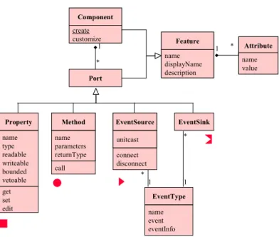
To illustrate this first level of visualization let us consider the portion of the JavaBeans component model as depicted in Figure 1. In this class diagram each box represents a class, that is in this case an important concept of the JavaBeans component model; each link represents a relationship between these concepts. The interesting point here is that this UML class diagram introduces all necessary concepts to describe Java Beans components at a conceptual level without giving any information about implementation details.
This model was elaborated from the careful study of the specification (more than hundred pages of technical descriptions). It summarizes important conceptual information. For example, the diagrams clearly shows that a Bean component may display different kinds of "ports", such as properties, methods or event sources. It also shows that arbitrary attributes can be attached either to components or to ports.
5.2. Visualization of components
The diagram shown in the previous section could be used to improve the understanding of the component technology itself. It could also be used as a basis to define a suitable graphical notation to visualize individual software components.
To enforce the analogy with electronic chips, a traditional way to display components is to represent them as boxes that can be connected together through their ports. An icon could be associated to each type of port. This mapping is defined on the right of Figure 2. An example of component is displayed on the left using this notation.
At this point it is important to stress that a specific notation must be provided for each component technology since each technology is based on a different set of concepts.
Defining a graphical notation to denote components is useful for several reasons:
• it allows software engineers to communicate at the conceptual level without the burden of speaking in technical terms,
• it gives an intuitive view of what a component is in that particular model and
• it helps to understand the component model itself by providing concrete examples.
The last point could be compared to the role of UML instance diagrams since they ease the understanding of UML class diagrams by giving examples. The use of a graphical notation to improve the understanding of a component model is also illustrated in [27]. This article uses such a kind of notation to make CCM intelligible. This
Component create customize Component create customize Port * 1 Feature name displayName description Feature name displayName description Attribute name value Attribute name value * 1 Property name type readable writeable bounded vetoable get set edit EventSink Method name parameters returnType Method name parameters returnType EventSource unitcast EventSource unitcast EventType call name event eventInfo 1 1 * * connect disconnect
Figure 1. A portion of the JavaBean component model
Property Method Event source Event sink (listener) Bounded property vv Constraint property ro Read-only property Write-only property wo
1 Unicast event source
contrasts with the huge CCM specification which is quite difficult to synthesize.
To illustrate the visualization of software components, let us consider the OM Visualization Tool (OMVT) developed specifically to visualize Dassault Systèmes components [15][12]. This tool provides various views of software components. For instance a component can be viewed from an external point of view (Figure 3.b). This view shows only the information that is required to use the component. Just like Microsoft’s COM, the OM component model is based on a single kind of port: interfaces (represented as small circles in the figure).
The OMVT provides many other views focusing on individual components. For instance Figure 3.a depicts the internal view of the same component. A component is made of a set of elementary pieces of code, called “implementations” (an implementation is realized by a C++ class). One of these implementations is called the base (of the component). Other implementations, called extensions, can be attached later to the base in order to extend the component. A fundamental feature is that new extensions can be added at a later time to change or improve the behaviour of the component, all this without any need to
recompile any piece of code. This allow various persons or companies to integrate their work without the need to change the software application they share.
From a concrete point of view, these images are produced automatically as the result of a reverse engineering process. The information contained in these views is spread over many files and many C++ classes. Some links are actually implemented by different code patterns and are based on many different software entities including some macro definitions, various C++ classes and some declarations in configuration files. This conceptual level is easier to understand than the current implementation; especially since many software engineers typically cooperate to build such a component and since none of them have an overall view of the whole component. Figure 7.b shows an another example of the visualization of a component, but in this case the tool used to display it is Sun’s NetBeans [32], and the component model is JavaBeans. Different icons are used to represent the different ports. Unfortunately there is no standard notation for component and each tool may choose to use its own icon sets.
(b) External view
(a) Internal view
Component Direct Interfaces Base Extensions Component inheritance Inherited interfaces Direct Interfaces
Figure 3. An OM component visualized with the OMVT tool [15][12]
5.3. Visualization of assemblies
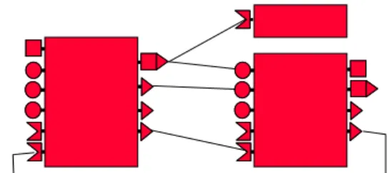
The explicit description of component assemblies is one of the major goals of Architectural Description Languages [25] such as ACME [24] for instance. Visualizing such assemblies is considered as a very important issue since this gives an overall view of an application. Such an assembly could look like the very simple one depicted in Figure 4.
Obviously the types of ports and connections depend on the component model considered.
For instance 5 types of ports can be attached to CCM components: “facets”, “receptacles”, “event source”, “event sinks”, and “properties”. Properties are similar to JavaBeans properties. Facets and receptacles are used to describe provided and required interfaces. They make it possible for two components to communicate in a synchronous way, while event sources and event sinks are used for asynchronous communication.
CCM allows only two kinds of connections: connecting a "facet" to a "receptacle" and connecting an "event source" to an "event sink".
While the concept of assembly is clearly defined in CCM, this is not the case in JavaBeans. This component technology specifies the boundaries of components but does not specify precisely how they can be connected. The responsibility to assemble components is left to the assembly tool. Each tool can provided slightly different ways to connect components. Simple tools, like the BeanBox provided by Sun [28], allow only to establish simple connections between directly pluggable ports. More sophisticated tools make it possible to established more complex connections and generate behind the scene “adaptors” to glue together non compatible ports.
In practice, visualizing assemblies of components is not an easy matter. The first problem is related to the scalability of the visualization technique used. For instance, some complex components may have more than one hundred ports. A potential solution in this case could be to show only connected ports. Another solution is to hide the ports and to show dependencies at a higher level of granularity.
Another issue is the representation of the connections between ports. While binary connections are easily represented by lines (as shown in Figure 4 for example),
more complex connectors are more difficult to visualize, at least in a concise yet precise way.
Finally, a fundamental issue is related to the availability of assembly descriptions. Though one of the goals of most component technologies is to facilitate the assembly of components, component models such as COM, OM and EJB are particularly weak in this respect: such models define a standard way to develop components but the relationships between components are buried deep into the code. In such cases visualizing components assemblies is not a trivial task since this implies extracting data and control flow information from source code and therefore dealing with complex issues such as dynamic binding and polymorphism.
In other component models, such as JavaBeans, there was no standard way (until recently) to describe and store assemblies. This forced different vendors that sell their own (assembly) builders (e.g. Sun’s Netbean, Borland’ s JBuilder, IBM’s VisualAge, Symantec’s VisualCafé) to develop their own formats to save assemblies of components. While some builders generate Java code, other store assemblies in a proprietary format. This is not surprising after all: the primary goal of component models is to define standards for components, not for assemblies, however this lack of standards renders difficult the visualisation of assemblies.
Fortunately exchange formats such as XML are becoming increasingly popular in software industry and some recent component-based technologies enforce the description of assemblies as XML documents. This is the case for instance of CCM and for a new JavaBeans extension for long term persistence.
To investigate the issues related with the visualization of component assemblies and to get a practical experience in this domain we built two different prototypes using the Beanome component model [17]. One important feature of Beanome is that it allows to describe hierachical definitions of components. In other words a component can be recursively defined as assemblies of other components.
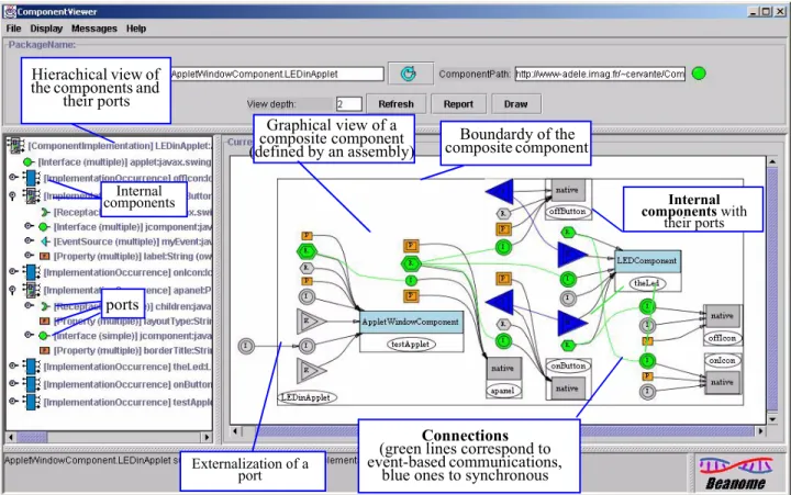
Figure 5 shows an environment that was created to visualize component hierarchies in two different ways, either as a tree or as a graph. The graph view displays components, their ports, and the connections between them. The tree gives a different view of the same information. Our visualization prototype makes it possible to display components at arbitrary nesting levels, although experience shown that visualizing several levels at the same time when there is a significant number of components is not effective. To tune the results, a selection on the depth level of display can be done. At the selected level, components are represented as “black boxes” and the graph does not show the internal structure of these components thus simplifying the overall result.
Figure 6. Visual assembly of a simple composite component using Beanome
Running application resulting from the interactive assembly of component occurrences.
Component palette
Editable view of the assembly. Customization is done by clicking on a property (rectangle). Connections are created by drawing lines between ports. The application is built on the fly.
Boundardy of the composite component Internal components with their ports Connections (green lines correspond to event-based communications,
blue ones to synchronous Hierachical view of
the components and their ports Externalization of a port Graphical view of a composite component (defined by an assembly)
Figure 5. Visualization of a Beanome composite component (defined as an assembly of smaller components) Internal
components
It is interesting to mention that the environment is built out of Beanome components, so it can be used to explore itself. Figure 6 shows a second prototype that was created to explore a different aspect, namely that of visual assembly of components. This prototype allows to connect instances of Beanome components through their ports and to set their properties interactively. While the user is creating the assembly, the result that is being executed is displayed. The resulting assembly can then be stored and later used as the implementation of other components. Although these prototypes are specific to the Beanome component model, the experiences obtained could be applied to other component models as well.
5.4. Link with the implementation
Visualizing component-based software at the conceptual level presents a lot of advantages, especially since this level is far simpler than the implementation level. These views
can improve the understanding of a software product even for its own developers. Currently software engineers develop component-based software in a "blind way". Providing them a visualization tool will enable them to visualize software at the conceptual level. This experience was done in the context of the collaboration with Dassault Systèmes [15]. It showed the importance to make the link between the conceptual view and the implementation level since that level is the one used daily by software developers who think in terms of classes, methods, attributes, configuration files and so on.
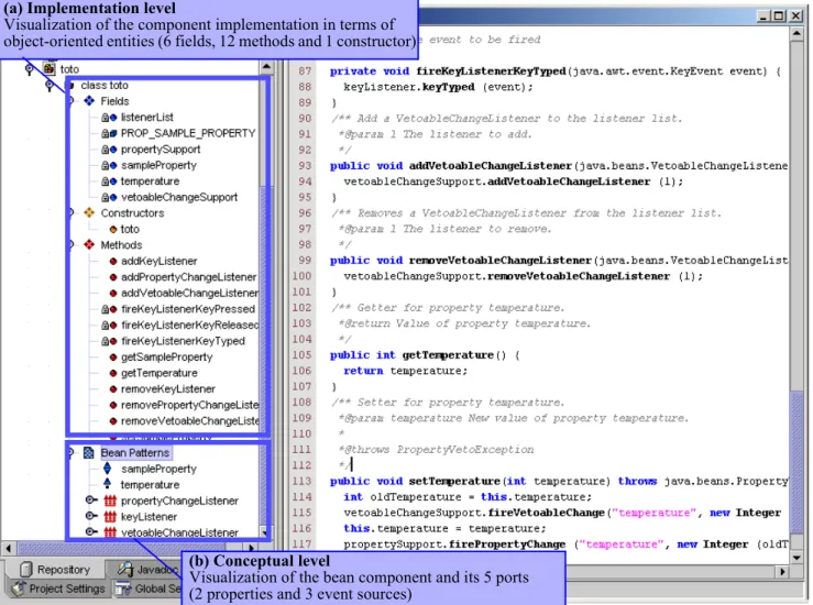
To illustrate this concept, let us consider how the Netbean development environment enforces the link between JavaBeans concepts and their implementations in the Java programming language. A simple JavaBean component is visualized in Figure 7 both at the conceptual level (Figure 7.b) and at the implementation level (Figure 7.a). The actual file is made from more than one hundred lines of code. It is therefore more complex to understand the
(b) Conceptual level
Visualization of the bean component and its 5 ports (2 properties and 3 event sources)
Figure 7. Visualization of JavaBean component with the Netbean integrated development environment.
(a) Implementation level
Visualization of the component implementation in terms of object-oriented entities (6 fields, 12 methods and 1 constructor)
full implementation than the concepts. In the example the code is entirely generated by NetBean, but a developer still needs to know the code if he or she wants to complete it. In this case, the component is represented as a single class and a single file. But this is not always the case. A more sophisticated JavaBean would also include a few other classes for customization purposes.
5.5. Alternatives views
Visualizing the static structure of software components and software assemblies as presented above is a basic requirement in CB tools. This is a first step towards the integration of software visualization and component-based development. However, many alternatives views are also required. For instance, when browsing a huge amount of software entities, metric-based visualizations are necessary [2]. We built such views in the context of the Dassault Systèmes collaboration. Similarly there is a strong need to visualize the result of dynamic analysis of component-based software. In fact all of the techniques proposed to visualize object-oriented software should be adapted to the context of component-based software development.
6. Conclusion
Industrial component technologies are useful, but they are also complex to understand. While new concepts are introduced, usually no specific language is provided to express these concepts. Software engineers have therefore to deal with the implementations of these concepts. In practice the extensive use of component technologies could lead to software products that are difficult to understand. Software visualization could improve the understanding of component-based software products, especially since those software products are frequently developed in a “blind” way, which means that developers work at an implementation level, not at he conceptual level. However, SV for CB technologies is in its beginnings. Some major difficulties are expected in the near future to understand and maintain large industrial component-based software products. This raises a lot of research issues for the SV research community.
Another aspect, that has not been addressed in this paper due to a lack of space, is that component-based software visualisation could benefit from the advances in component-based software development. While current software visualisation tools are developed from scratch or are based on object-oriented frameworks, there is a strong need to integrate such tools or to reuse existing software
visualization components. Currently we are working on testing this approach by developing GSEE, a Generic Software Exploration Environment [13]. GSEE is built out of a well organized set of components that can be used to build software visualisation tools. The component model underlying GSEE, called Beanome [17], is an extension to JavaBeans and uses OSGi [26] as the mechanism to deploy and manage the components.
7. References
[1] I. Crnkovic, M. Larsson, editors; “Building Reliable Component-Based Systems", Archtech House publisher, 2002
[2] S. Demeyer, S. Ducasse, M. Lanza. "An Hybrid Reverse Engineering Approach Combining Metrics and Program Visualisation", Proc. of the Working Conference on Reverse Engineering (WCRE'99), IEEE, 1999.
[3] S.G. Eick, J.L. Steffen, E.E. Sumner, "Seesoft - A Tool For Visualizing Line Oriented Software Statistics", in IEEE Trans. on Software Engineering, Vol. 18, N. 11, Nov. 1992. [4] S. Bassil, R.K. Keller, “Software Visualization Tools: Survey
and Analysis”, Proc. of the 9th International Workshop on Program Comprehension (IWPC’01), IEEE, May 2001. [5] Imagix, http://www.imagix.com
[6] J. Michaud, M.A. Storey, H. Muller, “Integrating Information Sources for Visualizing Java Programs”, International Conference on Software Maintenance (ICSM’01), 2001 [7] Graphviz, http://www.graphviz.org/
[8] J.M. Favre, "Understanding-In-The-Large", Proc. of the 5th International Workshop on Program Comprehension (IWPC'97), IEEE, May 1997.
[9] C. Knight, M. Munro, “Mediating Diverse Visualisations for Comprehension”, Proc. of the 9th International Workshop on Program Comprehension (IWPC’01), IEEE, May 2001. [10] Graphviz, http://www.graphviz.org/
[11] Imagix, http://www.imagix.com
[12] R. Sanlaville, J.M. Favre, Y. Ledru, "Helping Various Stakeholders to Understand a Very Large Software Product" European Conference on Component-Based Software Engineering, 2001
[13] J.M. Favre, "GSEE: a Generic Software Exploration Environment" 9th International Workshop on Program Comprehension (IWPC'2001), May 2001.
[14] J.M.Favre, "A New Approach to Software Exploration: Back-packing with GSEE", European Conference on Software Maintenance and Reengineering (CSMR'2002), March 2002
[15] J.M. Favre, F. Duclos, J. Estublier, R. Sanlaville, J.J. Auffret, "Reverse Engineering a Large Component-based Software Product", Proc. of European Conf. on Software Maintenance and Reengineering, CSMR'2001.
[16] J. Estublier, J.M. Favre; "Component Models and Component Technology", Book chapter in [1]
[17] H. Cervantes, J.M.Favre, F. Duclos; "DescribingHierarchical Compositions of Java Beans with the Beanome Language",
Workshop on Software Composition (SC'2002), ETAPS, Grenoble, 2002
[18] J. Estublier, J.M.Favre, R. Sanlaville, "An Industrial Experience with Dassault Systèmes' Component Model", book chapter in [1]
[19] Sun, http://java.sun.com
[20] H.A. Muller et al, RIGI, http://www.rigi.csc.uvic.ca/ [21] Sun Microsystem. Java Beans 1.01 Specification, 1997 ,
http://java.sun.com/beans
[22] D. Box; "Essential COM", ISBN 0201634465, Addison-Wesley, Jan. 1998
[23] OMG, CORBA Components: Joint Revised Submission. Object Management Group, August 1999
[24] Garlan, D., Monroe, R.T., Wile, D., "Acme: Architectural Description of Component-Based Systems", in Foundations of Component-based systems, Leavens, G.T., Sitaraman, M., Editors, Cambridge University Press, 2000.
[25] Medvidovic, N., Taylor, R.N., A Classification and Comparison Framework for Software Architecture Description Languages. IEEE Transaction on Software Engineering, Vol. 26, No. 1, January 2000.
[26] OSGI Service Gateway Specification, Release 1.0, May 2000. http://www.OSGI.org
[27] Marvie, R., Merle, P., CORBA Component Model: Discussion and Use with OpenCCM, Submitted to a Special Issue of the Informatica - An International Journal of Computing and Informatics Dedicated to "Component Based Software Development", http://corbaweb.lifl.fr/OpenCCM/ [28] Sun Microsystem. Java Beans 1.01 Specification, 1997 ,
http://java.sun.com/beans
[29] OMG, CORBA Components: Joint Revised Submission. Object Management Group, August 1999.
[30] L. Bass et al, “Volume I: Market Assessment of Component-Based Software Engineering”, Technical Note, CMU/SEI-2001-TN-007, Carnegie Mellon University, May 2000. [31] Bachman, F. et al, Volume II: Technical Concepts of
Component-Based Software Engineering” Technical Report CMU/SEI-2000-TR-008, Carnegie Mellon University, May 2000.
[32] NetBeans, an open source, modular IDE. http:// www.netbeans.org
[33] Eddon, G., Eddon, H., Inside COM+ base services, Microsoft Press, 2000.
[34] Eddon, G., Eddon, H., Inside Distributed COM, Microsoft Press, 2000.
[35] Microsoft Development Network (MSDN), July 2001 [36] G. Alder, “Design and Implementation of the JGraph Swing
Component”, http://www.jgraph.com [37] http://www.jhotdraw.org/
[38] http://java.sun.com/products/jfc/tsc/index.html
[39] C. Szyperski, "Component Software and the Way Ahead", Chapter in [40]
[40] G.L. Leavens, M. Sitaraman, “Foundations of Component-Based Systems”, Cambridge University Press, ISBN 0521-77164-1, 2000
![Figure 7.b shows an another example of the visualization of a component, but in this case the tool used to display it is Sun’s NetBeans [32], and the component model is JavaBeans](https://thumb-us.123doks.com/thumbv2/123dok_us/1383764.2685373/5.918.65.845.65.498/figure-example-visualization-component-display-netbeans-component-javabeans.webp)