University of Windsor University of Windsor
Scholarship at UWindsor
Scholarship at UWindsor
Electronic Theses and Dissertations Theses, Dissertations, and Major Papers
8-30-2018
Implementation and Analysis of Direct Torque Control for
Implementation and Analysis of Direct Torque Control for
Permanent Magnet Synchronous Motor Using Gallium Nitride
Permanent Magnet Synchronous Motor Using Gallium Nitride
based Inverter
based Inverter
Junxi Cai
University of Windsor
Follow this and additional works at: https://scholar.uwindsor.ca/etd
Recommended Citation Recommended Citation
Cai, Junxi, "Implementation and Analysis of Direct Torque Control for Permanent Magnet Synchronous Motor Using Gallium Nitride based Inverter" (2018). Electronic Theses and Dissertations. 7502.
https://scholar.uwindsor.ca/etd/7502
This online database contains the full-text of PhD dissertations and Masters’ theses of University of Windsor students from 1954 forward. These documents are made available for personal study and research purposes only, in accordance with the Canadian Copyright Act and the Creative Commons license—CC BY-NC-ND (Attribution, Non-Commercial, No Derivative Works). Under this license, works must always be attributed to the copyright holder (original author), cannot be used for any commercial purposes, and may not be altered. Any other use would require the permission of the copyright holder. Students may inquire about withdrawing their dissertation and/or thesis from this database. For additional inquiries, please contact the repository administrator via email
Implementation and Analysis of Direct Torque Control for Permanent Magnet
Synchronous Motor Using Gallium Nitride based Inverter
By
Junxi Cai
A Thesis
Submitted to the Faculty of Graduate Studies
through the Department of Electrical and Computer Engineering
in Partial Fulfillment of the Requirements for
the Degree of Master of Applied Science
at the University of Windsor
Windsor, Ontario, Canada
2018
Implementation and Analysis of Direct Torque Control for Permanent Magnet
Synchronous Motor Using Gallium Nitride based Inverter
by
Junxi Cai
APPROVED BY:
______________________________________________
O. Jianu
Department of Mechanical, Automotive & Materials Engineering
______________________________________________
M. Abdelkhalek
Department of Electrical and Computer Engineering
______________________________________________
N. C. Kar, Advisor
Department of Electrical and Computer Engineering
iii
DECLARATION OF ORIGINALITY
I hereby certify that I am the sole author of this thesis and that no part of this
thesis has been published or submitted for publication.
I certify that, to the best of my knowledge, my thesis does not infringe upon
anyone’s copyright nor violate any proprietary rights and that any ideas, techniques,
quotations, or any other material from the work of other people included in my
thesis, published or otherwise, are fully acknowledged in accordance with the
standard referencing practices. Furthermore, to the extent that I have included
copyrighted material that surpasses the bounds of fair dealing within the meaning of
the Canada Copyright Act, I certify that I have obtained a written permission from
the copyright owner(s) to include such material(s) in my thesis and have included
copies of such copyright clearances to my appendix.
I declare that this is a true copy of my thesis, including any final revisions,
as approved by my thesis committee and the Graduate Studies office, and that this
thesis has not been submitted for a higher degree to any other University or
iv
ABSTRACT
Permanent magnet synchronous machines (PMSMs) attract considerable
attention in various industrial applications, such as electric and hybrid electric
vehicles, due to their high efficiency and high-power density. In this thesis, the
mathematical model of PMSM and two popular control strategies, field-oriented
control (FOC) and direct torque control (DTC), are analyzed and compared. The
results demonstrated that the DTC has better dynamic response in comparison to
FOC. Moreover, DTC can eliminate the use of position sensor, which will save the
cost of the PMSM drive system. Therefore, this thesis focuses on the design and
implementation of high-performance DTC for PMSMs with a Gallium Nitride (GaN)
based high switching frequency motor drive.
First, the characteristics and operation principles of a PMSM are introduced.
Then, the mathematical models of a PMSM under different coordinate systems are
investigated. Consequently, a PMSM model is developed based on the
dq
rotating
reference frame and implemented in the MATLAB/Simulink for validation. Two
advanced PMSM control strategies, FOC and DTC, are investigated and compared
in terms of control performance through comprehensive simulation studies and the
results demonstrate that DTC has better dynamic performance.
Conventional DTC contributes to higher torque ripple in the PMSM due to
the limited switching frequency in a conventional semiconductor-based motor drive,
which inevitably deteriorates the drive performance. Therefore, this thesis aims to
reduce the torque ripple in the DTC based PMSM drive by using the new generation
wide bandgap switching devices. More specifically, DTC is improved by using the
optimized space vector pulse width modulation strategy and a higher switching
frequency contributed by the GaN based motor drive.
Finally, the proposed DTC-SVM based PMSM control strategy is
implemented on the digital signal processor (DSP) and evaluated on the laboratory
GaN based PMSM drive. Both the simulation and experimental results show that the
proposed improvement in the DTC can further improve the PMSM drive
v
DEDICATION
vi
ACKNOWLEDGEMENTS
First and foremost, I give my sincere thanks to my advisor Dr. Narayan Kar, for
providing me continuous guidance, support and numerous of resources for my study
and research throughout the past two years in my MASc program. He inspired me
with confidence and always encouraged me strive for the best. Dr. Kar treated me
as a friend and a family member. It has been an honour working with him.
I would also like to express my gratitude and respect towards to my thesis committee
members, Dr. Maher Abdelkhalek and Dr. Ofelia A. Jianu for agreeing to serve on
my committee and, attending my seminars and defense. With their valuable
suggestions and comments, I was able improve the quality of my research and this
thesis.
My sincere thanks also go to Dr. Chunyan Lai, who has guided me in a supervisory
role during my MASc study. She not only gave me constructive suggestions, but
also shared her valuable research experience with me, which helped me solve many
problems from my research and industry projects.
I am thankful to past and current lab colleagues and friends who supported me
immensely during my research and life. Starting from Jiangbo Tian, who has
introduced me into this program and continues cooperating with me for research and
industry projects. My research group leader, Dr. Guodong Feng, his attitude to
research inspires me to be diligent to my current and future work.
vii
TABLE OF CONTENTS
DECLARATION OF ORIGINALITY ... iii
ABSTRACT ... iv
DEDICATION ... v
ACKNOWLEDGEMENTS ... vi
LIST OF TABLES ... ix
LIST OF FIGURES ... x
NOMENCLATURE ... xiv
Chapter 1 Introduction ... 1
1.1 Background and Motivation ... 1
1.2 Introduction of PMSMs ... 2
1.3 Control Theory of PMSMs ... 3
1.3.1 Scalar Control ... 3
1.3.2 Field-Oriented Control ... 4
1.3.3 Direct Torque Control ... 6
1.4 Research Objective and Contributions ... 7
1.5 Outline of the Thesis ... 8
Chapter 2 PMSM Modeling and Control Strategies ... 9
2.1. Mathematical Model of PMSMs ... 9
2.2 Comparison Between FOC and DTC Strategies for PMSMs ... 14
2.3 Literature Review of Existing DTC Techniques ... 14
2.4 Principle of DTC ... 17
Chapter 3 Investigations of FOC and DTC of PMSMs through Simulations... 25
3.1 Motor Parameters for Simulation of FOC and DTC ... 25
3.2 Simulation Model of FOC of PMSM ... 25
viii
3.2.2 PI controller parameter tuning for speed control ... 26
3.2.3 Simulation Diagram for FOC of PMSM ... 27
3.3 Simulation model of DTC of PMSM ... 29
3.4 Simulation Results and Analysis ... 32
Chapter 4 Optimization of Conventional DTC for PMSMs Using GaN-based
Inverter ... 38
4.1 Torque Ripple Analysis based on Conventional DTC... 38
4.2 Introduction of Gallium Nitride (GaN) based inverter ... 44
4.3 Optimization for Hardware Implementation of DTC ... 47
4.3.1 The DTC based on SVPWM (DTC-SVM) ... 48
4.3.2 Space Vector Pulse Width Modulation (SVPWM) ... 50
Chapter 5 Implementation and Experimental Investigations of the Proposed
DTC-SVM ... 53
5.1 The Introduction of DSP TMS320F28335 ... 53
5.2 Implementation of FOC ... 55
5.2.1 Level 1 Incremental Build ... 60
5.2.2 Level 2 Incremental Build ... 61
5.2.3 Level 3 Incremental Build ... 64
5.2.4 Level 4 Incremental Build ... 67
5.3 Implementation of DTC-SVM ... 69
5.3.1 Design of ADC Module for Sampling ... 76
5.3.2 Design of QEP Module for Position Calculation ... 77
5.3.3 Design of Speed Calculation Module ... 78
5.3.4 Optimization of Stator Flux Linkage Estimation ... 80
5.3.5 Optimization Software Design for Accelerating the Calculation... 81
5.4. Experiment Results and Analysis ... 81
Chapter 6 Conclusions and Future Work ... 85
6.1. Conclusions ... 85
6.2. Future Work ... 85
REFERENCES/BIBLIOGRAPHY... 87
VITA AUCTORIS ... 93
ix
LIST OF TABLES
Table 2.1. Summary of the comparison between FOC and DTC ... 14
Table 2.2. Switching table in the conventional DTC ... 24
Table 3.1. Motor Parameters for Simulation of FOC and DTC... 25
Table 3.2. Comparison at variable speed with full load. ... 33
Table 4.1. Drive loss comparison between GaN and CoolMOS at varies frequency
... 46
Table 4.2. Relationship between N and sector number. ... 50
Table 4.3. Conducting time
T
1,T
2 in different sectors... 50Table 4.4. Calculation of switch point ... 51
x
LIST OF FIGURES
Figure 1.1. Suppliers of vehicle traction motors. ... 1
Figure 1.2. Different rotor configurations for PMSMs. (a) Surface magnets type (b)
Interior magnets type. ... 3
Figure 1.3. Overview of key competing VFD control platforms. ... 3
Figure 1.4. Block diagram of scalar control for PMSM. ... 4
Figure 1.5. Block diagram of field-oriented control for PMSM. ... 5
Figure 1.6. Block diagram of conventional direct torque control for PMSM. ... 6
Figure 2.1. The stator and rotor flux linkage in different reference frames. ... 10
Figure 2.2. Illustration of the stator flux components in αβ stationary and
synchronously rotating
dq
reference frames. ... 13
Figure 2.3 The relationship between torque and load angle δ of surface PMSMs. 18
Figure 2.4. The relationship between torque and load angle δ of interior PMSMs.
... 19
Figure 2.5. A voltage source inverter-fed PMSM drive system. ... 20
Figure 2.6. Voltage space vectors and sectors in the αβ reference frame. ... 21
Figure 2.7. Illustration of the voltage space vectors effect on the torque and stator
flux. ... 22
Figure 2.8. The control of stator flux linkage and torque. ... 23
Figure 3.2. Diagram of SVPWM block. ... 27
Figure 3.1. Simulation model of FOC of PMSM,
I
d=0 control. ... 28
Figure 3.4. α- and β-axis stator flux linkages calculation block. ... 29
Figure 3.3. Diagram of conventional DTC of PMSM. ... 30
Figure 3.5. Switching table calculation block. ... 31
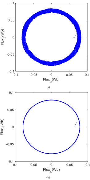
Figure 3.6. Actual stator flux trajectory for DTC of PMSM. ... 31
xi
Figure 3.8. The torque response comparison of FOC and DTC with variable speed
reference. ... 33
Figure 3.9. Speed response comparison of FOC and DTC at 500 rpm. ... 34
Figure 3.10. Torque response comparison of FOC and DTC at 500 rpm. ... 35
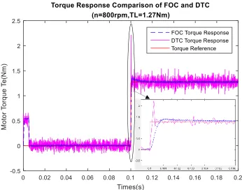
Figure 3.11. Speed response comparison of FOC and DTC at 800 rpm. ... 35
Figure 3.12. Torque response comparison of FOC and DTC at 800 rpm. ... 36
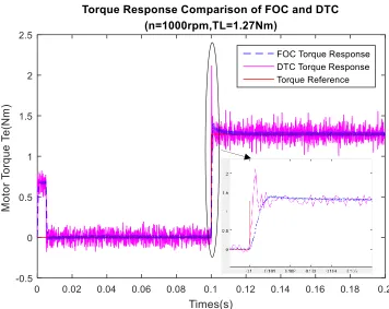
Figure 3.13. Speed response comparison of FOC and DTC at 1000 rpm. ... 36
Figure 3.14. Torque response comparison of FOC and DTC at 1000 rpm. ... 37
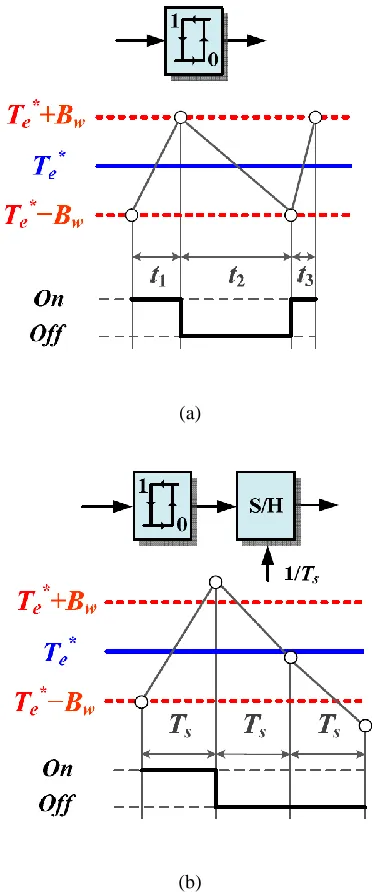
Figure 4.1. Comparison of the switching modes of the hysteresis torque controller
in (a) an analog DTC system and (b) a discrete-time DTC system and the resulting
torque ripples. ... 39
Figure 4.2 Trajectories of the stator flux vector in the stationary reference frame:
(a)
T
s=10
us
; (b)
T
s=1
us
. ... 41
Figure 4.3. Waveforms of the electromagnetic torque: (a)
T
s=10
us
; (b)
T
s=1
us
. ... 42
Figure 4.4. Switching frequency comparison: (a)
T
s=10
us
; (b)
T
s=1
us
. ... 43
Figure 4.5. Comparison of Si, SiC, and GaN for power semiconductor
applications. ... 44
Figure 4.6. Introduction of switching loss. ... 45
Figure 4.7. The comparison between GaN and SiC for switching time. ... 45
Figure 4.8. Drive loss comparison between GaN, CoolMOS and IGBT at varies
frequency... 46
Figure 4.9. Full bridge power loss comparison between COOLMOS, IGBT, SiC
and GaN. ... 47
Figure 4.10. The
α
- and
β
-axis flux vector for DTC-SVM. ... 48
Figure 4.11. The control diagram of DTC-SVM. ... 49
Figure 4.12. Torque Response comparison of conventional DTC and DTC-SVM.
... 52
Figure 5.1. DSP TMS320F28335 Experimental kit... 54
xii
Figure 5.3. Main function flowchart of software design for hardware
implementation of FOC. ... 56
Figure 5.4. ADC interrupt flowchart of software design for hardware
implementation of FOC. ... 57
Figure 5.5. Timer0 interrupt flowchart of software design for hardware
implementation of FOC. ... 58
Figure 5.6. Level1- Incremental system build block diagram. ... 61
Figure 5.7. Output of SVGEN, Ta, Tb, Tc and Tb-Tc waveforms. ... 61
Figure 5.8. Level2- Incremental system build block diagram. ... 62
Figure 5.9. The waveforms of SVGEN_dq1.Ta, rg1.Out, and phase A&B currents.
... 63
Figure 5.10. Level3- Incremental system build block diagram. ... 65
Figure 5.11. Measured theta, rg1.out and Phase A & B current waveforms. ... 66
Figure 5.12. Level4- Incremental system build block diagram. ... 68
Figure 5.13. Measured theta, SVGEN duty cycle, and Phase A&B current
waveforms. ... 69
Figure5.14. Overall block diagram of DTC-SVM. ... 71
Figure 5.15. Main function flowchart of software design for hardware
implementation of DTC-SVM. ... 72
Figure 5.16. The flowchart of ADC interrupt. ... 73
Figure 5.17. The flowchart of Timer0 interrupt. ... 74
Figure 5.18. The flowchart of Timer1 interrupt. ... 76
Figure 5.19. Experiment
α
- and
β
-axis stator phase voltages using DTC-SVM at
900 RPM. ... 82
Figure 5.20. Experiment
α
- and
β
-axis stator phase currents using DTC-SVM at
900 RPM. ... 82
Figure 5.21. Experiment
α
- and
β
-axis stator flux linkages using DTC-SVM at 900
RPM. ... 83
xiii
xiv
NOMENCLATURE
usd, usq : d- and q- axis stator voltages (V)
isd, isq : d- and q- axis stator currents (A)
ψsd, ψsq : d- and q- axis stator flux linkages (V·s)
Ld, Lq : d- and q-axis inductances (H)
usα, usβ : α- and β- axis stator voltages (V)
isα, isβ : α- and β- axis stator currents (A)
ψsα, ψsβ : α- and β- axis stator flux linkages (V·s)
δ : Load angle (rad)
ψs : Stator flux linkage (V·s)
ψf : Rotor flux linkage (V·s)
p : Number of pole pairs
Te : Electromagnetic torque (Nm)
1
Chapter 1
Introduction
1.1 Background and Motivation
Motor control systems play an important role in the development of modern industry and society. The applications range widely from general purpose variable-speed drives, such as water pumps, wind fans and conveyors, to high-performance drives, e.g., robotics, CNC machines and electric vehicles. In the last century, for a long time, direct-current (DC) motor drives dominated the adjustable-speed drive market because of their excellent control performance, e.g., fast torque and speed dynamic response, and precise torque control in four-quadrant operations. There are two key control variables for the DC machine the excitation flux and electromagnetic torque which are naturally orthogonally decoupled so that they can be easily controlled by regulating the field and armature currents, respectively [1]. During DC motor drives dominated the market, the advanced control theory of alternating-current (AC) machines has not been developed and there are limitations in using the semiconductor devices for variable speed drives. As the result, the market for AC motor control systems was limited to undemanding applications, although AC machines have the advantages of simple structure, reliable operation, and easy maintenance. However, in recent years, the development of power electronics technology, microelectronics, and modern control theory has created favorable conditions for the development of AC motor drives. This makes AC motor drives more competitive in terms of performance and economy when compared with DC motor drives [2]. Due to their wide range of uses, there are many different types of AC motor drives.
Fig. 1.1. Suppliers of vehicle traction motors [4].
2
propulsion. Their key features, namely high-power density and high efficiency are attributed to the use of high-energy PM material. PMSMs are becoming dominant in the market share of EV motor drives. [3]. It is reported that 83% of the vehicle traction motor manufacturers supply PMSMs [4], as shown in Fig. 1.1. Only 11% of the manufacturers supply induction machines (IMs) and 6% produce both PMSMs and IMs. Due to their popularity, more and more researchers have focused on the design and development of advanced control methodologies for PMSM drives, which significantly improves the dynamic performance, system robustness and reduce the complexity of control systems for PMSM drives.
1.2 Introduction of PMSMs
In general, PMSMs can be divided into two types according to the shape of back electromotive force (EMF): one with approximately sinusoidal back EMF, which normally adopts the distributed windings. The other with square or trapezoidal back EMF, is normally called brushless DC motor (BLDCM), which adopts the concentrated windings.
The one with sinusoidal back EMF can be broadly divided into non-salient-pole PMSMs (surface-mounted PMSMs) and salient-pole PMSMs (interior PMSMs), based on PM placement and rotor construction. As Fig. 1.2 shows, surface-mounted PMSMs have the PMs mounted on the surface of the rotor core. Consequently, the manufacturing and assembly of this type of machine is relatively simple [5]. On the other hand, interior PMSMs have the PMs buried deeply inside the rotor so that the rotor iron can effectively protect the PMs against centrifugal forces. Such rotor construction is more suitable for high-speed, flux-weakening operations [6].
3
Fig. 1.2. Different rotor configurations for PMSMs. (a) Surface magnets type (b) Interior magnets type [6].
1.3 Control Theory of PMSMs
PMSMs are able to run at different speeds driven by a variable frequency drive. Typically, the classic control theory of PMSMs can be divided into three categories: scalar control, field-oriented control (FOC), and direct torque control (DTC). Each control theory is introduced in the following three sub-sections, respectively.
VFD
Scalar Control
Vector Control
v/f FOC DTC
Fig. 1.3. Overview of key competing VFD control platforms.
1.3.1 Scalar Control
4
Fig. 1.4. Block diagram of scalar control for PMSM.
1.3.2 Field-Oriented Control
Operation theory of the DC motor shows that the produced torque and the flux can be independently tuned. However, AC machines do not have the same features as the DC motor. This becomes a barrier to AC drives to be widely accepted in the market. The issue was not solved until the 1970s when the FOC technique was first proposed for induction machines. Studies of AC machines showed that the mechanisms of torque production in AC and DC machines are quite similar [9]. With the help of the Park transformation, the current components corresponding to the field-magnetizing flux and torque generation in AC machines can be decoupled orthogonally so that the field-magnetizing flux can be controlled without affecting the dynamic response of the torque and vice versa. This is the basic principle of the FOC [10]. In FOC, the flux and torque of AC machines can be separately controlled as DC motors.
5
Fig. 1.5. Block diagram of field-oriented control for PMSM.
The control of the motor is essentially the control of the motor output torque, while the PMSMs FOC achieves indirect control of the torque by controlling the orthogonal current. According to the different control objectives, the specific control method of the stator orthogonal axis current can be divided into the following categories:
(1) Id=0 control: this method is to control the direct axis current to be zero, so there is no direct
axis armature reaction. Regardless of the surface PMSM or interior PMSM, the torque is only proportional to the quadrature axis current, and the control structure is simple. The disadvantage is that the motor power factor decreases as the load increases, and the inverter's capacity requirements are higher.
(2) Maximum torque per ampere (MTPA) control is a control method that strives to find the optimum points of operation to provide a specific torque and speed with minimum current. For surface PMSM, MTPA is equivalent to Id=0 control. For interior PMSM, this control
can make full use of the reluctance torque component of the motor.
(3) Unity power factor control: this method considers unity power factor as the control target to achieve a high-power factor operation of the motor by controlling the motor's orthogonal axis current component to reduce the inverter capacity. The disadvantage is that the maximum output torque is limited during the operation of the motor.
6
1.3.3 Direct Torque Control
After proposed FOC, around 20 years later, direct torque control (DTC) was introduced by Takahashi and Noguchi in Japan [12], and Depenbrock in Germany [13,14]. Although the emergence of DTC was later than FOC, it had long been regarded as a revolutionary control scheme and a promising alternative to FOC for AC machines [15]. This method is first proposed for induction machines. However, for PMSMs, unlike induction machines, because there is no slip, it can not directly duplicate the DTC control scheme of the induction machines. In [16], through research on the torque generation mechanism of PMSMs, it shows that although there is no slip in PMSMs, the angle between the stator flux linkages and rotor flux linkages, which is the load angle, is very closely related to the electromagnetic torque of PMSMs. Under the condition that the stator flux amplitude is controlled to be constant, rapid control of the motor torque can be achieved by controlling the torque angle. The conventional DTC drive system is shown in Fig. 1.6 [6].
Fig. 1.6. Block diagram of conventional direct torque control for PMSM.
Different from FOC, DTC firstly observes the stator flux by flux observer, then determines the sector where the stator flux is located. Next, it calculates the electromagnetic torque, then the actual flux and torque will be compared with the reference, and a bang-bang control is usually adopted. Combing with the stator flux sector signal, appropriate voltage space vector is selected to control the stator flux amplitude to be constant and the change of the torque angle to achieve a direct torque control of the PMSMs.
7
Stator flux linkage and electromagnetic torque are directly obtained in the two-phase stationary coordinates of the stator. There is no need to change into the rotating coordinate, and the position information of the rotor is not required so it is easy to implement as sensorless control.
Also, DTC has low dependence on motor parameters. Stator resistance is the only parameter used when observing the flux linkage. The system has high robustness. Directly taking the motor torque as the control object eliminates the current control link and has good dynamic performance. In the report of ABB, it shows the torque dynamic response of a DTC drive system can be ten times faster than any other AC drive [17].
However, at the same time, it must be noted that the conventional DTC adopts an implementation similar as the bang-bang control, resulting in a large motor torque and flux linkage fluctuation, especially at low speed. Also, it also has other shortcomings, such as switching frequency is not fixed, noise, etc.
1.4 Research Objective and Contributions
The main objective of this thesis is to design and implement a high-performance control algorithm for a PMSM drive system with a digital processor. To this end, the control performance of FOC and DTC has been firstly investigated and compared from different aspects through MATLAB/Simulink simulation and laboratory experimental studies. Thereafter, the DTC is selected due to its better dynamic performance. Furthermore, issues encountered during DTC implementation in a GaN-based electric motor drive are discussed and resolved to achieve a satisfactory control performance. The main contributions of this thesis include:
(1) Develop MATLAB/Simulink simulation model of FOC and DTC based on the control diagram. From the MATLAB/Simulink simulation, making a comparison of FOC and DTC from dynamic and static performance.
(2) Based on the simulation results, further improvement of DTC control performance of PMSM would be discussed. An approach is to adjust the hysteresis control to reduce the torque ripple using GaN based inverter. The other approach is to apply SVPWM to DTC to achieve constant switching frequency which will make it feasible for hardware implementation.
8
1.5 Outline of the Thesis
The thesis is organized as follows.
Chapter 2 presents a comprehensive literature review of the DTC of PMSMs. A comparison between FOC and DTC will also be discussed. Furthermore, the state-of-the-art DTC improvement techniques are reviewed comprehensively. Then the principle and limitation from the conventional DTC will be analyzed to clarify the motivations for the research conducted for this thesis. Finally, a solution will be proposed to improve the conventional DTC control performance.
Chapter 3 presents the investigated simulation studies in MATLAB/Simulink for the comparison of FOC and DTC control performance of PMSMs. First, the simulation model of FOC is presented, then the simulation model of DTC is shown. In the end, the simulation results are compared to demonstrate that DTC has better dynamic response.
Chapter 4 focuses on the optimization of conventional DTC of PMSMs in term of torque ripple minimization. First, the torque ripple analysis is presented to explain how the bandwidth of hysteresis controller would affect on the steady state behavior. Then, an optimization solution for torque ripple minimization is presented. In order to achieve the objectives, an innovative inverter based on Gallium Nitride (GaN) has been introduced to improve the switching frequency of the drive system for the implementation of high performance DTC. Then, the DTC-SVM with constant switching frequency has been developed and validated through MATLAB/Simulink simulation to demonstrate that the proposed approach is able to achieve the objective of torque ripple minimization.
9
Chapter 2
PMSM Modeling and Control Strategies
This chapter is divided into four parts. First, the mathematical model of PMSM in different reference frame is introduced. Secondly, comparative results on FOC and DTC are reviewed from the literature. Third, a comprehensive literature review of DTC techniques is presented. Eventually, the principle from the conventional DTC is analyzed to clarify the motivations for the research work 1cconducted in this thesis.
2.1. Mathematical Model of PMSMs
The mathematical model of AC machines is a time-variant, multivariable, nonlinear and coupling system. To obtain excellent control of PMSMs, their mathematical model needs to be established based on the hypotheses below:
(1) Neglecting core saturation, irrespective of core eddy current and hysteresis loss; (2) The electric conductivity of permanent magnet material is zero;
(3) No damper windings in rotor;
(4) The excitation magnetic field generated by the permanent magnet and the armature reaction magnetic field generated by the three-phase winding are all sinusoidal distributed in the air gap.
Generally, there are four Coordinate Systems below used to analysis the control of PMSMs:
(1) Three-phase stationary reference frame abc
In this reference frame, the abc axes are the three-phase winding axis of the motor, and the components of the motor voltage, current, and flux on the coordinate axis are the actual three-phase components of the motor. In this coordinate system, the motor equation is a variable coefficient differential equation, and the solution to the equation is more complicated.
(2) Two-phase stationary reference frame αβ
In the αβ two-phase stationary frame, the α-axis aligns with the α -phase winding, and the β-axis leads the α -axis by 90 degrees.
(3) Two-phase stator flux synchronously rotating reference frame xy
10
(4) Two-phase rotor flux synchronously rotating reference frame dq
In this coordinate system, the direction of the d-axis is the direction of the permanent magnet flux of the rotor, and the q-axis is 90 degrees ahead of the d-axis. The dq coordinate system rotates synchronously with the rotor permanent magnet flux, and the angle between the axis of the d-axis and the α -phase winding is θr.
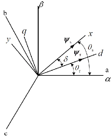
From the introduction to different reference frames, it can be seen that there are differences and connections between these reference frames. The relationship between different reference frames is shown as Fig. 2.1,ψs the stator flux linkage vector, ψr is rotor (magnet) flux linkage vector. The
angle between the stator and rotor flux linkages δ is the load angle when the stator resistance is neglected. In the steady state, δ is constant corresponding to a load torque, and both stator and rotor flux rotate at the synchronous speed. In transient operation, δ varies and the stator and rotor flux rotate at different speeds [8].
Fig. 2.1. The stator and rotor flux linkage in different reference frames.
In order to analyze different reference frames, a transformation will be used. The transformations for different reference frames are shown as below:
(1) The transformation of abc↔αβ
The conversion is known as Clarke Transformation. Assuming F represents the voltage, current and flux linkage, in
abc
reference frame are Fa, Fb, Fc and in αβ reference frame are Fα, Fβ. The11 3 /2
1
1
1
2
2
3
3
0
2
2
2
2
2
2
2
2
a
s s b
c
F
F
C
F
F
F
(1) 2 /3 2 1 0 21 3 2 2 2 2
1 3 2 2 2 2
a
b s s
c F F F C F F (2)
Where C is the coefficient before and after the transformation. For constant power conversion,
3 /2 2 /3
2
2
,
3
3
s s s s
C
C
, and for constant amplitude conversion, 3 / 2 2, 2 /3 1 3s s s s
C C .
(2) The transformation of αβ↔dq
The conversion is known as Park Transformation. Assuming F represents the voltage, current and flux linkage, in dq reference frame are Fd, Fq. The transformation is:
cos sin sin cos
d r r
q r r
F F F F
(3)
cos sin sin cos d r r q r r F F F F
(4)
(3) The transformation of xy↔dq
AssumingF represents the voltage, current and flux linkage, in xy reference frame are Fx, Fy. The
transformation is: cos sin sin cos x d y q F F F F
(5)
cos sin sin cos d x q y F F F F
12
The well-known dynamic equations of a three-phase PMSM can be written in the dqreference frame as follows:
sd
sd s sd e sq
sq
sq s sq e sd
d u R i
dt d u R i
dt
(7)Where usd and usq are the d- and q-axis stator terminal voltages, respectively, isd and isq are the d-
and q-axis stator currents, Rs is the resistance of stator windings, ωe is the rotor electrical angular
speed. The d- and q-axis stator flux linkages of the PMSM ψsd and ψsq have the form of:
sd d sd f
sq q sq
L i
L i
(8)Where Ld and Lq are the d- and q-axis inductances of the PMSM. ψf is the flux linkage generated by
the PMs.
The electromagnetic torque Te generated by the PMSM can be calculated by:
3
2
3
2
e sd sq sq sd
f sq d q sd sq
T
p
i
i
p
i
L
L i i
(9)Where p is the number of pole pairs. It can also be rewritten in terms of stator flux linkage and load angle, which is
3
2
sin
sin 2
4
e s f q s q d
d q
p
T
L
L
L
L L
(10)Where |ψf| is the magnitude of the stator flux linkage. The electromagnetic torque consists of two
terms. The first is the excitation torque, which is produced by the permanent magnet flux, and the second term is the reluctance torque. For a PMSM with saliency (Ld ≠ Lq), the difference between
the asymmetrical flux paths in the d- and q-axis produces the reluctance torque which is not present in a nonsalient-pole PMSM [6].
13 0
0
s s s s
s s s s
u R i d
u R i dt
(11)
Where usα and usβ are the α- and β-axis stator terminal voltages, respectively, isα and isβ are the α-
and β-axis stator currents, ψsαand ψsβ are the α- and β-axis stator flux linkages.
The electromagnetic torque
T
e can also be calculated by:
3 2
e s s s s
T p
i
i (12)According to different control theory, mathematical models in different reference frames are used for analysis. For example, conventional field-oriented control is preferably implemented in the dq
reference frame, while conventional direct torque control is preferably implemented in the αβ reference frame. A spatial illustration of the stator flux components in the αβ and dq reference frames is shown in Fig. 2.2 [6].
14
2.2 Comparison Between FOC and DTC Strategies for PMSMs
Table. 2.1. summarizes and compares FOC and DTC from the aspects of the controllers’ features, dynamic performance, steady-state behavior and implementation complexity [18].
Table. 2.1. Summary of the comparison between FOC and DTC [18]
Comparison property FOC DTC
Dynamic response Fast Very fast
Steady-state behavior Low ripple and distortion High ripple and distortion
Switching frequency Constant Variable
Parameter sensitivity High Low
Requirement of rotor position Yes No
Current control Yes No
PWM modulator Yes No
Coordinate transformation Yes No
Control tuning PI gains Hysteresis bands
Complexity and processing
requirements
Higher Lower
This thesis mainly focuses on the dynamic response and steady-state behavior. From Table. 2.1, it can be known that for dynamic response, DTC is faster than FOC. However, for the steady-state behavior, FOC is better than DTC.
In view of the deficiencies of the conventional DTC of PMSMs, researches and scholars from all over the world have conducted a series of studied and improvements and made a great progress. In the next subsection, there is a literature review on DTC of PMSMs.
2.3 Literature Review of Existing DTC Techniques
The DTC using hysteresis controllers to regulate the stator flux linkage and electromagnetic torque with only nonzero voltage space vector has been proposed in [8] and it shows a significant torque ripple. Large torque ripples will inevitably affect the stability of the low speed performance of the motor. Existing research has proposed many different ways to reduce torque ripples in the DTC based PMSM and induction machine drive systems [19-32]. Therefore, the corresponding research work on torque ripple investigation and reduction is also introduced in this review.
15
introduced into the torque regulator, and the zero-voltage vector is used to maintain the torque to reduce the torque ripple. This method has achieved a good result of torque ripple minimization and has further improved the conventional DTC. However, it missed the further discussion about how long the zero-voltage vector should be applied. For digital control system, when using the conventional DTC, the voltage space vector selected by the flux linkage and torque regulators is applied to the entire control cycle. Once a non-zero vector has been selected, it can not be controlled, which inevitably brings the torque ripple issue. Therefore, some researches have proposed a method to reduce the torque ripple from the perspective of controlling the acting time the voltage space vector. [20] V. Ambrozic presents a method to calculate the non-zero voltage vector acting time through the difference between the actual torque and torque reference combined with the equation of torque in a control cycle. The rest would be the acting time for zero voltage vector used for torque ripple minimization.
The conventional DTC only utilizes six non-zero voltage vector. However, synthesizing more voltage space vectors is becoming another method to achieve torque ripple minimization. This helps increase the control in the control cycle. In [21-24], the researchers make it possible to synthesize a higher number of voltage vectors with respect to conventional DTC scheme through using prefixed time intervals within a control cycle period. With the increase of the available voltage space vector, the torque error in the torque regulator can be divided into different levels. According to the magnitude of the torque error range, a suitable voltage space vector is selected from the synthesized voltage space vectors to compensate for the torque error. In practice, the extended switch table is pre-defined in the controller without extra calculation. Due to more voltage space vectors, multiple control of the motor flux linkage and torque can be achieved within one control cycle, thus increasing the control accuracy and effectively reducing torque ripple.
16
linkages. This method improves the control effect of the flux linkage and torque and achieves the purpose of reducing torque ripple.
Due to the hysteresis control, the sampling frequency of an inverter in DTC must be higher than that with FOC. Therefore, it is vital to determine the switching frequency of the inverter for DTC; taking into account that it varies with the operation point [28]. In [29] the relationship between the inverter switching frequency and the width of the hysteresis bands of the controllers was studied in detail, together with the impact of motor parameters and speed. Generally speaking, smaller torque hysteresis band will result in smaller torque ripple but higher switching frequency. However, this is limited by computational speed of digital control system and operational frequency of power switch.
Although synthesizing voltage space vectors and stator flux linkage section division can help to reduce the torque ripple, the number of voltage space vectors and sections are not endless. Some researchers have learnt from the idea of vector synthesis and sector division and made further advances. The basic idea is to use space voltage vector modulation (SVM) technology to synthesize an optimal voltage space vector based on the motor torque and flux control requirements [30-37]. This will accurately compensate the flux linkage and torque error, and finally achieve the purpose of reducing torque ripple [35]. Conventional switching-table-based DTC utilizes one of a limited number of voltage vectors with fixed magnitudes and positions in each control period. However, DTC-SVM can synthesize an arbitrary reference voltage vector within its linear range with multiple vectors in each sampling interval [36]. SVM-based DTC can calculate the required voltage vector to simultaneously regulate the stator flux and torque of the PMSM which significantly reduces the torque ripple with constant switching frequency. The caveat is the usage of the SVM increases the computational burden as compared to the conventional DTC [37].
In the past decades, modern control theories were widely used in power and dynamic control systems. Many new DTC controllers were realized by combining traditional DTC schemes with modern control methods such as fuzzy logic control, sliding mode and artificial neural network [28]. The development of the digital controller provides good conditions for the implementation of DTC methods based on modern control theory.
17
is well suited for nonlinear dynamic systems with uncertainties. Sliding mode control ideas have been investigated for the SVM-DTC of induction motors. They are characterized by the fact that enforcing a sliding mode leads to low sensitivity with respect to a class of disturbances and plant parameter variations [28]. In [38-39], variable structure control method is used for torque and stator flux control.
In addition to sliding mode and variable structure control, fuzzy logic control has also been applied to DTC [40]. The errors of the torque, stator flux linkage and flux linkage angular position of the PMSM are fuzzified into several fuzzy subsets. This is done to select a suitable voltage space vector to obtain fast torque response and smooth the torque and flux linkage ripples simultaneously. The stator flux linkage vector angle is also mapped to a single reduced 60 degree region. This is based on the symmetry of the control rules for each 60 degree flux linkage angular region. As a result, the torque response performance can be improved because of the minimization of the number of fuzzy reasoning rules and hence the reasoning time.
The neural network is well known for its learning ability and approximation to any arbitrary continuous function. Neural networks have recently shown good promise for application in power electronics and motion control system. It has been stated in the literatures that artificial neural network can be applied to DTC controller design, parameter identification and state estimation of motor control systems [28]. In [41], two kinds of neural network controllers were used to perform as the state selector of DTC for an inverter-fed IPMSM.The result indicates that it is possible to replace switching table of the DTC for permanent magnet synchronous motor by a neural network controller and achieve high torque dynamic response.
2.4 Principle of DTC
As aforementioned, DTC can achieve rapid control of the torque. In contrast to induction machines, there is no slip between stator and rotor of PMSMs. Therefore, the DTC used for induction machines cannot be directly applied to PMSMs. However, the angle between the stator flux linkages and rotor flux linkages, which is the load angle, is very closely related to the electromagnetic torque of PMSMs. Equation (10) with constant motor parameters, shows that the amplitude of torque depends on stator flux amplitude and load angle. Since the the reluctance torque exists in interior PMSMs, the d- and q-axis inductances will impact the torque.
18
3
sin
2
e s f
s
p
T
L
(13)Equation (13) implies that the torque increases with the increase of δ. If the amplitude of stator flux linkage ψs is kept constant and the load angle δ is controlled within the range of -90°-90°. Then, the
derivative of Equation (13) with respect to the load angle can be derived as:
3
cos
2
e
s f
s
dT
p
d
L
(14)The relationship between torque and load angle δ of surface PMSMs has been shown as Fig. 2.3.
Fig. 2.3 The relationship between torque and load angle δ of surface PMSMs.
From Fig. 2.3, shows within the range of -90°-90°, Equation (14) is always positive. This implies
that the increase of torque is proportional to the increase of the load angleδ. In other words, the stator flux linkage should be controlled in such a way that the amplitude is kept constant and the rotating speed is controlled as fast as possible to obtain the maximum change in actual torque [8].
However, for interior PMSMs, since Ld ≠ Lq, the derivative of the electromagnetic torque with
19
3
2
cos
2
cos 2
4
es f q s q d
d q
dT
p
L
L
L
d
L L
(15)In interior PMSMs the torque increases with the increase of the load angle δ due to the reluctance torque as can be observed Equation (15). It is necessary to discuss the relationship between the amplitude of stator flux linkage and the derivative of the torque. Fig. 2.4. shows the relationship between torque and load angle of interior PMSMs when the amplitude of stator flux linkage is at
0.5ψf, ψf, 1.5ψf, 2ψf.
Fig. 2.4. The relationship between torque and load angle δ of interior PMSMs.
Note that for the torque near the zero point, when ψs=2ψf, the derivative of torque is negative, so
DTC cannot be applied in this case. In order to assure it is always positive, Equation (15) should satisfy the condition below (16).
q
s f
q d
L
L
L
(16)20
voltage Va, Vb, Vc are determined by the status of the three power switches, which called Sa, Sb, Sc
here.
C
Sa Sb Sc
a
+
-
VDCV
aV
bV
cFig. 2.5. A voltage source inverter-fed PMSM drive system.
The Va, Vb, Vc can be presented in Equation (17) with the respect to Sa, Sb, Sc:
1 2 3 1 2 3 1 2 3a DC a b c
b DC b a c
c DC c a b
V V S S S
V V S S S
V V S S S
(17)
Through the different switching statuses, the controller generates eight voltage space vectors, six of them are non-zero voltage vectors, and the rest are zero voltage vectors, as Fig. 2.6. shows below. Each voltage space vector has the numerical label to show the status of power switches in order of
Sa, Sb, Sc. To achieve the stator flux trajectory circular, the stator flux vector space in the αβ
stationary reference frame is divided into six sectors equally, which is the dotted line in Fig. 2.6. The sector can be selected based on the position of the estimated stator flux, which can be obtained from the α-, and β-axis stator flux components, as Equation (18) shows below:
1 tan s s
(18)
21
Fig. 2.6. Voltage space vectors and sectors in the αβ reference frame.
For PMSMs, the stator flux vector in α-, and β-axis can be expressed by:
s t Vs t R is t dt
(19)If neglecting the voltage drop on the resistor, Equation (19) can be simplified as
0s t Vs t s t
(20)
22
Fig. 2.7. Illustration of the voltage space vectors effect on the torque and stator flux.
Assuming the PMSM is rotating at the counter-clock direction, the stator flux vector lies in Sector 1. This also assumes the stator flux vector is ψs at this moment. From Fig. 2.7, the variations of the
torque and stator flux is illustrated by applying different voltage space vector (V2, V3, V4, V5, V6). If
V2 is applied, it will make the stator flux rotate counter clockwise, which will increase the load
angle δ and stator flux magnitude. Therefore, according to Equation (10), the torque will increase. Similarly, if V5is applied, both the load angle δ and the stator flux magnitude will decrease, thus
torque will decrease. Again, when V3is applied, the load angle δ will increase but the stator flux
magnitude will decrease. Overall, the torque still increases because the weight of the load angle on the torque change is larger than that of the stator flux magnitude. Similarly, V6 reduces the load
angle δ but increase the stator flux magnitude. Although the other active voltage space vectors V1
and V4can also increase or decrease the stator flux magnitude to effect on the change of torque, the
signs of the associated torque variations are not consistent. That is why only four active voltage space vectors are used in the Sector 1.
23
Fig. 2.8. The control of stator flux linkage and torque.
For conventional DTC of PMSM, the closed-loop control of the stator flux linkage magnitude and torque is required. In the first proposed DTC of PMSM, the stator flux linkage and torque regulator were as follows [8]:
* *1
0
0
0
s s s s
(21)
* *1
0
1
0
e e e eT
T
T
T
(22)Where |ψs|* is the stator flux linkage reference, ϕ is the output of the stator flux linkage regulator.
If ϕ=1 means the stator flux linkage need to be increase, then according to the sector appropriate voltage space vector will be selected. Else, the stator flux linkage needs to be decreased. Te* is the
24
Table. 2.2. Switching table in the conventional DTC
τ
1
2
3
4
5
61 1
2
V
V
3V
4V
5V
6V
1-1
6
V
V
1V
2V
3V
4V
50 1
3
V
V
4V
5V
6V
1V
2 -15
V
V
6V
1V
2V
3V
425
Chapter 3
Investigations of FOC and DTC of PMSMs through Simulations
In this chapter, the simulation studies were investigated using the MATLAB/Simulink software for the comparison of FOC and DTC control performance of PMSMs. First, the simulation model of FOC is presented, then the simulation model of DTC is shown. In the end, comparison studies are conducted based on the simulation results.
3.1 Motor Parameters for Simulation of FOC and DTC
The PMSM under test is from Estun Automation. Table. 3.1. below shows the parameters of the servo PMSM.
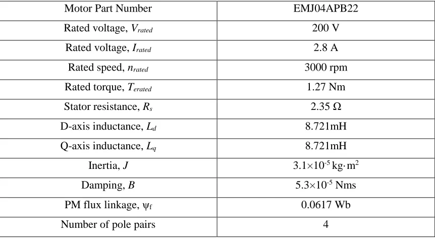
Table. 3.1. Motor Parameters for Simulation of FOC and DTC
Motor Part Number EMJ04APB22 Rated voltage, Vrated 200 V
Rated voltage, Irated 2.8 A
Rated speed, nrated 3000 rpm
Rated torque, Terated 1.27 Nm
Stator resistance, Rs 2.35 Ω
D-axis inductance, Ld 8.721mH
Q-axis inductance, Lq 8.721mH
Inertia, J 3.1×10⁻⁵kg·m2
Damping, B 5.3×10⁻⁵ Nms
PM flux linkage, ψf 0.0617 Wb
Number of pole pairs 4
3.2 Simulation Model of FOC of PMSM
Since the PMSM used for simulation is a surface-mounted PMSM, as mentioned before, the Id=0
control is equivalent to MTPA. In this simulation model, Id=0 combined with SVPWM have been
applied to achieve the FOC of PMSM.
3.2.1 PI controller tuning for current loop
26
1
q
sd s sd
sd e sq
d d d
sq s sq
sq e d sd f
q q q
L
di
R
u
i
i
dt
L
L
L
di
R
u
i
L i
dt
L
L
L
(23)Through Laplace transformation, applying the PI controller for current control, the equation for d- and q -axis voltage will be:
* *
* *
id
sd pd sd sd e q sq
iq
sq pq sq sq e d sd f
K
u K i i L i
s K
u K i i L i
s
(24)The zero of the PI controller block equals to the pole of the simplified filter model
1
s dq
R
sL
andthe current controller bandwidth can be made to be 1/10 of the switching frequency. The parameters of the current controller can be calculated as:
2 / 10 2 / 10
pdq B dq sw dq
idq B s sw s
K L f L
K R f R
(24)
3.2.2 PI controller parameter tuning for speed control
For PMSMs, the mechanical equations are shown as follows:
3 2
m e L m
e f sq d q sd sq
d
J T T B
dt
T p i L L i i
(25)If considering the inner loop fully following and with no load torque condition with TL0 and
0
sd
i , the equation above can be converted into:
3
( )
2
( )
f m sqp
s
i
s
Js
B
(26)27
2 / 10 3
2
2 / 10 3 2 sw p f sw i p f J f K p B f B K K J p
(27)3.2.3 Simulation Diagram for FOC of PMSM
From Fig. 1.7, the simulation model of FOC of PMSM in MATLAB/Simulink is built as Fig. 3.1. The simulation model consists of the function subsystem blocks including PI controller block, reference transformation block, SVPWM block, inverter block and PMSM. Through PI speed controller, the speed controller outputs the reference of q-axis current. Then the current PI controller outputs dq-axis reference voltages. Through inverse park transformation, abc frame reference voltages are obtained, and they can be the input of SVPWM block to generate the PWM switching signals that drive the PMSM.
The SVPWM block is shown as Fig. 3.2,
28
Fig
.
3
.1
.
Simu
latio
n
m
o
d
el
o
f
FOC
o
f
PMSM,
Id
=0
co
n
tr
o
29
3.3 Simulation model of DTC of PMSM
Figure 3.3 shows the conventional DTC of PMSM simulation model in MATLAB/Simulink. The stator flux linkage reference is set to be 0.078 Wb. Since the PMSM is surface PMSM, it will satisfy the requirement to keep the torque increases with the increase of load angle. Furthermore, the band width of hysteresis controller for flux is 0.004 Wb, which depends on the accuracy requirement for control performance, which can also be adjusted. The bandwidth of hysteresis controller for torque is 0.01 Nm.
Figure 3.4 shows the calculation of α- and β-axis stator flux linkages.
Fig. 3.4. α- and β-axis stator flux linkages calculation block.
30
Fig
.
3
.3
.
Diag
ram
o
f
co
n
v
en
ti
o
n
al
DT
C
o
f
31
Fig. 3.5. Switching table calculation block.
Figure 3.6. shows the actual stator flux trajectory from the simulation. It is similar with Fig. 2.8, which is also a circle with bandwidth. As mentioned before, the bandwidth is changed by adjusting the bandwidth of hysteresis controller. The amplitude of the α- and β-axis stator flux linkages are the reference given for the stator flux linkages.
32
3.4 Simulation Results and Analysis
The simulations were justified to obtain comparative results of FOC and DTC. The model runs at discrete mode with 100kHz sampling frequency, and the switching frequency is 10 kHz. There are two methods applied to compare the dynamic response and steady-state performance of FOC and DTC.
The first method is to make the speed reference continuously change. Here, the speed reference is generated by a function signal with different ramp. Also, the load torque is step changed from 0 Nm to 1 Nm at 0.1 second. Fig. 3.7. shows the speed response comparison of FOC and DTC, here the FOC requires more time to reach the reference point, but DTC follows the speed reference much faster.
33
Fig. 3.8. The torque response comparison of FOC and DTC with variable speed reference.
Figure 3.8. shows the torque response comparison of FOC and DTC. Although DTC still has a faster torque response than FOC, for the steady-state condition, the torque ripple of DTC is much larger than that of the FOC. Which is same as the conclusion from Table. 2.1.
The second method is to fix the load condition, which is first with no load, then with full load, at variable speed references to make the comparison of FOC and DTC. Variable speed references taken are: 500 rpm,800 rpm and 1000rpm. The load is applied at 0.1 second. Table. 3.2. shows the comparison between the time required to attain steady state and steady state torque ripple for FOC and DTC control with reference to results shown in Fig. 3.9. to Fig. 3.14.
Table. 3.2. Comparison at variable speed with full load.
Speed Reference Type of Control
Time to attain
steady state (ms)
(no load)
Time to attain
steady state (ms)
(full load)
Steady state
torque ripple (%)
500 rpm FOC 6.61 14.4 3.69
DTC 0.08 2.1 20.92
![Fig. 1.1. Suppliers of vehicle traction motors [4].](https://thumb-us.123doks.com/thumbv2/123dok_us/1350571.1167930/16.612.239.414.511.646/fig-suppliers-vehicle-traction-motors.webp)
![Fig. 2.2. Illustration of the stator flux components in αβ stationary and synchronously rotating dq reference frames [6]](https://thumb-us.123doks.com/thumbv2/123dok_us/1350571.1167930/28.612.217.446.354.568/illustration-stator-components-stationary-synchronously-rotating-reference-frames.webp)