AN APPLICATION OF OBSERVER FOR POSITION SENSORLESS STEPPER MOTOR DRIVES
NOR ARYMASWATI BINTI ABDULLAH
NOR ARYMASWATI BINTI ABDULLAH
This project report submitted in partial fulfilment of the requirements for the award of the degree of Master of Engineering
(Electrical - Mechatronics and Automatic Control)
Faculty of Electrical Engineering Universiti Teknologi Malaysia
iii
Dedicated with deepest love to:
My family, parents and siblings for their support, guidance and love.
ACKNOWLEDGEMENT
In the name of ALLAH, the Most Beneficent, The Most Gracious and the Most Merciful who has given me persistence in completing the project.
First of all, I would like to express my sincere gratitude to my project supervisor, Dr Salinda Buyamin, for the commitment, encouragement and valuable advice she provided me along the entire course of this project and report. Her rigorous views to do the project and inspire the idea to solve problems are precious for my future career.
I wish to thank my lab mates at Process Control Laboratory , Mr Alifa, Mr Rozaimi and Mr Azuni from Advanced Machine laboratory for the intellectual input and technical assistance .
I would like to thank to my colleague members, from MEM class of 2008/09 session for their support and advice.
A special thanks to my department, Malaysian Nuclear Agency who gives me the opportunity to continue my study.
v
ABSTRACT
A control method for stepper motor drives system can be made in open-loop circumstance which mean the system control did not require any feedback input signal in order to run the system. By applying the right sequences of pulses, the stepper motor capable to operate as other motion control. However, the performance of such system cannot be achieved to high level condition and demanded a feedback signal input to compensate the error produced while running the drive system. Therefore, a physical sensor or an encoder is placed in the motor system to obtain the feedback and form a close-loop system for error compensation. Nevertheless, the prices of these instruments are expensive, bulky and also may degrade the system performance. As a result this project presents a sensorless system in stepper motor drive system as an alternative to develop a close-loop system where the input signals are taken from voltage and current of the magnetic flux of the stepper motor.
ABSTRAK
Kaedah kawalan sistem motor stepper boleh dijalankan dalam keadaan lingkaran terbuka iaitu bermaksud sistem kawalan tidak memerlukan apa-apa suapbalik signal masukan semasa operasi dijalankan. Dengan mengaplikasikan urutan denyutan yang betul, stepper motor mampu beroperasi seperti kawalan gerakan yang lain. Walaubagaimanapun prestasi tersebut tidak boleh mencapai pada tahap yang tinggi. Ini memerlukan suapbalik masukan untuk mengimbangi kesilapan semasa sistem pemanduan beroperasi. Dengan itu, alat pengesan atau encoder diletakkan dalam sistem motor untuk menghasilkan suapbalik dan seterusnya membentuk sistem lingkaran tertutup sebagai pengimbangan kesilapan. Akan tetapi, harga alatan ini adalah mahal, bersaiz besar and juga boleh mengurangkan prestasi sistem. Oleh itu, projek ini mengetengahkan satu sistem tanpa alat pengesan dalam sistem pemanduan motor stepper sebagai alternatif membentuk sistem lingkaran tertutup di mana signal masukan diambil dari voltan dan arus magnetik fluk yang dihasilkan oleh stepper motor.
vii
TABLE OF CONTENTS
CHAPTER TITLE PAGE
DECLARATION ii
DEDICATION iii
ACKNOWLEDGEMENT iv
ABSTRACT v
ABSTRAK vi
TABLE OF CONTENTS vii
LIST OF TABLES x
LIST OF FIGURES xi
LIST OF ABBREVIATIONS xiii
1 INTRODUCTION
1.1 Background 1
1.2 Problem Statement 2
1.3 Objective of The Project 3 1.4 Scope of The Project 3
1.5 Methodology 3
2 LITERATURE REVIEWS
2.1 Introduction 6
2.2 Previous Research In Sensorless Technology 7
2.2.1
2.2.2
2.2.3
General Structured Unknown Input Observer
Robust Speed Control Of DC Servo Motor Based On Lyapunov’s Direct Method Sliding Mode Based Disturbance Observer For Motion Control
7
8
2.3 Observer 10
2.3.1
2.3.2 2.3.3 2.3.4
Model Reference Adaptive System (MRAS) Unknown Input Observer
Disturbance Torque Observer Instantaneous Speed Observer
11 13 13 14 2.4 Stepper Motor System 14
2.4.1
2.4.2
Stepper Motor Operation Type Of Stepper Motor
2.4.2.1 Variable Reluctance Stepper Motor 2.4.2.2 Permanent Magnet Stepper Motor 2.4.2.3 Hybrid Stepper Motor
15 17 17 18 19 2.5 Controller And Driver 21
2.5.1 2.5.2 2.5.3 2.5.4 2.5.5 2.5.6 2.5.7 Current Controller
Feedback Linearizing Controller Voltage Level Controller Neural Controller PID Controller L6208 Chip Driver Microstepping Driver 21 21 22 23 23 24 24
2.6 Encoder 25
2.6.1 2.6.2 2.6.3 2.6.4 Incremental Encoder Absolute Encoder Linear Encoder Rotary Encoder 26 26 27 27
3 PROJECT BACKGROUND
3.1 Introduction 28
3.2 Sensorless System Control 29
3.2.1
3.2.2 3.2.3
MRAS Observer
Mathematical modeling of stepper motor Stepper motor selection
ix
3.2.4 3.2.5
Stepper motor controller Stepper motor driver
35 37
4 SOFTWARE AND HARDWARE CONSTRUCTION
4.1 Characteristic Of Hybrid Stepper Motor 42
4.1.1 4.1.2 Circuit Representation Speed Characteristic 42 43
4.2 Simulation Implementation 46
4.2.1
4.2.2
Open Loop Simulation Close Loop Simulation
4.2.2.1 Transformation Of Four Phase Into Two Phase
4.2.2.2 MRAS Derivation
46 50 50
54
4.3 Hardware Implementation 57
4.3.1
4.3.2
Open Loop System Close Loop System
57 59
5 RESULTS AND DISCUSSIONS
5.1 Introduction 61
5.2 Open Loop System 61 5.3 Close Loop System (Sensorless System) 65
6 CONCLUSIONS AND FUTURE WORKS
5.1 Conclusion 69
5.2 Future Works 70
REFERENCES 71
LIST OF TABLES
TABLE NO. TITLE PAGE
3.1 3.2 3.3 3.4 4.1
Sequence and Direction of Rotation HSM Technical Specification of HSM
Full Step Mode Half Step Mode
Parameters for Driver Block and Hybrid Stepper Motor
xi
LIST OF FIGURES
FIGURE NO. TITLE PAGE
1.1 2.1 2.2 2.3 2.4 2.5 2.6 2.7 2.8 2.9 2.10 3.1 3.2 3.3 3.4 3.5 3.6 3.7 4.1 4.2 4.3 4.4 4.5
Flow Chart Of The Methodology
Block Diagram Of The Observer And Adaptive Controller
MRAS General Structure
From Controller (Logic Sequencer) To Motor Input Controller
Cross Sectional Of Stepper Motor Cross Section Of VR Stepper Motor
Permanent Magnet Stepper Motor Cross Section Cross Section Hybrid Stepper Motor
Special Features In HSM
L6208 Functional Block Diagram Block Diagram Of MRAS Estimator Stepper Motor Selected
Stepper Motor Configuration The Pin Diagram Of PIC Block Diagram For PIC16F8X
a)Unipolar Drive b) The Effect On Motor Performance Higher Supply Voltage And Larger Series Limiting Resistance
Typical Motor Winding Connections
Circuit Model For One Phase Of A Hybrid Stepper Simulink Block For Open Loop
Signal Generator Output
Look Under Mask For Four Phase HSM
a)Look Under Mask Of HSM b) Look Under Mask
4.7 4.8 4.9 4.10 4.11 4.12 4.13 5.1 5.2 5.3 5.4 5.5 5.6 5.7 5.8 5.9 5.10
Block Diagram Of The Whole System Basic Configuration Of MRAS
Simulink Block For Close Loop System Circuit Simulation For Stepper Motor Driver Waveform At Each Coil
Circuit Construction On a)Protoboard b)Strip Board a)Pair Of Optical And 8 Slot Disc Rotary Encoder b)Motor Shaft Was Slotted With Rotary Encoder Disc Voltage Phase, Current Phase And Torque Of Open Loop HSM
The Speed (Top) And Position (Bottom) Of The Open Loop HSM
The Speed (Top) And Position (Bottom) Of The MRAS System Without Feedback
The Comparison Between Open Loop System And Open Loop MRAS System Without Feedback For Speed (Top) And Position (Bottom)
Output Signal Of Rotary Encoder
The Speed (Top) And Position (Bottom) Of The Sensorless System With Feedback
The Comparison Between Open Loop System And Open Loop MRAS System With Feedback For Speed (Top) And Position (Bottom)
Current Phase Of Simulation Voltage Phase Of Simulation
Voltage Phase Of Hardware Implementation
xiii
LIST OF ABBREVIATIONS
ADC - Analog to Digital Converter BCD - Binary Coded Decimal CCW - Counter Clock Wise CW - Clock Wise
DC - Direct Current DIR - Direction
DMOS - Double-diffused Metal Oxide Semiconductor DQ - Direct Quadrature
DSP - Digital Signal Processing FPGA - Field- Programmable Gate Array GS - General Structure
HSM - Hybrid Stepper Motor IPM - Interior Permanent Magnet LTI - Linear Time-Invariant
MOSFET - Metal Oxide Semiconductor Field Effect Transistor MRAS - Model Reference Adaptive System
MSU - Microcontroller PC - Personal Computer
PID - Proportional Integral Derivative PLC - Programmable Logic Control PM - Permanent Magnet
PWM - Pulse Width Modulated UIO - Unknown Input Observer
LIST OF APPENDICES
APPENDIX TITLE PAGE A
B
Source Code For Embedded MATLAB Function In Simulink
Subsystem Of Simulation
74
CHAPTER 1
INTRODUCTION
1.1 Background
In recent years, a real robust of motion control in mechatronics technique is required in a very precise positioning and broad speed range applications. It means that drive systems are robust-controllable for precise positioning and broad speed range including from an ultra small to large positioning and ultra low to ultra high speed range. Both speed and positioning controller is very important for the performance improvement of drive systems. One of the important motion controls is to design a self reconfigurable controller such as electric motor controller for a hybrid electric vehicle application. This system detects the current sensors failure and will estimate the current successfully such that the motor continues working safely. The motor model is used for estimating the currents and the phase are estimated using Luenberger observer. The hall sensors with 60 degrees resolution have been used for positioning sensor. [1].
system feedback. Besides be able to remove space allocation for rotation-sensor hardware, it also is able to eliminate mechanical adjustment and maintenance. The other applications of the sensorless system are in city-scooter application, which has been design of a sensorless scheme suitable for general applications where low speed and standstill such as high speed operations are required. The observer detects the rotor magnet flux components in the two-phase stationary reference frame using the motor electrical equations [3]. The observer also used in solving the speed estimation problem in high-power railway traction applications, including the very low speed range. The full-order Luenberger observer design, based on voltage and current models, is used as the optimal alternative instead of the conventional method based on observer pole placement. [4].
1.2 Problem statement
3
1.2 Objectives of the project
The objectives of the project are determined as:
i) To investigate the performance of position control of stepper motor using PIC controller
ii) To study the application of sensorless in position control system of stepper motor
1.3 Scope of the project
The scope of the project includes:
i) To construct the hardware for stepper motor drive
ii) To apply the sensorless method of MRAS to the system
iii) To do performance comparison/analysis on position control of the system.
1.4 Methodology
5
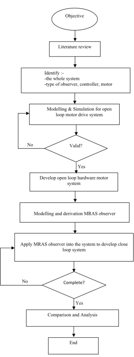
Figure 1.1 Flow Chart Of The Methodology
Objective
Literature review
Identify :- -the whole system
-type of observer, controller, motor
Modelling & Simulation for open loop motor drive system
Develop open loop hardware motor system
Modelling and derivation MRAS observer Valid?
Complete?
Apply MRAS observer into the system to develop close loop system
Comparison and Analysis
End
Yes No