University of Windsor University of Windsor
Scholarship at UWindsor
Scholarship at UWindsor
Electronic Theses and Dissertations Theses, Dissertations, and Major Papers
2014
CFD Simulation of Oil Jets with Application to Piston Cooling
CFD Simulation of Oil Jets with Application to Piston Cooling
GHASSAN (GUS) NASIF University of Windsor
Follow this and additional works at: https://scholar.uwindsor.ca/etd
Recommended Citation Recommended Citation
NASIF, GHASSAN (GUS), "CFD Simulation of Oil Jets with Application to Piston Cooling" (2014). Electronic Theses and Dissertations. 5214.
https://scholar.uwindsor.ca/etd/5214
This online database contains the full-text of PhD dissertations and Masters’ theses of University of Windsor students from 1954 forward. These documents are made available for personal study and research purposes only, in accordance with the Canadian Copyright Act and the Creative Commons license—CC BY-NC-ND (Attribution, Non-Commercial, No Derivative Works). Under this license, works must always be attributed to the copyright holder (original author), cannot be used for any commercial purposes, and may not be altered. Any other use would require the permission of the copyright holder. Students may inquire about withdrawing their dissertation and/or thesis from this database. For additional inquiries, please contact the repository administrator via email
CFD Simulation of Oil Jets with Application
to Piston Cooling
By
Ghassan Nasif
A Dissertation
Submitted to the Faculty of Graduate Studies
Through the Department of Mechanical, Automotive and Materials Engineering
in Partial Fulfillment of the Requirements for
the Degree of Doctor of Philosophy
at the University of Windsor
Windsor, Ontario, Canada
2014
ii
CFD Simulation of Oil Jets with Application
to Piston Cooling
By
Ghassan Nasif
APPROVED BY:
_____________________________________________________ H. Ge, External Examiner
Chrysler Group LLC, USA
_____________________________________________________ F. Ghrib
Department of Civil & Environmental Engineering
_____________________________________________________ G. Rankin
Department of Mechanical, Automotive and Materials Engineering
_____________________________________________________ B. Zhou
Department of Mechanical, Automotive and Materials Engineering
_____________________________________________________ R. Barron, Co-Advisor
Department of Mechanical, Automotive and Materials Engineering
_____________________________________________________ R. Balachandar, Co-Advisor
Department of Mechanical, Automotive and Materials Engineering
iii
DECLARATION OF CO-AUTHORSHIP/ PREVIOUS PUBLICATIONS
I. Co-Authorship Declaration
I hereby declare that this dissertation incorporates the outcome of research undertaken
under the co-supervision of Dr. Ronald M. Barron and Dr. Ram Balachandar from
University of Windsor. In all cases, I certify that I am the principal author and have had a
major role in the preparation and writing of the manuscripts.
I am aware of the University of Windsor Senate Policy on Authorship and I certify
that I have properly acknowledged the contributions of other researchers to my
dissertation.
I certify that, with the above qualifications, this dissertation, and the research to
iv
II. Declaration of Previous Publications
This dissertation includes three original journal papers and five conference papers.
The nature and extent of the co-authors’ contributions in these publications was to
provide supervision and advice in completing the research and preparing the manuscripts.
List of my publications are:
Dissertation
Chapter Publication title/full citation
Publication status
Chapter 5
Nasif, G., Barron, R.M. and Balachandar, R., 2014, "Simulation of Jet Impingement Heat Transfer onto a Moving Disc", Int. Journal of Heat and Mass Transfer.
Accepted for publication
Chapter 4
*Nasif, G., Barron, R.M. and Balachandar, R., 2014, "Heat Transfer Due to an Impinging Jet in a Confined Space", ASME, J. Heat Transfer, 136(11), doi: 10.1115/1.4028242
Published
Chapter 4
Nasif, G., Barron, R.M. and Balachandar, R., 2014, "Jet Impingement Heat Transfer: Stationary Disc", International Journal of Surface Engineering and Materials Technology (IJSEMT), 4(1), pp. 34-38.
Published
Chapter 5
Nasif, G., Barron, R.M. and Balachandar, R., 2014, "Heat Transfer Characteristics of Jet Impingement onto a Heated Disc Bounded by a Cylindrical Wall", Proceedings of the 10th International Conference on Heat Transfer, Fluid Mechanics and Thermodynamics (HEFAT), pp. 441-447, Orlando, FL, USA.
Published (proceedings)
Chapter 4 & 5
Nasif, G., Barron, R.M. and Balachandar, R., 2014, "Thermal Characteristics of Jet Impingement onto a Stationary and Moving Circular Disc", 22nd Annual Conference of the CFD Society of Canada, CFD 2014, Toronto, ON, Canada.
v
Chapter 4
*Nasif, G., Barron, R.M., Balachandar, R. and Iqbal, O., 2013, "Simulation of Jet Impingement Heat Transfer", Proceedings of ASME 2013 Internal Combustion Engine Division (ICED), Fall Technical Conference, Paper No. ICEF2013-19050, Dearborn, MI, USA.
Published (proceedings)
Chapter 5
Nasif, G., Barron, R.M. and Balachandar, R., 2013, "Jet Impingement Heat Transfer: Moving Disc", Proceedings of the 22nd National and 11th ISHMT-ASME Heat and Mass Transfer Conference, Paper No. HMTC1300891, Kharagpur, India.
Published (proceedings)
Chapter 4
Nasif, G., Barron, R.M., Balachandar, R. and Iqbal, O., 2013, "Simulation of Jet Impingement Heat Transfer Using VOF",21st Annual Conference of the CFD Society of Canada, CFD 2013, Sherbrooke, QC, Canada.
Presented in conference
*I am grateful to the American Society of Mechanical Engineers (ASME) for granting the
vi
I certify that I have obtained written permission from the copyright holders to include
the above published materials in my dissertation. An image of these written permissions
is included in the Appendix. I certify that the above material describes work completed
during my registration as a graduate student at the University of Windsor.
I declare that to the best of my knowledge, my dissertation does not infringe upon
anyone’s copyright nor violate any proprietary rights and that any ideas, techniques,
quotations, or any other material from the work of other people included in my
dissertation, published or otherwise, are fully acknowledged in accordance with standard
referencing practices.
I declare that this is a true copy of my dissertation, including any final revisions, as
approved by my dissertation committee and the Graduate Studies office, and that this
dissertation has not been submitted for a higher degree to any other University or
vii
ABSTRACT
This computational study is concerned with oil jet impingement heat transfer with the
aim to investigate and improve the heat transfer efficiency process of piston cooling.
Finite volume based computations using CD-adapco’s STAR-CCM+ are performed in this
study. One of the advantages of this commercial code is its ability to tackle problems
involving multi-physics and complex geometries. Generic models with fixed and
reciprocating moving discs are used in the first stage of this study to investigate the thermal
characteristics of the jet impingement. Subsequently, the information that has been acquired
from the first stage is used to successfully simulate a full-scale engine and estimate the
temperature profile and heat dissipation from the pistons with and without a cooling oil jet.
The computational results show that the radial extent of the stagnation region beneath
the jet is not uniform as stated in the literature, but is a function of the radial velocity
gradient in this region. Correlations describing the stagnation zone and local
Nusselt numbers have been developed, applicable over a wide range of Reynolds
numbers and Prandtl numbers. The effect of nozzle geometry is found to be insignificant
on thermal characteristics for long jets. For jet impingement onto a moving boundary, an
innovative methodology to accelerate the computational solution and reduce the cost in term
of CPU time has been developed and implemented.
Finally, the piston cooling process due to oil jet impingement is evaluated for the
Fiat-Chrysler full-scale 2.0 L Tigershark Inline 4-Cylinder gasoline engine. For this
specific simulation, the cooling jet reduces the volume average temperature, the
stagnation zone temperature, the maximum and minimum temperatures in the piston by
viii DEDICATION
I dedicate my efforts to:
ix
ACKNOWLEDGEMENTS
I would like to express my deep and sincere gratitude and appreciation to my advisors
Dr. R. M. Barron and Dr R. Balachandar for their invaluable support, technical guidance,
genuine interest, and generosity throughout the course of this study. Not only have they
been for me a source of great inspiration as teachers and researchers, but also an object of
admiration as a person as well.
I sincerely acknowledge the members of my doctoral committee, Dr. G. Rankin, Dr.
B. Zhao, Dr. F. Ghrib and Dr. H. Ge, for their valuable time and for serving on my
committee. I would like also to thank the Chrysler Canada/University of Windsor
Automotive Research and Development Centre (ARDC) for graciously extending the use
of their computing facilities. Special thanks go to Dr. M. O. Iqbal for his help during the
early part of this work.
I gratefully acknowledge the entrance scholarship that I received from University of
Windsor and the financial support from the Natural Sciences and Engineering Research
Council of Canada and Chrysler Canada Inc. through the NSERC Industrial Postgraduate
Scholarship program. Finally, I am grateful to all family members for their
x
TABLE OF CONTENTS
DECLARATION OF CO-AUTHORSHIP/ PREVIOUS PUBLICATIONS ... iii
ABSTRACT ... vii
DEDICATION ... viii
ACKNOWLEDGEMENTS ... ix
LIST OF TABLES ... xiii
LIST OF FIGURES ... xiv
NOMENCLATURE ... xvii
CHAPTER 1: INTRODUCTION ...1
1.1 Overview ... 1
1.2 Research Objective ... 3
1.3 Scope of this Dissertation ... 5
CHAPTER 2: LITERATURE REVIEW ...7
2.1 Introduction ... 7
2.2 Laminar and Turbulent Jets ... 8
2.3 Splattering of Turbulent Liquid Jets ... 13
2.4 Jet Impingement Flow Field ... 15
2.5 Radial Velocity Gradient at Stagnation Point ... 18
2.6 Liquid Jet Primary Breakup ... 20
2.6.1 Liquid Jet Breakup in Quiescent Medium ... 21
2.6.2 Liquid Jet Breakup in Crossflow Medium ... 23
2.7 Thermal Characteristics of Liquid Impinging Jets ... 26
2.7.1 Physical Mechanism of Convection ... 27
2.7.2 Stagnation Zone and Local Nusselt Number ... 29
2.7.3 Effect of Nozzle Configuration ... 35
xi
CHAPTER 3: COMPUTATIONAL METHODOLOGY ...39
3.1 Introduction ... 39
3.2 Governing Equation ... 40
3.2.1 Transient Term ... 41
3.2.2 Convective Term ... 41
3.2.2 Diffusion Term ... 43
3.3 Reconstruction Gradient ... 45
3.4 Reconstruction Gradient Limiting ... 46
3.5 Cell Gradients ... 47
3.6 Iterative Methodology ... 47
3.6.1 Basic Iterative Methods ... 49
3.6.2 Multigrid Methods ... 50
3.7 Segregated Models ... 51
3.7.1 Segregated Flow Model ... 51
3.7.2 Segregated Fluid Energy Model ... 57
3.7.3 Segregated Volume of Fraction Model ... 63
3.8 Turbulent Model ... 73
3.8.1 k-ω Turbulence Solver ... 79
3.9 Final Remarks ... 79
CHAPTER 4: HEAT TRANSFER DUE TO AN IMPINGING JET IN A CONFINED SPACE: STATIONARY DISC ...82
4.1 Introduction ... 82
4.2 Conjugate Heat Transfer (CHT) ... 83
4.3 Model Setup and Boundary Conditions ... 84
4.4 Validation of Numerical Simulation ... 88
4.5 Results ... 92
4.5.1 Effect of Nozzle Configuration (Long Jet) ... 92
4.5.2 Stagnation Zone Nusselt Number ( ) ... 95
4.5.3 Local Nusselt Number ( ) ... 103
4.5.4 Disc Temperature Profile ... 109
xii
CHAPTER 5: HEAT TRANSFER DUE TO A CONFINED JET IMPINGING
ON TO A MOVING DISC ...113
5.1 Introduction ... 113
5.2 Model Setup and Boundary Conditions ... 114
5.3 Results and Discussion ... 118
5.3.1 Moving Boundary without Jet ... 119
5.3.2 Moving Boundary with Jet ... 122
5.3.2.1 Initial Estimate of the Temperature Profile ... 124
5.3.2.2 Nusselt Number Profile ... 128
5.3.2.3 Disc Temperature Profile ... 133
5.4 Conclusions ... 138
CHAPTER 6: SIMULATION OF PISTON COOLING USING OIL JETS ...141
6.1 Introduction ... 141
6.2 Model Setup and Boundary Conditions ... 143
6.3 Results and Discussion ... 149
6.3.1 Domain Initialization ... 149
6.3.2 Nusselt Number Profiles ... 154
6.3.3 Piston Temperature Profile ... 157
6.4 Conclusions ... 162
CHAPTER 7: CONCLUSIONS AND RECOMMENDATIONS ...164
7.1 Conclusions ... 164
7.2 Recommendations for Future Work ... 166
REFERENCES ...168
APPENDIX ...175
xiii
LIST OF TABLES
Table 4.1: Input parameters for jet impingement onto a stationary disc ...86
Table 4.2: Summary of thermal characteristics for different nozzle geometries ...94
Table 4.3: Stagnation zone characteristics, for H = 60 mm ...101
Table 5.1: Input parameters for current numerical simulation ...115
Table 5.2: Surface average Nusselt number (averaged over one cycle) at solid-fluid interface without jet cooling, (a) ω = 210 rad/s, (b) ω = 630 rad/s ...120
Table 5.3: Surface average Nusselt number at solid-fluid interface, at two elevations from the nozzle exit; (a) = 20, (b) = 100 ...125
Table 5.4: Comparison of computed with the results from equations (4.2) and (2.40) ...127
Table 5.5: Angle of occurrence of the maximum and corresponding velocity gradient near the wall for the first three regions defined in Figure 5.3 (ω = 630 rad/s) ...132
Table 5.6: Surface average Nusselt number (phase-averaged over one cycle) at solid-fluid interface with the cooling jet: (a) ω = 210 rad/s, (b) ω = 630 rad/s ...135
Table 5.7: Surface average of steady-state temperature for the regions defined in Figure 5.3 ...136
xiv
LIST OF FIGURES
Figure 1.1: Oil squirter assembly ...3
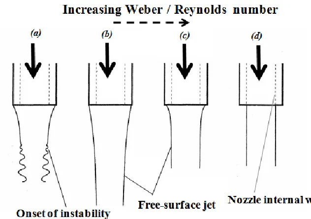
Figure 2.1: Schematic illustration of free surface jet structure with increasing Weber number (or Reynolds number) ...9
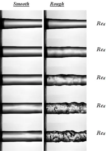
Figure 2.2: Surface profiles of a jet issuing from a smooth pipe (left), and a rough pipe (right), as a function of the Reynolds number ...12
Figure 2.3: (a) Splattering turbulent jet issuing from fully-developed nozzle showing radially travelling wave, = 28,000, ξ = 0.11, (b) Splattering turbulent jet issuing from fully-developed nozzle, = 48,300, ξ = 0.31, (c) Laminar impinging jet issuing from contoured orifice, = 51,000, d = 5.0 mm ...15
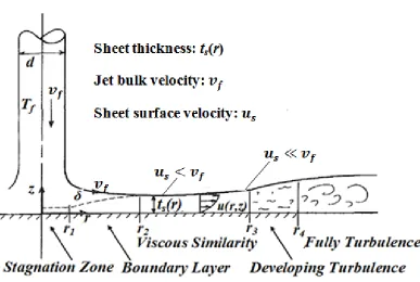
Figure 2.4: Jet and film flow showing hydrodynamic evolution ...18
Figure 3.1: (a) Convective boundedness criterion (CBC) on the three control volumes; upwind (U), central (C) and downwind (D), (b) Normalized variable diagram (NVD); upwind differencing (UD), downwind differencing (DD), central differencing (CD) and linear upwind differencing (LUD) ...67
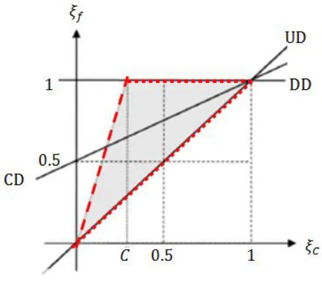
Figure 3.2: NVD shows the universal limiter boundaries. The dashed red boundary has a Courant number dependent slope . The case shown is for ...70
Figure 4.1: Computational domain and relevant boundary conditions ...84
Figure 4.2: Effect of domain confinement on local Nusselt number obtained for nozzle size d = 4.0 mm at = 15 and = 12000 ...89
Figure 4.3: Comparison of computed stagnation zone Nusselt number with correlation given by equation (2.39), for H = 60 mm ...90
Figure 4.4: Comparison of computed local Nusselt number with correlation given by equation (2.40); H = 60 mm, d = 2 mm ...91
Figure 4.5: Exit velocity profiles for three nozzles sizes ...93
Figure 4.6: Suppression of the velocity gradient in radial direction (velocity relaxation)
...93
Figure 4.7: Contours of radial velocity gradient and radial extent of the stagnation zone for = 1.0 mm at =60; (a) = 2000, (b) = 4000, (c) = 6000 and (d) = 8000 ...98
xv
Figure 4.9: Contours of radial velocity gradient and radial extent of the stagnation zone for = 4.0 mm at =15; (a) = 4000, (b) = 8000, (c) = 12000 and (d) = 16000 ...100
Figure 4.10: Dependence of: (a) stagnation point radial velocity gradient and (b) dimensionless radial velocity gradient, on the parameter ...102
Figure 4.11: Variation of stagnation zone Nusselt number with Reynolds number ....102
Figure 4.12: Local Nusselt number normalized by , H = 60 mm: (a) = 60, (b) = 30, (c) = 15 ...106
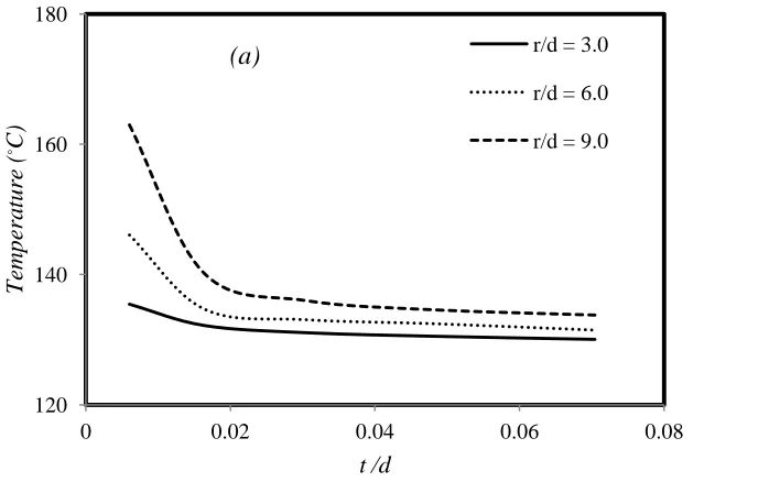
Figure 4.13: Temperature distribution across the fluid film at three different locations downstream of the stagnation point, H = 60 mm, = 12000: (a) = 30, (b) = 15 ...107
Figure 4.14: Temperature distribution at the interface between the oil sheet and impinging surface, H = 60 mm, = 12000: (a) = 30, (b) = 15 ...108
Figure 4.15: Distribution of radial velocity beneath the stagnation region (A): (a) d = 1.0 mm, = 8000, (b) d = 2.0 mm, = 16000, (c) d = 4.0 mm, = 16000 ....108
Figure 5.1: Computational domain and relevant thermal boundary conditions ...114
Figure 5.2: Motion profile over one cycle for two angular velocities of the disc; (a) 210 rad/s, (b) 630 rad/s ...116
Figure 5.3: Delineation of the nine regions at the fluid-solid interface ...118
Figure 5.4: Temperature profile in the disc without cooling jet; (a) ω = 210 rad/s, (b) ω = 630 rad/s ...120
Figure 5.5: Contours of mean radial velocity averaged over one cycle; (a) ω = 210 rad/s, (b) ω = 630 rad/s ...121
Figure 5.6: Evolution of liquid jet as disc moves towards its top position (TP), ω = 630 rad/s ...123
Figure 5.7: Steady-state temperature profile for stationary disc with cooling jet, at two elevations from the nozzle exit: (a) = 20, (b) = 100 ...124
Figure 5.8: (a) Horizontal section through liquid jet, at 2.0 mm before impinging point (velocity magnitude), (b) Solid-fluid interface (VOF) ...126
Figure 5.9: Surface (solid-fluid interface) average transient Nusselt number with cooling jet; (a) ω = 210 rad/s, (b) ω = 630 rad/s ...129
xvi
Figure 5.11: Contours of radial velocity and volume fraction of oil adjacent to the solid-fluid interface for two inner regions defined in Figure 5.3 (ω = 630 rad/s) ...131
Figure 5.12: Evolution of surface average temperatures at fluid-solid interface with physical time; (a) ω = 210 rad/s, (b) ω = 630 rad/s ...133
Figure 5.13: Final temperature distribution in the moving disc with the cooling jet; (a) ω = 210 rad/s, (b) ω = 630 rad/s ...134
Figure 5.14: Evolution of temperature profile at stagnation zone region (Region-1) for angular velocities 210 rad/s and 630 rad/s ...138
Figure 6.1: Computational domain and relevant boundary conditions ...144
Figure 6.2: Interfaces (yellow) between different parts inside the computational domain ...145
Figure 6.3: (a) Meshed domain; (b) Cross-sectional view through meshed domain ...145
Figure 6.4: (a) VOF contours for the entire computational domain after initialization; (b) Cross-sectional VOF contours passing through squirters and cooling jets ...147
Figure 6.5: (a) Velocity profile at nozzle exit; (b) Motion profile over one cycle for engine speed N = 2000 rpm ...148
Figure 6.6: Computational domain without oil sump, used for domain initialization ...150
Figure 6.7: Steady-state contours from transient simulation for the computational domain shown in Figure 6.6; (a) Velocity magnitude; (b) Pressure; (c) Temperature; (d) Turbulent kinetic energy ...151
Figure 6.8: Computational domain used to find the temperature profile in the solid piston with and without cooling jet ...152
Figure 6.9: Temperature and pressure profile as function of crank angle, extracted at cylinder/ crankcase interface (interface 3 shown in Figure 6.2) ...153
Figure 6.10: Solid piston configuration; (a) Entire piston; (b) External shell; (c) Internal shell ...154
Figure 6.11: Average Nusselt number at piston-fluid interface; (a) without cooling jet; (b) with cooling jet ...156
Figure 6.12: Computational domain (piston and two compression rings) with the relevant thermal boundary conditions ...157
Figure 6.13: Temperature profile in the piston without cooling jet, N =2000 rpm ...159
xvii
Nomenclature
Control volume face area
Control volume face area at fluid-wall interface
a Coefficient arising from finite volume discretization
Average of momentum coefficients
B Dimensionless velocity gradient defined by equation (2.11)
Coefficient in blended wall law defined by equation (3.89)
b Explicit contribution to discretized equation
Courant number
Coefficient in blended wall law defined by equation (3.88)
Coefficient related to cross-diffusion term in k-ω SST model
Constant, defined by equation (2.34)
Cg Constant, depends on geometry in equation (2.29)
cf Skin friction coefficient
cp Specific heat
Coefficient in blended wall law defined by equation (3.87)
Ddroplet Droplet diameter from capillary breakup
Cross-derivative term defined by equation (3.130), k-ω SST model
d Jet diameter at the exit of smooth pipe nozzle
Total energy
Wall function coefficients defined by equation (3.79)
xviii
Curvature correction factor in k-ω SST model
Roughness function
Functions defined by equations (3.136) & (3.139), k-ω SST model
Turbulent production
G(Pr) Boundary layer function of Prandtl number
Production of specific dissipation rate
Blending function defined by equation (3.146)
H Nozzle-to-target spacing
Total enthalpy defined by equation (3.64)
h Heat transfer coefficient, )
Local heat transfer coefficient defined by equation (3.93)
Internal energy
Thermal conductivity or Turbulent kinetic energy
Effective thermal conductivity defined by equation (3.68)
Lc Liquid jet breakup length
l Characteristic length, equal to d in this study
m, n Exponents in equation (2.29), range between 0 and 1
Control volume face mass flow rate
Local Nusselt number,
Local Nusselt number,
Stagnation zone Nusselt number,
xix
Function of Prandtl number defined by equation (3.81)
Prandtl number
Turbulent Prandtl number
Pressure
Q Volume flow rate of splattered liquid
Function used in calculation of , defined by equation (3.52)
Qs Volume flow rate of liquid jet
q Momentum flux ratio defined by equation (2.20)
q+ Dimensionless viscous dissipation
q"w Wall heat flux
Reynolds number based on nozzle diameter
r, z Cylindrical coordinates
Coefficient defined by equation (3.28)
Stagnation zone (or region) radius
Additional source specified by the user
St Stanton number defined by equation (2.36)
Sϕ Source term in equation (3.1)
T Temperature
Dimensionless temperature
Tf Temperature of incoming fluid
Wall-cell centroid temperature defined by equation (3.94)
Tref Reference temperature
xx
Tw Local wall temperature
t Time
Turbulent time scale defined by equation (3.134)
ts(r) Sheet thickness of wall jet
Mean components of velocity vector
Instantaneous components of velocity vector
Fluctuating components of velocity vector
Normalized wall-parallel velocity defined by equation (3.73)
Fictitious non-dimensional velocity defined by equation (3.83)
Wall-parallel component of velocity
Velocity components in radial and axial direction in cylindrical coordinate
Fluctuating components of velocity vector in cylindrical coordinate
Free surface velocity of liquid sheet
Shear velocity defined by equation (3.47)
Cell volume
Bulk velocity of incoming jet
Centreline velocity of incoming jet
Wed (or) Weliq Liquid jet Weber number defined by equation (2.18)
Wecf Gas crossflow Weber number defined by equation (2.17)
x, y, z Cartesian coordinates
xb Axial distance of breakup onset defined by equation (2.23)
xxi
Normal distance from the wall to the wall-cell centroid
Non-dimensional wall coordinate
Tensors & Vectors
A Control volume face area vector
a Solution vector in equation (3.35)
b Residual vector
Body force due to rotation
Body force due to gravity
Porous media body force
Vorticity confinement force
User-defined body force
I Identity matrix
n Normal vector to surface element dA
Heat flux vector
S Strain rate tensor defined by equation (3.128)
Laminar stress tensor
Turbulent stress tensor, defined by equation (3.42)
U Mean velocity vector
u Instantaneous velocity vector
W Rotation rate tensor defined by equation (3.138)
x Position vector
xxii
Greek Symbols
Coefficients in k-ω SST model
Volume fraction of the ith phase in the control volume
Scale factor defined by equation (3.22)
Coefficients in k-ω SST model
Blending function defined by equation (3.120)
Geometric weighting factor in equation (3.10)
Blending function in Kader's wall law defined by equation (3.91)
Diffusion coefficient in governing equation (3.1)
Rhie & Chow dissipation defined by equation (3.52)
Coefficient used in calculation at near wall locations
Δt Time step size
δ, δt Momentum and thermal boundary layer thickness
δstag. Stagnation zone boundary layer thickness
Von Karman constant
μ Dynamic viscosity
Turbulent viscosity
Effective viscosity,
ν Kinematic viscosity
ξ VOF normalized value
ξs Fraction of impinging liquid splattered, Qs/Q
xxiii
σ Liquid-gas surface tension
Inverse turbulent Schmidt number, coefficients used in k-ω SST model
Wall shear stress
ϕ Transported scalar property
ω Specific dissipation rate or Angular velocity
ωspl. Splattering parameter defined by equation (2.1)
1 CHAPTER 1
INTRODUCTION
1.1 Overview
Pistons in today’s motor vehicle engines perform a wide range of functions, e.g., they
transmit the force generated by combustion gases to the connecting rod, they support the
normal force applied against the cylinder walls while the cylinder pressure is conveyed to
the connecting rod and together with their sealing elements, they seal the combustion
chamber from the crankcase. The combustion chamber is the hottest part of the
engine. The piston is the bottom of the combustion chamber and it is the only part of the
chamber that is not cooled by the standard cooling system. Most of the heat is dissipated
from the piston through the piston rings into the cylinder walls, or through the wrist pins
and down the connecting rods. In the automotive industry, there is demand for increasing
engine performance in conjunction with decreasing free space in the engine compartment.
One of the consequences of increasing the engine power density is that it threatens the
structural integrity of the pistons at high engine loads, making them susceptible to
disintegration due to the thermal stress.
Internal combustion engine pistons can be cooled by oil, water or air. Air-cooling is
simpler from a design point of view, but lower specific heat per unit volume of air
requires very large quantities of air to be directed towards the piston. This involves bulky
ducting arrangements and an additional air compressor, which makes it less appealing
from a practical viewpoint. Water-cooling was applied to heavy, low speed engines for
2
difficulties with piping and sealing. Oil jet piston cooling is an alternative way to cool the
piston. The oil jet splashes the oil on to the underside surface of the piston, thus removing
the heat from the piston and effectively cooling it.
Impinging jets provide an effective manner to transfer energy or mass in many
industrial applications. A directed liquid or gaseous flow released against a surface can
efficiently transfer large amounts of thermal energy or mass between the surface and the
fluid. Jet impingement is characterized by very low thermal resistance and is relatively
simple to implement (Agarwal et al., 2011). In many applications, the conventional
cooling requirements are limited by other restrictive factors such as available space,
coolant selection, local environmental conditions and maximum allowable surface
temperature.
Over the past few years, the oil jet cooling technology has been adopted by many
automotive manufacturers to prevent overheating of the piston and to meet low emission
and high power density requirements. Knock reduction is also one of the positive
consequences of using oil squirters. A jet of pressurized engine oil is sprayed to the
underside of each piston to help dissipate the extreme heat generated during sustained
high rpm operation. An oil squirter or nozzle is mounted at an appropriate location in the
block to clear the piston skirt as shown in Figure 1.1. Each squirter is equipped with a
check valve to keep oil from draining back into the sump. The check valve has a spring
that is only activated at a certain engine rpm, i.e., at high oil pressure.
3
Figure 1.1: Oil squirter assembly (www.turbo-mopar.com)
1.2 Research Objective
Chrysler Canada/University of Windsor Automotive Research and Development
Centre (ARDC) is presently interested in improving the performance of oil squirters that
are currently used in engines manufactured by Fiat-Chrysler Automobiles. Given the
enormous importance of oil squirters and the potential for future opportunities, new
challenges have been identified that require a better understanding of the fundamental
principles of the application. The setup complexity and high cost of conducting
4
relatively less expensive Computational Fluid Dynamics (CFD) simulation methodology
for investigation of the jet cooling technology.
This dissertation aims to obtain an effective approach to evaluate the cooling process
of the piston by oil jet impingement without phase change. The oil jet is directed at a
small region on the underside of the piston where the maximum temperature is expected.
The objectives of this research are to:
Investigate the local convective heat transfer at the underside and exterior piston
walls with and without an impinging oil jet. The heat transfer coefficient will assist to
predict the temperature distribution in the piston and subsequently the heat transfer
efficiency of the cooling process.
Evaluate the effect of nozzle size, jet Reynolds number and moving boundary on the
cooling process.
Predict the maximum temperature that may occur in the piston to ensure that the
temperature does not exceed the recommended limits.
Estimate the heat dissipation throughout the different parts of the piston, i.e., piston
rings, piston pin and inner shell of the piston with and without cooling jet.
Provide a well-grounded computational methodology to simulate similar problems as
part of Fiat-Chrysler Automobiles ongoing engine research program. This study gives
5 1.3 The Scope of this Dissertation
The flow field in the current study involves significant complexity in term of
multi-physics, tight geometry, moving parts, etc. Many thermal and fluid variables interact in
this complicated process. Various meshing and mesh moving techniques are required,
including arbitrary sliding interface (ASI) of counter weights and mesh morphing to
replicate the linear motion of the target, i.e., disc or piston. Time dependent energy and
momentum equations need to be solved with small time increments to prevent the
smearing associated with numerical diffusion and preserve the sharpness of the oil-air
interface. Flow characteristics and wall heat transfer of conventional impinging jets
depend strongly on a number of aspects, such as confinement, nozzle geometry and flow
conditions at the nozzle outlet. This explains the significant amount of effort devoted
worldwide to this area of research.
Impinging jet is regarded as a method of achieving particularly high convective heat
transfer coefficients and therefore enhances the heat transfer from the target (i.e., the disc
or piston in this study). Using numerical simulation to predict the thermal characteristics
with the presence of oil jet cooling will significantly help to select the proper design
factors that will improve the performance of the engine. To achieve this goal, finite
volume based computations using CD-adapco’s STAR-CCM+ are performed in the current
study for a variety of thermal and flow conditions with the aid of high performance
computing (HPC). Correlations to predict the convective heat transfer coefficient are
deduced and a methodology to accelerate the computational solution and reduce the cost
in terms of CPU time is developed in the current study.
A general review for several aspects and some of the latest research reported in the
6
energy equation and to model turbulence and the dynamics of a set of immiscible fluids,
solution to the transport equations of the relevant parameters needs to be coupled with the
solver for the Navier-Stokes equations. In Chapter 3 we summarize the computational
methodology and the segregated solvers required in the current study. Prior to launching
a full-scale detailed investigation on the real engine, a generic model is used to enhance
our understanding of the underlying physics of the problem. The thermal characteristics
of jet impingement on to stationary and moving discs are investigated in Chapter 4 and 5,
respectively. The simulation results of the entire engine with and without oil squirters are
presented in Chapter 6. Transient simulation of Fiat-Chrysler’s full-scale 2.0 L
Tigershark Inline 4-Cylinder gasoline engine is used in our study. The convective heat
transfer coefficient distribution on the piston wall and the temperature contours are
computed to evaluate the performance of the cooling process by oil jet impingement.
Lastly, the dissertation ends by summarizing the conclusions and recommending a
7 CHAPTER 2
LITERATURE REVIEW
2.1 Introduction
This chapter reviews several aspects and some of the latest research on impinging
liquid jets that has a consequence for the jet heat transfer problem investigated in this
dissertation. The aim of this review is to provide a unified description of the fundamental
and the technological aspects of this subject. Even though the impinging jet flow field
constitutes a simple geometry, it poses extremely complex flow physics due to the
different flow regions associated with the jet impingement process.
In industrial applications, jet flows can be classified based on the miscibility of the
substances comprising the jet and surroundings, i.e., the ability of substances to mix and
form a homogeneous solution. Thus, two common jets can be identified; miscible jets
(referred to as submerged jets) or immiscible jets (referred to as unsubmerged or free
surface jets). An example of miscible flow is a gas jet flowing into air, whereas a liquid
jet issuing into the atmosphere is a case of immiscible flow. An immiscible jet has
unstable boundaries and the stream is vulnerable to primary breakup or deflection some
distance downstream from the nozzle. The range of such flow, that is, the distance over
which the flow remains intact, depends on the physical properties of the substances and
the amount of initial turbulence at the nozzle exit. The free surface type jet flow will be
employed in the current study since they are involved in the localized cooling of the
8
Although single-phase jets have been most extensively employed in industry,
two-phase jets are also important in some applications. Depending on the temperature
difference between the wall and the saturation temperature of the jet liquid, impingement
heat transfer may have two patterns; single-phase forced convection and forced
convective boiling. In the current study, the saturated temperature of the engine oil is less
than the temperature of the target (piston) and therefore convective transport without
phase change is considered in our simulations.
According to the existing literature, the wall heat transfer for impinging jets is mainly
determined by the specific flow and thermal condition of the issuing jet. The Nusselt
number is often used as a measure of the heat transfer because it describes the physics in
terms of fluid properties, making it independent of the target characteristics. The Nusselt
number is commonly given as a function of Reynolds number, , and Prandtl number,
, in the form .
2.2 Laminar and Turbulent Jets
Elison & Webb (1994) investigated the transport of fully-developed liquid jets
impinging normally on a surface for the flow regime based on the
nozzle exit conditions. The issuing jets were imaged for the full span of Weber and
Reynolds numbers and the observations are summarized schematically in Figure 2.1. For
very low Weber number (not shown in the figure), droplets begin to form at the nozzle tip
and are torn off due to the gravity. As Weber number or Reynolds number increases, the
droplets coalesce into a single stream attached to the nozzle exit. The stream exhibits
9
starting point of these instabilities moves downstream along the jet as the Weber number
increases (the point of onset of the jet instabilities in Figures 2.1(b-d) are beyond the
nozzle-to-plate spacing investigated by Elison & Webb, 1994). At low Weber number,
the liquid jet boundary coincides with the outside diameter of the nozzle tube due to the
surface tension effect. Therefore, the jet itself is larger than the internal diameter of the
nozzle as shown in Figure 2.1(a-b). As Weber number increases, the free surface
curvature at the nozzle exit increases and its diameter approaches the internal diameter of
the nozzle as shown in Figure 2.1(c-d).
Figure 2.1: Schematic illustration of free-surface jet structure with increasing Weber
number (or Reynolds number) (Elison &Webb, 1994)
Jets with a parabolic profile are normally produced by a laminar flow issuing from a
10
distribution of the velocity profile will persist if the target is within a few diameters
downstream from the nozzle exit. If the jet is long enough for viscosity to act, this profile
diffuses toward a uniform velocity profile as the jet moves to the target. For a longer jet
column and at , the downward jet is likely to be contracted due to the
gravitational acceleration and the surface tension effect, which becomes more significant
at low Reynolds number.
Generally, the piping systems that provide liquid to nozzles are often turbulent.
Turbulence is promoted by high flow velocities, low liquid viscosity, surface roughness
and cavitation. The perturbations will be carried into the issuing jet unless the pipe nozzle
has a very high contraction ratio. Turbulent jets have an elevated heat transfer coefficient
owing to both the direct effect of free stream turbulence on the boundary layer and the
more indirect effect of a nonuniform velocity profile on the stagnation point velocity
gradient. The increase relative to laminar theory may range from 30-50% (Lienhard,
2006).
The stagnation zone boundary layer is likely to remain laminar over a wide range of
jet Reynolds numbers, but turbulence in the impinging jet will tend to disrupt the thin
viscous region, elevating the heat transfer coefficient. This effect is well documented for
the stagnation zone in gas flow (Lowery & Vachon, 1975; Mehendale et al., 1991). For
turbulent liquid impinging jets, a well defined turbulent nozzle is that of a
fully-developed turbulent pipe flow. A liquid jet issuing from a tube of more than about 40
diameters in length without a terminating nozzle is a fully-developed turbulent pipe flow
if the Reynolds number exceeds about 2000-4000. The roughness of the pipe wall
11
such flows do not exceed 4-5% in the core of the flow (Pope, 2000). Other types of
nozzles may be less turbulent than pipe nozzles if they have a strong and well-contoured
contraction at the outlet. It is worth mentioning that the jet free surface may remain
laminar even with high Reynolds numbers as shown in Figure 2.2, whereas the wall
roughness of the pipe nozzle specifies the disturbance level in the jet free surface.
Several researchers have adopted the pipe nozzle as a standard for turbulent liquid
jets and the turbulence of such a jet is only defined by the jet Reynolds number and the
nozzle diameter. The correlations have usually fit data to the form suggested by laminar
theory, adjusting the lead constant and Reynolds number exponent. The Prandtl number
exponent is normally chosen to be constant within a certain range (see section 2.7.1).
Thus, the independent effects of free stream turbulence, Prandtl number and Reynolds
number are lumped together in such results to produce a simple engineering equation. For
this reason, the turbulence intensity parameter is missing in liquid jet impingement
correlations that predict the heat transfer coefficient. The turbulence intensity effect on
thermal characteristics will be further discussed in section 2.7.3.
In contrast to laminar profiles, which typically vary from uniform in long jets to
parabolic in short jets (with = 2 , where is the bulk velocity of the jet flow),
the velocity profile of turbulent pipe flow will likely vary between a uniform and mildly
nonuniform distribution. However, the centreline velocity may be still significantly
greater than the bulk velocity. For example, at = 4000 in a circular tube, / =
1.27, while at = 105, / = 1.18 (Lienhard, 2006). The effect of velocity profile
12
Figure 2.2: Surface profiles of a jet issuing from a smooth pipe (left), and a rough pipe
13 2.3 Splattering of Turbulent Liquid Jets
Turbulent liquid jets that impinge on solid surfaces often splatter violently, ejecting a
shower of droplets from the liquid film formed on the target surface. The mechanism of
the splattering was studied extensively by Bhunia & Lienhard (1994a,b), Lienhard et al.
(1992) and Errico (1986). Strong splattering can result in atomization of 30-70% of the
incoming liquid jet. The airborne droplets will no longer contribute to cooling the wall.
The splattering has no influence on the heat transfer in the stagnation region because the
droplets break away several diameters downstream of the stagnation point. Therefore,
when the jet splatters, the cooling performance declines only downstream of the
stagnation point. Lienhard et al. (1992) defined the fraction of impinging fluid splattered,
, as the ratio of the splattered flow rate, Qs, to the incoming flow rate, Q.
The disturbance in a turbulent impinging jet is carried into the radially spreading
liquid film. The turbulence has two contrary effects on the convective heat transfer in the
locations close to the stagnation region; first, the fluctuation in the flow tends to enhance
the mixing and elevates the convective heat transfer coefficient in the boundary layer
downstream of the stagnation zone and promotes turbulent transition of the thin liquid
film. The skin friction, , will be greater with a turbulent liquid sheet in comparison with
a laminar one. Stevens & Webb (1992) performed an experimental study to measure the
free surface of the spreading liquid sheet. They found that the free-surface speed begins
to drop at r/d ≈ 2.5 with the turbulent jet, sooner than predicted by laminar flow theory.
This is attributed to the increase of the skin friction due to the turbulence. Second, the
turbulence disturbs the surface of the incoming jet and this disturbance is carried into the
14
amplitude. If the initial disturbances are large enough, the amplified disturbance in the
spreading sheet can cause droplets to break away from the liquid sheet, resulting in
splattering (Lienhard, 2006).
Investigations by Errico (1986) and Lienhard et al. (1992) suggest that splattering is
only a consequence of the disturbances on the surface of the impinging jet, as shown in
Figure 2.3(a-b). On the contrary, as shown in Figure 2.3c, undisturbed laminar jets do not
splatter unless they are long enough to have developed significant disturbances from
Rayleigh instability. Bhunia & Lienhard (1994a) investigated splattering for downwards
turbulent water jets impacting solid targets. Their experiments cover Reynolds numbers
between 2700 < < 98,000, Weber numbers between 130 < Wed < 31,000, and
nozzle-to-target spacing between 0.2 < < 125. This study explicitly indicates that for a
turbulent jet, the amount of splattering is governed by the level of surface disturbances
present on the surface of the jet. At a given nozzle-target separation, the amount of
splattering depends mainly on the jet Weber number. An empirical correlation is given in
Bhunia & Lienhard (1994b) to predict the splattering ratio, as:
where is the splattering parameter, which characterizes the rms amplitude of
disturbance reaching the target. This parameter is defined as:
The jet Weber number in equation (2.2) is based on the bulk jet
velocity at the nozzle exit, , the nozzle diameter, d, and the liquid surface tension, .
15
Figure 2.3: (a) Splattering turbulent jet issuing from fully-developed nozzle showing
radially travelling wave, = 28,000, ξ = 0.11, (b) Splattering turbulent jet issuing from
fully-developed nozzle, = 48,300, ξ = 0.31, (c) Laminar impinging jet issuing from
contoured orifice, = 51,000, d = 5.0 mm (Lienhard, 2006)
2.4 Jet Impingement Flow Field
The initial region of the impinging jet, for large enough nozzle-to-target spacing, is
characterized by free jet behaviour. A free jet can be defined as a jet entering a large
container of quiescent fluid. When an axisymmetric free jet strikes a target, the flow field
can be reasonably divided into an outer inviscid region and an inner viscous boundary
layer. A very thin viscous layer initiates normal to the impingement axis and around the
16
to heat flow, where the convective heat transfer coefficient reaches a large amount.
Following impingement, the flow spreads thinner as it travels radially, the thickness of
the liquid film adjacent to the wall decreases with radius. This decrease will bring the
growing boundary layer into contact with the surface of the fluid film. The fluid film
thickness begins to increase at larger radii due to the viscous drag, which slows down the
flow and thickens the liquid layer. The hydrodynamics of this fluid film was theoretically
studied by Watson (1964), who divided the flow field of the wall jet into five consecutive
regions as shown in Figure 2.4; (1) the above mentioned stagnation zone region, (2) the
laminar boundary layer region, in which the viscous layer thickness is less than the liquid
film. In this region, the liquid film free surface is assumed to have the same velocity as
the incoming jet, (3) the viscous similarity region, in which the viscous boundary layer
extends through the liquid film, the surface velocity decreases as radius increases due to
the viscous drag, (4) the transition region and (5) the fully turbulent flow region.
Analytical analyses to predict a radial film flow were performed by Sharan & Hoshino
(1984), Liu & Lienhard (1989), Liu et al. (1991), Azuma & Hoshino (1984a,b,c,d) and
Lienhard (1995). These various studies are in relatively good agreement with one
another. A brief discussion of the results from these studies is provided below.
Near the point of impact, a small viscous region is formed, referred to as the
stagnation zone. The range of stagnation zone radius has been experimentally
approximated by 0.0 ≤ r/d ≤ 0.787. This region is often extremely thin; the 99%
momentum boundary layer thickness for axisymmetric jet flow is given from theory as:
17
where , is the bulk velocity of the incoming jet and d is the nozzle diameter. The radial
velocity gradient in equation (2.3) is evaluated just above the boundary layer region.
Following the stagnation zone, a laminar transition region begins, where the flow transits
to a laminar boundary layer. This region extends in the range 0.787 ≤ r/d ≤ 2.23. The
region of laminar boundary layer behaviour begins at r/d = 2.23 and extends up to r/d <
0.1773 , where the free-surface velocity of the liquid sheet equals to the bulk
velocity of the incoming jet. In this region, the boundary layer thickness is approximately
The velocity profile in this region is given by:
The viscous boundary layer reaches the surface of the liquid sheet at a radius r2given by:
Beyond r2, the free-surface speed decreases as:
The liquid sheet thickness, , in this region is given as:
The velocity profile in this region is obtained by using equation (2.5) with surface
velocity from equation (2.7) and boundary layer thickness equal to film sheet
18
The radii of onset of the turbulence and when the flow becomes fully turbulence have
been correlated from experiments (Liu et al., 1991) as:
respectively. In light of the above equations and due to the existence of the confined
boundary, the flow will not extend beyond the similarity region in our study.
Figure 2.4: Jet and film flow showing hydrodynamic evolution
2.5 Radial Velocity Gradient at Stagnation Point
The radial velocity gradient at the stagnation point has a significant influence on the
heat transfer coefficient (Vader et al., 1991 Burmeister, 1983; Donaldson et al., 1971).
19
whose results depend mainly on the radial velocity gradient of the inviscid flow near the
stagnation point. Therefore, the analysis of the viscous stagnation region requires first the
solution of the velocity field at the outer inviscid region from potential theory. It is
worthwhile at this point to introduce a dimensionless velocity gradient, which will be
used extensively in our study. This parameter is defined as (Lienhard, 2006):
The gradient is evaluated immediately just above the boundary layer.
An analytical solution for a uniform velocity profile of circular jets impinging
normally onto a surface was found by Shen (1962) and by Strand (1964). They evaluated
the dimensionless radial velocity gradient at the stagnation point as:
The radial velocity distribution at the stagnation region is evaluated from potential theory
as:
Wang et al. (1989) found for laminar jets that the radial velocity gradient at the
stagnation point is a linear function of parameter . Stevens & Webb (1991)
concluded that the radial velocity gradient at the stagnation point also has an important
effect on the heat transfer coefficient in turbulent jets. The parameter may be used
to functionally describe the stagnation velocity gradient in turbulent jets. Contrary to
laminar jets, the turbulence may result in a slight non-linear dependence of the velocity
20
The velocity gradient at the stagnation point is strongly dependent on the velocity
profile in the approaching jet. Stevens et al. (1992) carried out laser-doppler
measurements of the radial velocity gradient for several turbulent flow nozzles located a
distance of one nozzle diameter from the target. For a converging nozzle, the gradient
was found to be ≈ 2.3. This type of nozzle would be expected to have the most nearly
uniform velocity profile, and its stagnation point gradient is close to the uniform profile
theoretical value, i.e., = 1.83. Corresponding measurements for a fully-developed pipe
nozzle showed that ≈ 3.6 (Stevens, 1991), well above the theoretical value. One may
conclude that the variation in among nozzles can have significant effects on turbulent
jet heat transfer when the nozzle-to-target spacing is small. The effect of nozzle
configuration on heat transfer coefficient will be further discussed in section 2.7.3.
All liquid jets will approach a uniform velocity profile when nozzle-to-target spacing
increases, e.g., when > 5.0 (for water), because viscosity tends to eliminate the
radial gradients within about five diameters downstream of the nozzle (Stevens & Webb,
1992). Therefore, for all long jets, the radial velocity gradient at the stagnation
point tends to be uniform, i.e., → 1.83 (theoretical value).
2.6 Liquid Jet Primary Breakup
The next subsections discuss the deflection and primary breakup properties of round
liquid jets in the absence and presence of a crossflow. Different regimes related to the
primary breakup will be briefly presented. The discussion in this section is concerned
21 2.6.1 Liquid Jet Breakup in Quiescent Medium
Rayleigh (1878) was among the first to study theoretically the breakup of round
liquid jets. He postulated the growth of small disturbances that produce breakup when the
fastest growing disturbance attains an optimum wavelength of 4.51d. After breakup, the
cylinder of length 4.51d becomes a spherical drop, with Ddroplet = 1.89d. Rayleigh’s
analysis took into account surface tension and inertial forces but neglected viscosity and
the effect of the surrounding air. Weber(1931) later extended Rayleigh’s work to include
the effect of air resistance on the collapse of jets into drops. He found that air friction
shortens the optimum wavelength for drop formation. For a relative velocity of 15 m/s,
Weber concluded that the optimum wavelength becomes 2.8d and the drop diameter
becomes 1.6d. Thus the effect of relative velocity between the liquid jet and the
surrounding air is to reduce the optimum wavelength for jet breakup which results in a
smaller drop size. At higher jet velocities, breakup is caused by waviness of the jet. This
mode is associated with a reduction in the influence of surface tension and increased
effectiveness of aerodynamic forces. At even higher velocities, this aerodynamic
interaction causes irregularities in the previously smooth liquid surface. These
irregularities or disturbances in the jet surface become amplified and eventually detach
themselves from the liquid surface. Ligaments are formed which subsequently
disintegrate into drops. As the jet velocity increases, the diameter of the ligaments
decrease and the mean drop diameters become much smaller than the initial jet. At very
high relative velocities atomization is complete within a short distance from the discharge
orifice. A wide range of drop sizes is produced, with the mean drop diameter being
22
Laminar flow is promoted by low flow velocity, high liquid viscosity and the absence
of any flow disturbances. With laminar flow, the velocity profile varies across the jet
radius in a parabolic manner, rising from minimum value at the outer surface to a
maximum at the jet axis. If a laminar jet is injected into quiescent or slow moving air,
there is no appreciable velocity difference between the outer surface of the jet and the
surrounding air. Therefore, the necessary conditions for jet breakup by air friction
decreases. For long jets, surface irregularities develop that cause the jet to disintegrate
into relatively large drops.
Many studies followed the Rayleigh(1878) and Weber(1931) investigations of liquid
column breakup lengths and turbulent primary breakup properties at the surface of round
liquid jets, e.g., Wu et al. (1992, 1995), Wu & Faeth (1993, 1995), Dai et al. (1998) and
Sallam et al. (1999). An experimental study of turbulent liquid breakup lengths in still air
at standard temperature and pressure was carried out by Sallam et al. (2002). In this
study, the jet exit conditions were limited to non-cavitating water and ethanol flows, long
length/diameter ratio (greater than 40:1), jet exit Reynolds numbers of 5000–200,000, jet
exit Weber numbers of 235–270,000 and liquid/gas density ratios of 690 and 860, where
direct effects of viscosity were small. Three liquid column breakup modes were observed
in this investigation; first, a weak turbulent Rayleigh-like breakup mode due to the
capillary instability for < 300, where the liquid column breakup length, could be
correlated as:
Second, a turbulent breakup mode for when the drop diameter
23
liquid column itself. The underlying requirement for such breakup is that conditions at
the jet exit must be turbulent, and the liquid column breakup lengths could be correlated
as:
Third, an aerodynamic bag/shear breakup mode for > 30,000, when small scale
turbulence has disappeared and the liquid column is distorted in the cross stream
direction by large-scale turbulence. The breakup mechanism that occurs in this mode is
very similar to aerodynamic breakup of non-turbulent round liquid jets in gaseous
crossflows. In this regime, the liquid column breakup lengths could be correlated as:
The merging of turbulent primary breakup and secondary breakup occurs for
liquid/gas density ratios smaller than 500 (Wu & Faeth, 1993). For such conditions,
Sallam et al. (2002) stated that the aerodynamic effects on turbulent primary breakup are
likely to differ from the behaviour observed in their investigations, where the liquid/gas
density ratios is greater than 500.
2.6.2 Liquid Jet Breakup in Crossflow Medium
The present study is concerned with heat transfer as a consequence of jet
impingement in turbulent surroundings. This chaotic surrounding ensues because of the
high reciprocating motion of the piston inside the cylinder. Therefore, the intact jet will
be vulnerable to deflection or primary breakup before reaching the impingement surface
due to the strong motion and turbulence of the gas in the contiguous ambient
24
significant role in primary breakup of the liquid jet in crossflow. These are the
thermodynamic densities of the liquid and gaseous phases, dynamic viscosities of the
liquid and gaseous phases, diameter of the nozzle, velocity of the liquid jet at the nozzle
exit, the normal velocity component of the gaseous phases to the liquid column and the
interfacial surface tension. The following dimensionless groups are relevant to primary
breakup of the liquid jet:
where the subscripts l and g refer to the liquid and gaseous phases, respectively.
The subject of a liquid jet in crossflow has been the focus of several experimental
studies with the primary objective of understanding the phenomenon better and proposing
physical models for liquid breakup. Various regimes of liquid breakup have been
observed for round liquid jets in crossflow, and the effects of variation in physical
variables that characterize both the liquid jet injection and crossflow have been
investigated in these studies (Hsiang & Faeth, 1995; Mazallon et al., 1999; Sallam et al.,
2004; Lee et al., 2007; Pai et al., 2008).
Wu et al. (1997, 1998) provided a phenomenological model for jet penetration based
on their own experiments. Their work has become one of the key referenced works in this
25
balance to obtain the jet trajectory using a regression analysis. Their measurements were
done at normal temperatures and pressures with q ranging from 4 - 185 and crossflow
subsonic Mach numbers of 0.2 to 0.4. They provided the following correlations:
The formation of ligaments and drops along the liquid jet surface were studied
experimentally by Sallam et al. (2004) using round non-turbulent liquid jets in air
crossflow at normal temperature and pressure. Test conditions included water, ethyl
alcohol, and glycerol jets injected normal to the crossflow for the following ranges of test
variables; crossflow Weber numbers of 0 – 2000, liquid/gas momentum flux ratios of q =
3 – 8000, liquid/gas density ratios of = 683 – 1033, and Ohnesorge numbers of Oh
= 0.003 – 0.29. These investigations revealed that the effect of crossflow on primary jet
breakup is weak for velocities corresponding to low Weber number, ≤ 4. The liquid
jet column is somewhat deformed, to yield an ellipsoidal cross section, and may be
deflected in the direction of the crossflow velocity. This behaviour is caused by reduced
gas pressures along the sides of the jet due to acceleration of the gas across the liquid jet
associated with lateral motion of the liquid jet which is eventually stabilized by surface
tension. The increased drag force due to the flattened shape of the liquid jet enhances its
tendency to be deflected due to the gaseous crossflow.
Sallam et al. (2004) showed that the transitions between the various breakup regimes
26
velocities for q < 8000. Transitions to different breakup regimes, i.e., bag, multimode,
and shear breakup, occurred at = 4, 30, and 110, respectively. They also concluded
that there were two regimes for both the onset of ligament formation along the liquid
surface and for the variation of ligament diameter as a function of distance from the
nozzle exit along the liquid surface. First, an initial transient regime associated with the
growth of a shear layer thickness near the liquid surface that supplies liquid to the base of
ligaments and, second, a quasi-steady regime where the shear layer thickness reaches its
maximum possible growth within the confines of the round liquid jet and has a thickness
that is a fixed fraction of the liquid jet diameter.
Pai et al. (2008) performed a computational study of a liquid jet in crossflow using
the spectrally refined level-set method. This study revealed that for a constant crossflow
Weber number, sizes of liquid surface disturbances on the windward side of the liquid jet
decrease with increasing liquid Weber number, while the jet penetrates deeper into the
domain with increase of the momentum flux ratio, q.
2.7 Thermal Characteristics of Liquid Impinging Jets
In this section, we will introduce a general physical description of the convection
mechanism and continue to describe the dimensionless parameters that characterize the
convective heat transfer. A brief description of the empirical correlations found in the
available literature that are used for prediction of the Nusselt number will be reviewed as