Compact Low Profile Broadband Rectangular
Patch Antenna
Javed K. Sayyad1, R. M. Autee2, Anurag Nigam3
Dept. of Electronics and Telecommunication, Deogiri Institute of Engineering and Management Studies,
Aurangabad (MS), India1
Assistant Professor & H.O.D, Dept. of Electronics and Telecommunication, Deogiri Institute of Engineering and
Management Studies, Aurangabad (MS), India2
Assistant Professor, Dept. of Electronics and Telecommunication, Deogiri Institute of Engineering and
Management Studies, Aurangabad (MS), India3
ABSTRACT: In this paper, a design of compact broadband rectangular patch antenna with double U-slots for broadband operation is presented. The antenna geometry is fed with a coaxial line feeding technique using SMA connector. The feed is connected in between the two arms of U-slots. The two slots are created on patch which is placed on the thin dielectric substrate of FR4 material with dielectric constant of 4.4 and the overall dimensions of proposed antenna is 69 mm × 62 mm × 1.6 mm. The proposed antenna geometry’s performance is investigated in the frequency range of 5 GHz to 10 GHz. This geometry exhibits resonance between 7.6 GHz to 9.2 GHz. In this work we have presented broadband rectangular patch antenna with U-slot which excites single broadband operation with around 1.6 GHz (20%) bandwidth and gain greater the 5 dB. Higher bandwidth at resonant frequency was obtained as compared to the conventional patch antennas. The proposed geometry was fabricated and tested for its validation. Measured results using network analyser fairly matches with the simulated values.
KEYWORDS: Compact Low Profile Antenna, Microstrip Antenna (MSA), Slotted Antennas, U-Slot, Broadband Antenna.
I. INTRODUCTION
Conventional microstrip antennas in general have a conducting patch printed on a grounded microwave substrate, and have the attractive features of compact, low profile, light weight, easy fabrication, and conformability to mounting hosts [1]. However, microstrip antennas inherently have a narrow bandwidth & lower gain but for the broadband applications the larger bandwidth is always demanded. In addition, applications in present-day mobile communication systems usually require smaller antennas in order to meet the miniaturization requirements of mobile units. Thus, size reduction and bandwidth enhancement are becoming major design considerations for practical applications of microstrip antennas. For this reason, studies to achieve compact and broadband operations of microstrip antennas have greatly increased.
Much significant progress in the design of compact microstrip antennas with broadband, dual-frequency, dual polarized and gain-enhanced operations have been reported over the past several years. In addition, various novel broadband microstrip antenna designs with dual-frequency, dual-polarized, and circularly polarized operations have been published in the open literature.
In this work, compact low profile Broadband rectangular patch antenna has been investigated thoroughly for exciting broadband with a gain nearly 6 dB. Although, the proposed geometry exhibits multiple S11 bands, but only one
Section II presents the related work on broadband microstrip antenna (MSA). Section III presents basic geometry of the proposed antenna. Optimization of the final geometry is presented in Section IV. Experimental validation of the work is presented in Section V. The conclusion and possible extension of the work is presented in Section VI.
II. RELATED WORK
Initially, the microstrip antennas were developed only for the space communication, but today due to their advantageous nature, these are used in government as well as in some commercial applications [3]. In trans-receivers, planar antennas play a vital role in the field of wireless communications. Some of them are microstrip patch antennas, folded dipole antennas, and slot antennas with each type having their own properties and usage. Among all these planar antennas the microstrip patch antennas have more advantages and better prospects, such as they are lighter in weight, low volume, low profile, smaller in dimension, ease of fabrication and conformity. Moreover, these microstrip patch antennas can provide dual and circular polarizations, dual-frequency operation, frequency agility, broad band-width, and feed line flexibility, and beam steering & omni-directional patterning also [6].
However, the serious problem of patch antennas is their narrow bandwidth due to surface wave losses, lower gain, low cross polarization and large size of patch for better performance and also narrow scanning range, and due to these problems it has created a need for an antenna with an enhanced bandwidth and gain. To realize a broad bandwidth & high gain, many antennas using the various techniques have been reported [7-20] with dual and multiple bands. For example, by using the phase array patch structures, the multilayered structures or the parasitic radiators, it is possible to design the patch antennas with a broad bandwidth [5-9].
III.PROPOSED ANTENNA
The conventional rectangular microstrip patch antenna is shown in Fig. 1 whereas modified rectangular patch, modified ground plane and proposed microstrip patch antenna with coaxial line feeding are shown in Fig. 1, and its optimized dimensions are listed in Table 1. In this proposed design, on a rectangular patch, two U-Slots are added to excite broad resonance band and also to enhance the gain and bandwidth of resonance band. The proposed geometry was designed and optimized on the substrate of glass epoxy (FR4) with thickness of 1.6 mm, dielectric constant of 4.4, and a loss tangent equal to 0.01. The antenna is simulated using Ansoft’s High Frequency Structure Simulator (HFSS) v.13 which is electromagnetic simulation software [22]. The detailed optimization procedure of the proposed antenna and its optimum dimensions, and characteristics are presented in this section.
Table 1: Dimensions of the optimized geometry
IV.GEOMETRY OPTIMIZATION
In this section parametric study is conducted to optimize the proposed antenna geometry. The key design parameters used for the optimization are length of the outer & inner U-slot arms, width of the outer & inner U-slot arms, gap between outer & inner slots. The detailed analysis & effect of these parameters on the geometry performance is investigated in the following subsections. All simulations were carried out with the help of HFSS v.13 software. The optimized dimensions of proposed antenna are shown by Solid lines of red colour in following graphs.
A] Effect of Length of Inner U-Slot (Ls1)
The length of inner u arms is changed from 21 mm to 23 mm in steps of 1 mm keeping all the parameters constant. The effect of length variation on reflection coefficient (S11) and gain characteristics of antenna are shown in figure 2. From
this study it can be noticed that the maximum gain of greater than 5 db was obtained.
Figure 2: Reflection and gain Vs Frequency characteristics
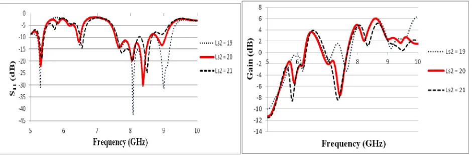
B] Effect of Length of Outer U-Slot (Ls2)
In this case, the length of outer U-arm was varied from 19 mm to 21 mm in steps of 1 mm with all other parameters kept constant. The results (S11 and gain Vs. freq.) are presented in Figure 3. From figure it may be noted that the optimum results can be obtained
for Ls2 = 20 mm.
Parameter Lg Wg L W Ls1 Ws1 L S2 WS2 d
C] Effect of Width of Inner U-Slot (Ws1)
In another effort, the width of outer U-slot arm is varied from 0.75 mm to 1.25 mm in steps of 0.25 mm keeping all the parameters constant. From these variations it is observed that the increase in the width of inner slot results in the drop of performance of antenna. From Figure 4 it can be noticed that the geometry exhibits optimum performance for Ws1= 1 mm.
Figure 4: Reflection and gain Vs Frequency characteristics
D]Effect of Width of Outer U-Slot (Ws2)
Here, the effect of outer U-slot’s width on geometry performance was investigated. The width of these two arms is changed from 1.75 mm to 2.25 mm in steps of 0.25 mm keeping all the parameters constant. From following figures it is important to note that the optimum results with higher gain & better reflection coefficient characteristics (S11)) are obtained at the Ws2= 2 mm.
Figure 5: Reflection and gain Vs Frequency characteristics
E] Effect of Spacing between Two U-Slots (d)
Figure 6: Reflection and gain Vs Frequency characteristics
V. EXPERIMENTAL VALIDATION OF THE GEOMETRY AND DISCUSSIONS
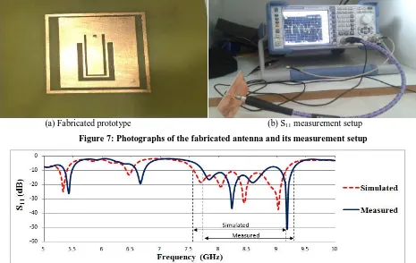
The basic geometry of the U-slots microstrip antenna shown in Figure 1 with its optimized dimensions presented in Table 1 was fabricated and tested. The substrate used for the fabrication of antenna is the FR 4 glass epoxy material with the thickness of 1.6 mm,
dielectric constant (εr) of 4.4, and the loss tangent (tan (δ)) = 0.01. A photograph of the fabricated prototype antenna is shown in
Figure 7 (a) and its reflection coefficient characteristics (S11) measurement setup is shown in Figure 7 (b). Reflection coefficient
characteristics (S11) of measured and simulated values are compared in Figure 8. The measured results fairly agree with the
simulated values.
(a) Fabricated prototype (b) S11 measurement setup
VI.CONCLUSION AND FUTURE WORK
In this paper, a microstrip antenna with broadbands loaded by two slots has been presented. The addition of U-slots on patch geometry helps in achieving proper bandwidth, gain, and radiation characteristics. The proposed antenna offers broader impedance bandwidth at resonant frequency as compared to the conventional patch antenna. The operating frequencies of the proposed antenna may be fine tuned by changing the slot dimensions and gap between them. Further study includes analysis of the antenna for its modeling and possible enhancement of bandwidth at first resonance. The future work includes the investigation of effect of patch and outer U-slot location on improvement of bandwidth as well as gain of double U-slot antenna with the multiband operation.
REFERENCES
[1] K. L. Wong, “Design of Nonplanar Microstrip Antennas and Transmission Lines”, Wiley, New York, 1999.
[2] Ahmed Khidre, Kai-Fong Lee, Atef Z. Elsherbeni, and Fan Yang, “wideband dual beam U-slot Microstrip antenna” IEEE Transactions on Antennas and Propagation, vol. 61, no. 3, pp. 1415-1418, 2013.
[3] R. Garg, P. Bhartia, I. Bahl, and A. Ittipiboon,” Microstrip Antenna Design Handbook”, Boston, MA: Artech House, 2000. [4] C. A. Balanis, “Antenna Theory: Analysis and Design”, 3rd Edn. New York Wiley, 2005.
[5] Tanvir Singh Buttar, Narinder Sharma, “A Review on Bandwidth Enhancement Methods of Microstrip Patch Antenna,” International Journal of Emerging Technologies in Computational and Applied Sciences, vol. 9, no. 3, pp. 276-279, 2014.
[6] Mithila R. Ghuge, A.P.Khedkar, Prathamesh U. Indulkar, “A Comparative Study of Gain Enhancement Techniques for Microstrip Patch Antenna,” vol. 3, no. 1, pp. 513-518, 2014.
[7] Kin-Fai Tong and Ting-Pong Wong, “Circularly Polarized U-Slot Antenna,” IEEE Transactions on Antennas and Propagation, vol. 55, no. 8, pp. 2382-2385, 2007.
[8] Pei-Yuan Qin, Andrew R. Weily, Y. Jay Guo, and Chang-Hong Liang, “Polarization Reconfigurable U-Slot Patch Antenna,” IEEE Transactions on Antennas and Propagation, vol. 58, no. 10, pp. 3383-3388, 2010.
[9] Amit A. Deshmukh and K. P. Ray, “Broadband Proximity-Fed Modified Rectangular Microstrip Antennas” IEEE Antennas and Propagation Magazine, vol. 53, no.5, pp. 41-56, 2011.
[10] Kin-Lu Wong, Chia-Luan Tang, Jyh-Ying Chiou, “Broad-Band Probe-Fed Patch Antenna with a W-Shaped Ground Plane” IEEE Transactions on Antennas and Propagation, vol. 50, no. 6, pp. 827-831, 2002.
[11] Hsing-Yi Chen and Yu Tao, “Performance Improvement of a U-Slot Patch Antenna Using a Dual-Band Frequency Selective Surface With Modified Jerusalem Cross Elements,” IEEE Transactions On Antennas And Propagation, vol. 59, no. 9, pp. 3482-3486, 2011.
[12] Ahmed Khidre, Kai-Fong Lee, Atef Z. Elsherbeni, and Fan Yang, “wideband dual beam U-slot Microstrip antenna” IEEE Transactions on Antennas and Propagation, vol. 61, no. 3, pp. 1415-1418, 2013.
[13] G. A. Bidkar, P. V. Hunagund, R. M. Vani, S. N. Mulgi and P. M. Hadalgi, “Low cost slotted microstrip line fed shorted patch antenna”, Int. J. Electron. Commun. Eng. & Technology, vol. 2, pp. 11-16, 2011
[14] R. C. Hadarig, M. E. de Cos and F. Las-Heras, “Research article: microstrip patch antenna bandwidth enhancement using AMC/EBG structures,” Int. J. Antennas Propagat., vol. 2012, pp. 1-6, 2011
[15] K. L. Wong and W. H. Hsu, “Broadband triangular microstrip antenna with U-shaped slot,” Electron. Lett. 33, pp. 2085–2087, 1997.
[16] Xu-bao Sun, Mao-yong Cao, Jian-jun Hao, Yin-jing Guo, “A rectangular slot antenna with improved bandwidth,” Int. J. Electron. Commun. (AEÜ), vol. 66, pp.465– 466, 2012.
[17] Subhajit Sinha, Biswarup Rana, Chandan Kumar Ghosh, S. K. Parui, “A CPW-Fed Microstrip Antenna for WLAN Application” Procedia Technology vol. 4, pp. 417–420, 2012
[18] G. F. Khodaei, J. Nourinia, and C. Ghobadi, “A Practical Miniaturized U-Slot Patch Antenna With Enhanced Bandwidth,” Progress In Electromagnetics Research B, vol. 3, pp. 47–62, 2008.
[19] Eduardo de las heras palmero, Zbyněk raida, Roberto lamadrid ruiz, “Quad-Band U-Slot Antenna for Mobile Applications,” Radio Engineering, vol. 15, no. 2, 2006.
[20] K. Gosalia and G. Lazzi, “Reduced size, dual-polarized microstrip patch antenna for wireless communications,” IEEE Trans. Antennas Propag., vol. 51, pp. 2182-2186, 2003.
[21] Kai-Fong Lee, Shing Lung Steven Yang, and Ahmed A. Kishk, “Dual- and Multiband U-Slot Patch Antennas” IEEE Antennas and Wireless Propagation Letters, vol. 7, pp. 645-647, 2008.