Material Based Structural Analysis of a Typical Landing Gear
Jeevanantham V1, Vadivelu P2 and Manigandan P3
1
Department of Aeronautical Engineering, Bannariamman Institute of Technology, Sathyamangalam, Tamilnadu, India
2
Department of Aeronautical Engineering, Bannariamman Institute of Technology, Sathyamangalam, Tamilnadu, India
3
Department of Aeronautical Engineering, Bannariamman Institute of Technology, Sathyamangalam, Tamilnadu, India
Abstract
Landing gear is a most important component in an aircraft system and it is observed from the literature that majority failures of aircraft structure takes place due to malfunction of landing gear. In this work, a typical landing gear of Boeing 747 aircraft is designed and meshed using ANSA software tool, and then analyzed for structural safety using ANSYS. The maximum possible load is given as design load. Landing gear is analyzed for the traditional metallic materials like Aluminum Alloy 7075, Alloys Steel 4340, Titanium 6AL-4V, Titanium 6AL-6V-2Sn, and Titanium 10Al-2Fe-3V. While comparing the results of the above mentioned materials, Titanium 10Al-2Fe-3V has the maximum factor of safety, and the minimum value of maximum stress developed and deflection. At last, from the analysis Titanium 10Al-2Fe-3V material is suggested to avoid structural failures of the modelled landing gear.
Keywords: Landing gear, Materials, Stress analysis, Deformation, Structural Safety.
1. Introduction
Aircraft landing gear is a most essential support of an aircraft during landing and ground operations. It is attached with primary structural members of an aircraft. Generally a landing gear has to bear heavy compressive load, drag load and side load. Drag load and side load values are very small when compared to compressive load. So, it is treated as one dimensional structure. During landing it is designed to absorb the landing impact energy such that the loads transmitted to the air frames are minimized. Apart from static strength, energy absorption is an important design criterion. For small aircrafts, a lip spring type of landing gear is normally sufficient to absorb the impact energy. For heavier aircrafts, oleo pneumatic landing gear strut are the normal choice. Landing gears are generally “safe life” components and are replaced many times during the service life of an aircraft. Traditional metallic materials used in landing gear structures are Aluminum, Titanium and steel alloys. Selection of material
depends on any considerations, which is in general be categorized as cost and structural performance.
2. Causes of Failure
The landing gear is a highly stressed structural part, and fracture or cracking or loss of integrity of the connection or attachment points can lead to serious consequence.
Some of the more common mechanically related causes for landing gear failures include:
• Improper rigging
• Improper repairs or maintenance
• Parts worn beyond their allowable service limits • Improper installation of parts
• Improperly secured parts
• Use of non-standard or unapproved parts • Failure or fatigue of parts
• Rupture of hydraulic lines.
• Failure of electrical wire connections, relays, contactors, and/or actuators
• Malfunctions of warning systems • Inoperative limit and safety switches, • Unlocks failed to release
• Down locks failed to engage.
• Wheels jammed or hung up in wheel wells. • Lack of lubrication
• Lack of hydraulic fluid
• Retraction of landing with tow bar still attached
Mechanical failure occurs due to Excessive deflection, Thermal shocks, Impact, Creep, Relaxation, Brittle fracture, Ductile fracture, Wear, Spring failure, Corrosion, Stress corrosion, Cracking and Fatigue.
gear. It has been established that there is a need to overcome problems associated with conflicting requirements such as strength and stiffness of landing gear, and at the same time able to withstand the weight impact of the aircraft and avoid the structural damage while landing. Researchers have proposed suitable materials such as aluminum, titanium, Mg, etc. that are able to withstand the weight impact of the aircraft.
3. Modeling and Meshing
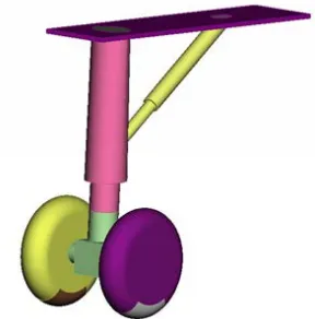
Initially, a typical simple landing gear system of Boeing 747 aircraft is modelled and meshed using ANSA software tool.
Fig. 1 Modelled landing gear system.
Fig. 2 Modelled landing gear - Mesh.
Fig. 3 Boundary condition.
4. Stress Analysis
In this paper the above modelled landing gear is analyzed for the following materials to find out the best material to suggest. Vertical load applied to the designed landing gear for all the cases is -1473950 N. This value is referred from Boeing 747 aircraft.
4.1 Aluminum Alloy 7075
Aluminum alloy 7075 is often used in the airspace industry, because it has a lightweight construction and a relative high tensile strength. It is so light and strong because the alloy has a high zinc and copper value. The alloy has a tensile strength of 540 MPa. The alloy melting temperature is 635°C. At low temperatures the material maintains its properties.
Density = 2.88 Kg/m3 Poisson’s ratio = 0.33 Yield strength = 95MPa Young’s modulus = 80GPa
Fig. 5 Aluminum Alloy 7075 – Deflection.
Table 1: Aluminum Alloy 7075 – Result
Maximum stress (MPa)
Maximum Deflection
(mm)
Factor of Safety
517.166 13.40 0.18
4.2 Alloys Steel 4340
Alloy 4340 is a low alloy steel with a high strength, toughness and good fatigue strength. The added materials are nickel, chromium and molybdenum. The alloy can easily be shaped at a high strength in the right form. The alloy has a tensile strength of 1863 MPa.. Alloy 4340 has a melting point of 1427°C and the properties will be retained when there is a low temperature.
Density = 7.7 Kg/m3 Poisson’s ratio = 0.33 Yield strength = 472.3MPa Young’s modulus = 200GPa
Fig. 6 Alloys Steel 4340 – Stress distribution.
Fig. 7 Alloys Steel 4340 - Deflection.
Table 2: Alloys Steel 4340 - Result
Maximum stress (MPa)
Maximum Deflection
(mm)
Factor of Safety
517.166 4.69 1.43
4.3 Titanium 6AL-4V
Ti-6Al-4V or Ti 6-4, is the most commonly used alloy. It is significantly stronger than commercially pure titanium while having the same stiffness and thermal properties (excluding thermal conductivity, which is about 60% lower in Grade 5 Ti than in CP Ti). Among its many advantages, it is heat treatable. This grade is an excellent combination of strength, corrosion resistance, weld and fabric ability.
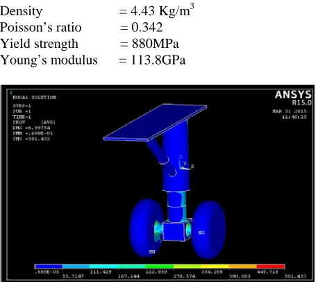
Density = 4.43 Kg/m3 Poisson’s ratio = 0.342 Yield strength = 880MPa Young’s modulus = 113.8GPa
Fig. 9 Titanium 6AL-4V - Deflection.
Table 3: Titanium 6AL-4V - Result
Maximum stress (MPa)
Maximum Deflection
(mm)
Factor of Safety
501.433 6.99 1.756
4.4 Titanium 6AL-6V-2Sn
Titanium 6Al 6V 2Sn is a heat treatable high strength alloy with lower toughness and ductility than Ti 6Al-4V. Generally, Ti-6Al-4V is used in applications up to 400 degrees Celsius. It has tensile strength of 1000 MPa.
Density = 4.54 Kg/m3 Poisson’s ratio = 0.30 Yield strength = 980MPa Young’s modulus = 110.3GPa
Fig. 10 Titanium 6AL-6V-2Sn – Stress distribution.
Fig. 11 Titanium 6AL-6V-2Sn - Deflection.
Table 4: Titanium 6AL-6V-2Sn - Result
Maximum stress (MPa)
Maximum Deflection
(mm)
Factor of Safety
448.982 5.326 2.18
4.5 Titanium 10Al-2Fe-3V
Titanium 10-2-3 (Ti 10-2-3) is used in the landing gear instead of steel. The main reason for this change is the reduction of 600 pounds in the aircraft, because the strength to weight ratio of titanium is higher than steel. The density is 4650kg/m3. Therefore Ti 10-2-3 is a high strength alloy and exists of titanium, aluminum, iron and vanadium. The Ti 10-2-3 has a tensile strength of 1170 MPa and yield strength of 1105 MPa. To ensure that material will not be damaged, the aircraft designers have to construct a landing gear were the forces will not exceed the maximum strength of 1105 MPa. For Ti 10-2-3 the melting point is 1649°C. Corrosion resistance of titanium is high.
Fig. 12 Titanium 10Al-2Fe-3V – Stress distribution.
Fig. 13 Titanium 10Al-2Fe-3V - Deflection.
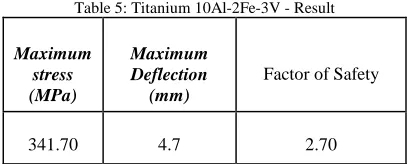
Table 5: Titanium 10Al-2Fe-3V - Result
Maximum stress (MPa)
Maximum Deflection
(mm)
Factor of Safety
341.70 4.7 2.70
6. Results and Discussion
Stress analysis plays very important role in finding structural safety and integrity of assemblies. The prior estimation of stress helps in finding suitable material and geometrical dimensions. Even optimization of dimensions are possible with stress estimates along with factor of safety calculations. Factor of safety indicates the safety margin of the designed structure which indicates how much the structure is overdesigned and how safe the components are. Here, we have the results of various material capability to bear the given load. It also includes displacement analysis.
Table 6: Result comparison
Material Maximum stress (MPa)
Maximum Deflection
(mm)
Factor of Safety
AA7075 517.166 13.40 0.18
AISI 4340 517.166 4.69 1.43
Ti 6Al-4V 501.433 6.99 1.756
Ti 6Al-6V-2Sn 448.98 5.326 2.18
Ti 10Al-2Fe-3V 341.70 4.69 2.70
7. Conclusion.
Initially, a typical landing gear of Boeing 747 aircraft is designed and meshed using ANSA software tool, and then analyzed for structural safety using ANSYS software. The maximum possible load (1473950N – 1/3 of Maximum landing load of Boeing 747) is given as design load. Landing gear is analyzed for the traditional metallic materials like Aluminum Alloy 7075, Alloys Steel 4340, Titanium 6AL-4V, Titanium 6AL-6V-2Sn, and Titanium 10Al-2Fe-3V. While comparing the results of the above mentioned materials, Titanium 10Al-2Fe-3V has the maximum factor of safety, and the minimum value of maximum stress developed and deflection. So, the modelled landing gear will be safer for the Titanium 10Al-2Fe-3V material to avoid the structural failure.
References
[1] M. Imran, S. A. R. M, M. Haneef, P. G. Student, M. Engineering, and G. College, “Static and Dynamic Response Analysis for Landing Gear of Test Air Crafts,” vol. 3, no. 5, 2014.
[2] P. Kabade and R. Lingannavar, “Design and analysis of landing gear lug attachment in an airframe,” vol. 2, no. 10, pp. 5358–5370, 2013.
[3] S. R. Basavaraddi, “Design and Analysis of Main Landing Gear Structure of a Transport Aircraft and Fatigue Life Estimation,” no. July, pp. 10–14, 2013.
[4] A. V Gaikwad, R. U. Sambhe, and P. S. Ghawade, “Modeling and Analysis of Aircraft Landing Gear : Experimental Approach,” vol. 2, no. 7, pp. 2–5, 2013. [5] K. Shahapurkar and R. B. G, “Stress Analysis of an
Aircraft Wing with a Landing Gear Opening Cutout of the Bottom Skin,” vol. 2, no. 5, pp. 406–412, 2014.
[6] T. Global and L. Gear, “Introduction to Landing Gear.” [7] “Stress analysis on main landing gear for small aircraft
تاداهجلإا ليلحت,” pp. 26–33, 2013.
[8] Praveen Joel P and Dr. Vijayan R, “Design and Stress Analysis of Nose Landing Gear Barrel (NLGB) of a typical naval trainer aircraft,” IOSR J. Mech. Civ. Eng., vol. 11, no. 2, pp. 67–74, 2014.
[9] A. Rajesh and B. T. Abhay, “Design and Analysis Aircraft Nose and Nose Landing Gear,” Int. J. Eng. Sci., pp. 2319– 1813, 2015.
[10] S. R. Basavaraddi, K. Manonmani, and P. M. Swami, “Stress and Fatigue Analysis of Landing Gear Axle of a,” pp. 224–228, 2015.
[11] M. Public, S. Performance, M. Civil, S. Performance, D. An, C. Service, H. Sector, and L. Government, “1 Introduction 1.1,” Framework, pp. 1–78, 1997.