R E S E A R C H
Open Access
Training design for precoded BICM-MIMO
systems in block-fading channels
Zohreh Andalibi
1,2*, Ha H Nguyen
1,2and Joseph E Salt
1,2Abstract
In order to improve bandwidth efficiency and error performance, a new training scheme is proposed for bit-interleaved-coded modulation in multiple-input multiple-output (BICM-MIMO) systems. Typically, in a block-fading channel, the training overhead used for obtaining channel knowledge is proportional to a power of 2 of the number of transmit antennas. However, this overhead can be reduced by embedding pilot symbols within data symbols before precoding. The values, positions, and the number of pilot symbols are found by minimizing the Cramer-Rao bound on the channel estimation error. Computer simulations are presented to demonstrate the advantage of the proposed scheme over other training methods, in terms of both the mean-square-error of the channel estimation and the system’s frame-error-rate.
Keywords:BICM-MIMO, block fading, channel estimation, training design, pilot symbols, Cramer-Rao bound, itera-tive receiver
1 Introduction
The pioneering work on multiple-input multiple-output (MIMO) systems [1] shows that a MIMO system can provide a multiplexing gain and accordingly high spec-tral efficiency over slow fading channels. On the other hand, to achieve a high diversity order, space-time trans-mission techniques can be implemented at the transmit-ter [2,3]. To achieve both high diversity order and coding gain in coded modulation systems, the concept of space-time transmission has also been applied [4,5]. In such systems, space-time transmission is typically implemented using a linear space-time matrix, or equivalently a linear precoder, so that a single modula-tion symbol is efficiently transmitted across multiple transmit antennas. Among many research works on pre-coder design for coded modulation systems with multi-ple antennas, the design that considers all the relevant components of the transmitter, namely precoding, mod-ulation, and interleaver, can be found in [5-7].
Specifi-cally, a full-rate precoder with any size and for any
number of transmit antennas is designed in [6] to maxi-mize the achievable diversity order and coding gain in MIMO block-fading channels.
It is shown in [6] that the maximum achievable diver-sity order can be realized by an iterative receiver that employs a soft-input soft-output detector [5] and under the assumption of having the perfectchannel state infor-mation (CSI) at the receiver. In practice, however, CSI has to be estimated using a channel estimator and it is never perfect. Two types of channel estimators have been used for MIMO block-fading channels in coded modulation systems, i.e., training-based and semi-blind channel estimators [8,9]. In both types of channel esti-mators, known signals are used to estimate the CSI at the first iteration of the iterative receiver.
Conventionally, for block-fading channels, known sig-nals or the training sequence is included at the begin-ning of each data block, which is called time-multiplexed training or pilot symbol-assisted modulation (PSAM) scheme [10]. This scheme however reduces bandwidth efficiency of MIMO systems, since the amount of training overhead needed is at least a power of 2 of the number of transmit antennas [11] to ensure the identifiability of the MIMO channel. A straightfor-ward application of the PSAM scheme to a BICM-MIMO system would be time-multiplex data informa-tion with the training informainforma-tion after the precoder.
As an alternative to the above conventional PSAM scheme, a potential benefit can be sought by
time-* Correspondence: [email protected]
1TRLabs, Saskatoon, Canada
Full list of author information is available at the end of the article
multiplexing data information with the training informa-tion beforethe precoder in the transmitter. This new approach shall reduce the required training overhead compared to the conventional PSAM, since the trans-mitted training symbols are spread over more time peri-ods; thanks to the precoder. This approach shall be referred to as precoded PSAM (PPSAM). Investigating power and time allocations of the training symbols in PPSAM scheme is the main objective of this article.
Moreover, by multiplexing the training sequence before precoder, training symbols can be exploited in both the initialization and iteration phases of the itera-tive channel estimation process. This is different from a conventional iterative channel estimator using PSAM scheme, in which training sequence is only used at the initialization phase. A natural question is whether the optimal training design for the initialization phase using PPSAM scheme is still optimal for subsequent iterations of an iterative channel estimator. On the one hand, the channel estimation error at the initialization phase translates to an SNR shift in the BER performance [8]. On the other hand, the channel estimation error from the last iteration of the iterative estimator has a strong impact on the error floor of the BER performance [12]. Therefore, optimal training sequence should be designed carefully that considers both initialization and iteration phases.
One of different criteria that have been used to design training sequences is the minimization of the Cramer-Rao bound (CRB) of the channel estimation error [10]. This criterion shall be used in this article due to two main reasons. First, it is directly related to the channel estimation error. Second, since the CRB is a lower bound on the mean-squared-error (MSE) of any unbiased estimator, designing training sequences using this criterion would be applicable to many estimation algorithms. Other design criteria, such as maximizing the channel capacity [8] and minimizing the outage probability [13], are based on some specific channel esti-mation algorithms.
The article is organized as follows. The system model of BICM-MIMO is presented in Section 2. In Section 3 a lower bound on the MSE of the channel estimator is obtained and the training sequence is designed by mini-mizing this bound. Section 4 provides numerical results and comparisons. Section 5 concludes the article.
2 System model
Figure 1 shows the block diagram of a BICM-MIMO system under consideration. At the transmitter, a chan-nel encoder with a rate-r error-correcting code converts the vector of information bitsbinto a codewordc. The coded bits are then interleaved by a random interleaver as described in [6] to produce the interleaved codeword
˜
c. The interleaved codewords are segmented into
groups of (Nnt- Np) ×mbits, where Nis the spreading
factor of the precoder, ntis the number of transmit
antennas,Npis the number of pilot symbols inNnt
pre-coded symbols and mis the number of bits carried by
one symbol of a QAM constellation whose size is |Ω| =
2m. Next, the coded bits are mapped to (Nnt - Np)
QAM constellation points. In this step,Npknown pilot
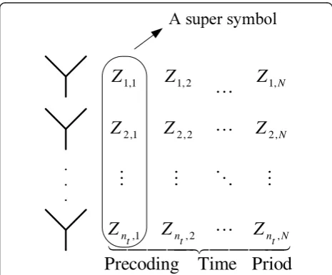
symbols are inserted in every segmented group of (Nnt -Np) data symbols to produceN super-symbols. Here,
each super-symbol refers to a group of nt consecutive
symbols. Investigating the positions and the number of pilot symbols (i.e., Np) to be used in eachNntsymbols is the main objective of this article.
Every group ofNsuper-symbols is then spread overN
time periods using a linear precoder G. TheNnt×Nnt
matrix G multiplies a vector of Nnt QAM symbols at
the precoder input, and generates Nntsymbols to be
transmitted overntantennas, overNtime periods.
This is illustrated in Figure 2. Let
xk= [x(k−1)Nnt+1, x(k−1)Nnt+2, . . ., x(k−1)Nnt+Nnt] be the
kth vector to be precoded. Then,xkGgives the precoded
symbols. Here, xi’s are complex data or pilot symbols
belonging to the 2m-QAM constellationΩ. It is assumed that the data symbolsxi’s are i.i.d with varianceσx2. After
precoding, precoded symbols are transmitted throughnt
transmit antennas over a block-fading channel.
Withnttransmit antennas and nr receive antennas,
the channel is modeled by an nt ×nr matrix. For
fre-quency-flat Rayleigh fading, coefficients of the channel matrix are i.i.d. zero-mean circularly symmetric complex Gaussian random variables with variance σ2
h. The chan-nel is assumed to be block fading withncdifferent
chan-nel realizations during each codeword. For the kth
symbol to be precoded, xk, the Nnt× Nnr extended
channel matrix,Hk, can be written as
Hk= diag
⎧ ⎪ ⎨ ⎪
⎩H
[1] k ,. . .,H
[1] k ,
N/ns
H[2]k ,. . .,H[2]k ,. . .,H[ns]k ,. . .,H[ns]k ⎫ ⎪ ⎬ ⎪
⎭, (1)
wherensis the number of distinct channel realizations
during Ntime periods of each codeword. To simplify
the notation it is also assumed(a) thatnsdivides N. For
example, if the length of a codeword is 64 andnc = 32,
then choosing N = 2 would make ns = 1, whereas
choosingN= 4 givesns= 2. Notation H[kt] refers to the nt × nr complex matrixk that defines the tth channel
realization included in ns channel realizations. The
extended channel input/output relationship is expressed by
where yk= [y(k−1)Nnr+1, y(k−1)Nnr+2, . . ., y(k−1)Nnr+Nnr]
is the received vector at the kth precoding time
per-iod and wk is the noise vector with size 1 × Nnr
whose components are i.i.d zero-mean circularly
symmetric Gaussian random variables with variance N0. It is noted from (2) that although both data and pilot symbols are precoded, the part of the precoder that multiplies the pilot symbols depends on the
posi-tions of the pilot symbols in xk. Equivalently, the
design of the pilot symbols is governed by the proper-ties of the precoder used. Since this study adopts the transmission framework and precoder design in [6], it is useful to review the properties of the precoder pro-posed in [6].
In general, the properties of the precoder in [6] are established by the maximum-likelihood decoding analy-sis and an assumption of ideal channel interleaving. Spe-cifically, this linear precoder which achieves full diversity order and maximum coding gain satisfies the following two conditions:
•A genie condition, which guarantees orthogonal
and equal norm sub-rows in the linear precoding
matrix. Each sub-row has size nt in a precoding
matrix with sizeNnt× Nnt.
•Dispersive nucleo algebraic (DNA) condition, which is based on Proposition 2 in [6], forces null and orthogonal nucleotides with sizes’=N/ns. Nucleo-tides refer to subparts of sub-rows with sizes’.
Channel
Figure 1Block diagram of a BICM-MIMO system with a linear precoder and proposed training insertion.
4
Figure 2Spreading a precoded symbol overntantennas andN time periods-denoted byZk= [Z1,k, Z2,k, . . ., Zn
t,k]
A linear precoder that satisfies the above two sets of conditions is called DNA-cyclo precoder and has the best performance in terms of achieving diversity and
coding gains with low complexity receiver whenN≤nt.
It is suggested in [6] that to generate one class of such a precoder, aNs’× Ns’ cyclotomic rotator, denoted byF, that satisfies the genie condition is first selected. Then
the orthogonal nucleotides are placed inside an Nnt×
Nntmatrix and they are separated with null nucleotides. Therefore, the DNA-cyclo precoder matrix can be expressed by subparts of a cyclotomic rotator as follows:
G=
and⊗denotes the Kronecker product.
The properties that shall be useful for the problem considered in this article, which are implied directly
from the genie and DNA conditions, are FFH =INs ‘
and [i] [t]([j] [t])H= 1
Nδ(i−j). It is also useful to point
out that each component ofF has an exponential form
with a scaling factor of √1
N s.
The iterative receiver is also shown in Figure 1. The channel estimator produces an estimate of the channel using the minimum MSE (MMSE) criterion based on the training sequence. Details about channel estimation with the proposed method of inserting training sequence shall be given in Section 3. After channel estimation is performed using the training signal, the input soft-output demodulator uses the MMSE criterion to demo-dulate the data. The soft-output MMSE demodulator computes the extrinsic information for the interleaved bits, {(˜cl)
ext}, from the received symbols. To obtain Λ
-values, the demodulator exploits the a priori
informa-tion of the coded bits coming from the decoder, {(˜cl)
ap}, and the channel estimate Hˆk. In the first iteration, the
demodulator assumes that the a priori Λ-values are
zero, except for the pilot symbols. For the corresponding bits of the pilot symbols, the demodulator uses a large
number, say ±100 as their a prioriΛ-values. The
de-interleaved outputs, i.e., {(cl)
ap}, become thea priori Λ -values used in the channel decoder shown in Figure 1 after removing the information of pilot symbols. The
channel decoder uses the maximum a posteriori
prob-ability (MAP) algorithm to compute the extrinsic Λ
-values {(cl)
ext}. for all coded bits, which are used again in the next iteration in the demodulator. In subsequent
iterations, soft information from the decoder is used to improve the performance of the channel estimator. The detailed operation of the iterative channel estimator is discussed in the following sections.
3 Training design and channel estimator
As discussed before, the criterion used for training design in this article is the CRB on the channel estima-tion error. The bound states that the MSE of any unbiased estimator is lower bounded by the trace of inverse of complex Fisher information matrix (FIM) [14]. To derive FIM, the relation between the channel input and channel output during one block-length, i.e.,
N/nstime periods, whose corresponding channel matrix
is H[kt], is of interest. In the following, index k is omitted, since it suffices to consider the transmission of a single precoded symbol for the purpose of channel estimation. With the previously described structure of the precoder, the channel output during one super-sym-bol time is given by
y[i,t]= received symbol duringNtime periods, with sizenr× 1. Moreover, h[t]is the column vector formed by vertically
stacking the columns of annt ×nrchannel realization
matrix H[t]and x[τ]’s are constructed by splittingx in Ns’ sub-vectors with size 1 ×nt/s’. In the following, we call these sub-vectorsx[τ]’snucleosymbols.
It is quite obvious from (4) that, to have all the received super-symbols,y[i,t], contain training informa-tion, there should be at least one pilot nucleo (i.e.,nt/s’
pilot symbols) in each group of Ns’ nucleos to be
precoded.
With the above structure of the proposed training
sequence, the number of pilot symbols in Nnt
trans-mitted symbols would be Np = np × nt/s’, where np
nucleo symbols in a symbol to be precoded are assigned to training sequence. Therefore, (4) can be rewritten as
y[i,t]= Ns’}, that are assigned to data and pilot nucleos, respec-tively, and |Id|+|Ip|= (N s−np) +np=N s. Note that the subscripts “d” and “p” are used to differentiate between data and pilot nucleos. For convenience, the notations [pi,t] [τ] and [di,t] [τ]are used to refer to sub-rows of Fthat are multiplied by pilot and data nucloes,
i.e., x[pτ] and x [τ]
following the notation T[i,t] is used for
The derivation of FIM is given in the next section. Pilot symbols are exploited at the initialization phase and in subsequent iterations considering the special structure of the training sequence. In general, training design can be investigated for these two phases sepa-rately. However, for the precoder adopted in this article, the optimal training design obtained for the initialization phase turns out to also be optimal for the iteration phase. Nevertheless, the optimal numbers of pilot nucleos in these two phases of channel estimation are not the same.
3.1 Fisher information matrix
The key steps in deriving the FIM in the initialization phaseare now given. Without loss of generality we drop superscript tin (5) and perform all the derivations for the first block period (i.e., t = 1). Collecting all the observations during the first block period of length s’in
a vector, the FIM for the channel estimation problem
at the initialization phase is defined and computed as
FIMinit(n
FIM on those parameters of interest. Using the i.i.d. assumption on noise and data,p(|h) can be approxi-mated as a complex normal distribution with mean
μ= [μT The i.i.d. assumptions on noise and data make the
FIM additive. Specifically,
FIMinit(np, xp, Ip) =
s
i=1FIM init
i . The quantity FIM
init i
is obtained as follows:
FIMinit
element!# of 1 at position
l−1 nt
$
+ 1,(l−1 modnt)+ 1 "
. The derivative of the
third term in (8) is
Using all the above equations and after some manipu-lations, one has overs’quantities FIMiniti , the total FIM is given by,
FIMinit(n
For designing training sequence, (10) can be simplified further using numerical calculation. Using numerical calculation, it is observed that for a Rayleigh-distributed channel, the matrix Eh{R−i1} in (10) is approximately a diagonal matrix(b), αInr. This observation means thatEh
Eh
Moreover, using the property of the Kronecker pro-duct (A ⊗B)(C ⊗D) = (AC) ⊗(BD), it follows that
Therefore (10) can be further simplified to
FIMinit(n
In general, the second term in (11) depends on Ip,
but not on the training symbols, whereas the first term
depends on both xp and Ip. Although both terms
depend onnp, how FIMinitdepends onnpis determined
by Ip. Therefore, in the following Ip and xp are first optimized. Thennpis determined for the optimized Ip.
For the iteration phase, specifically the last iteration, estimation and detection are implemented using infor-mation about the data symbols as well as the pilot sym-bols. Thus, the parameter of interest in deriving FIM is
θ = [hTxd]T. Moreover,
manipulations, the FIM for channel estimation in the iteration phase is given by
FIMiter(n
3.2 Optimization of training symbols and their positions This section is first concerned with minimizing the CRB expression for the initialization phase. The minimization is under a constraint on the power budget for the train-ing sequence. Such a constraint is expressed as
Using the properties of the precoder employed in this study, the above constraint can be simplified to
s N
%
τ∈Ipxp[τ](x[pτ]) H
≤Pt. The other obvious constraint is that the training symbols should be selected from QAM constellationΩ. Then, the training symbols,xp’s and their positions, specified by Ip, are obtained by sol-ving the following constrained optimization problem:
min nucleo and the FIM is given in (11).
To proceed, lets consider two separate cases for
pro-blem (14): np = 1 andnp ≥ 2. Case 1 (np= 1): In this
case the FIM is simplified to
Inr⊗
Because of the shift-invariant property of (15) with respect to τ, τ can be any value in the set {1, 2, . . . , Ns’}. For simplicity, set τ = 1 and the superscript τ is omitted. Using the fact that ifX>0 then tr (X-1)≥ ∑i1/ (X)i,i, the original optimization problem is simplified by minimizing the lower bound of the objective function.
On the other hand, %si=1
constraint is s Nxpx not hard to see that the solution of the simplified
opti-mization problem is
|(xp)1|2= |(xp)2|2=· · ·= |(xp)nt/s|
2= NPt
nt . It means
that all pilot symbols should have the same power. For example, one can select corner points of the QAM con-stellations for the training symbols.
Case 2 (np ≥ 2): In this case there are two options
for the placements of pilot nucleos. The first option is to group all pilot nucleos in one single cluster and the second option is to spread pilot nucleos. It can be shown that the CRB is invariant with respect to a shift of the placements of pilot nucleos in both options. Therefore, it suffices to select one cluster or one spread placement. However, the precoder has been designed such that the soft-output demodulator works with uncorrelated inputs and putting pilot nucleos between data nucleos may violate this condition. That condition is satisfied when A[i] has a diagonal form. The implication of this property is to place pilot
nucloes equi-spaced in xk and
and i0 Î {1, . . . ,n}, which leads to A[i]=σx2Ns−np
Ns Is. In this selection it is supposed that np is divisible by Ns’.
Then the FIM in (11) can be represented by
Inr⊗
To obtain the above expression of the objective func-tion, the following property has been used:
s
Moreover, the only term that depends on the training
symbols is %τ∈Ip(xp[τ])Hx[pτ] in (16). Finally, using the constraint on training power, which can be written as
s
the solution is given by
%
τ|(x[pτ])j|2=NPntt; j= 1,. . .,nt/s.
Now consider the training design for the iteration phase. Observe that all the terms in (12) have diagonal
forms with equal diagonal elements, except
%
means that the solution of problem (14), but with
FIMinit(np, xp, Ip) replaced by FIMiter(np, xp, Ip), is to choose equal diagonal elements for this term. There-fore, the training sequence designed for the initialization is also optimal for the iteration phase.
In summary, by selecting pilot nucleos such that the sum of the powers of their corresponding pilot symbols with the same indexes are equal, the bound on CRB is minimized. The above condition can give different selec-tions for pilot symbols from a two-dimensional constel-lation. It should be pointed out, however, that not all selections guarantee that pilot symbols belong to stan-dard QAM constellations.
3.3 Determination of the number of the training symbols For block-fading channels, the number of pilot nucleos, i.e., np, should be as small as possible that meets the
power constraint. Using a larger value for np wastes
bandwidth and does not change the system
performance.
The optimum numbers of the training symbols in the initialization phase and iteration phase are not the same. This is explained as follows. At the initialization, by looking at (7), it is observed that the first term in (11) is
an increasing function of np. However, the second term
is a decreasing function of np that is multiplied bynr.
Therefore,npthat minimizes the CRB are determined
by the summation of these two terms, which is also
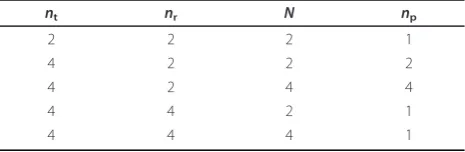
determined by the value of nr. Table 1 gives several
examples of optimalnpfor different sets ofnt,nrand N. For the iteration phase, the expression in (12) means that the CRB in the iteration phase always increases by increasingnp. Since it is assumed that there is perfect information about the data symbols in the iteration phase, which is not the case in reality, it is most appro-priate to select np considering only the initialization phase.
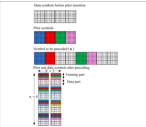
To demonstrate the optimal training design, Figure 3 shows a graphical structure for a simple example, where Pt = 4σx2,np= 2,N= 2,nt= 4 andnr= 2. In this exam-ple,ns = 1. Then the size of pilot nucleos should bent/ s’= 2, wheres’=N/ns= 2.
3.4 Channel estimation
For the channel estimation task, one can view the
received vector during one block length as
ϕ[t]= [(y[1,t])T, (y[2,t])T, . . ., (y[s,t])T]T.
At the initialization, the mean and covariance matrix of this vector are given in Section 3.1. By treating the data symbols as nuisance parameters, the MMSE chan-nel estimate can be found as [14]
ˆ
h[t]=σh2TH(σh2TTH+Rϕ[t])ϕ[t] (19)
whereT= [(T1)T, . . . , (T[s’])T]T.
In the subsequent iterations, soft information from the decoder is used to improve the performance of the channel estimator. The channel estimator uses such information to compute new estimates of the channel coefficients using expected values of the data symbols. Therefore, the interleaved {(cl)
ext} from the decoder are fed back to the estimator to calculate the expected values of the data symbols, i.e.,E{xd}. The entries of E {xd} are calculated using {(˜cl)
ap} at each iteration by E {(xd)i} = ∑xÎΩx ·p((xd)i =x). The detailed derivations of the probabilityp((xd)i=x) fromΛ-values are given in
Table 1 Optimumnpfor several sets of parameters {nt,
[15] (note that the calculation depends on the mapping rule inΩ).
To verify the results obtained in this section, Section 4 compares numerically the MSE performance of the above channel estimator obtained with the optimal and suboptimal training sequences.
4 Illustrative results
In this section, the frame-error-rate (FER) and MSE per-formances of BICM-MIMO systems using a MMSE iterative channel estimator are presented. The space-time precoder is the DNA-cyclo precoder that satisfies the properties outlined in Section 2. We consider quad-rature phase-shift keying (QPSK) modulation with Gray mapping.
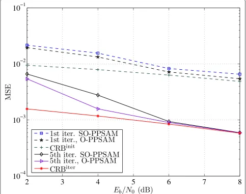
The MSE performance of a BICM-MIMO for a
codeword length of 4×1024 bits is shown for a 4× 2
block-fading MIMO channel in Figure 4, when nc = 2.
In this figure, Eb is the energy per information bit.
The code used is the 16-state convolutional code with generator polynomials (23, 35) in octal form. In Fig-ure 4, the MSE curves are obtained after 1 and 5 iterations of the iterative channel estimation/demodu-lation/decoding, with the following cyclotomic rotator [16]:
= 1 2
⎡ ⎢ ⎢ ⎣
1 1 ej6π/15 −ej6π/15 ej2π/15 jej2π/15 −ej8π/15 jej8π/15
ej4π/15 −ej4π/15 ej10π/15 ej10π/15
ej6π/15−jej6π/15−ej12π/15−jej12π/15
⎤ ⎥ ⎥ ⎦
Data symbols before pilot insertion
Pilot symbols
Symbol to be precoded
Pilot and data symbols after precoding
Training part
Data part
2
N
4
t
n
)
(
x
and when the setting forN, ns, npandPtin Figure 3
are used. The channel is generated randomly and is assumed to be Rayleigh distributed. For the purpose of comparison, the results for MSE performances of the optimal PPSAM, denoted by O-PPSAM and the subop-timal PPSAM, denoted by SO-PPSAM as well as the CRB are shown in Figure 4. For SO-PPSAM, two pilot nucleos are inserted as one cluster in front of data nucleos in a symbol to be precoded. In contrast, in the case of O-PPSAM, the optimized training sequence embeds the pilot nucleos at the first and third positions
ofNs’= 4 positions for nucleos. The MSE curves show
that the performance of the optimal scheme is better than the sub-optimum scheme for the first iteration (i.e., initialization). In fact the MSE performance of the pro-posed scheme closely approaches the CRB at highEb/N0
after 5 iterations.
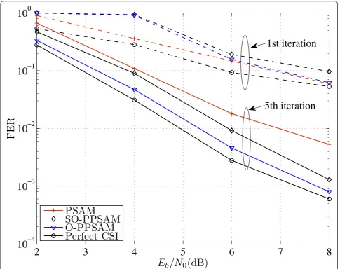
In Figure 5, the FER performance of the system with the PPSAM schemes is compared with the conventional PSAM training scheme for the same system parameters as in Figure 4. The top curve is the FER performance of the system with the conventional PSAM training scheme. Note that for a fair comparison, the training scheme in PSAM also meets the training power con-straint as trace (XpXHp) =Pt, where Xp is the training matrix placed at the beginning of each block of the pre-coded symbols. The optimal option for PSAM scheme in terms of minimizing the FER as proposed in [11] is
to select Xp to have orthogonal columns. The simplest
option is )2×σ2 x/ntInt =
)
σ2
xInt, which results in the
same power budget as that of the proposed scheme. As can be seen from Figure 5, the O-PPSAM scheme offers 0.5 dB performance gain as compared to the
SO-2
3
4
5
6
7
8
10
−410
−310
−210
−1E
b/N
0(dB)
MS
E
1st iter. SO-PPSAM
1st iter., O-PPSAM
CRB
init5th iter. SO-PPSAM
5th iter., O-PPSAM
CRB
iterPPSAM scheme at FER = 10-2. In comparison with PSAM, the performance of the PSAM scheme is about 0.5-1.5 dB worse than the proposed scheme depending onEb/N0 after 5 iterations. This is expected because the
pilot information is embedded in the precoded symbols for the proposed scheme and not for the PSAM scheme. In this way, the demodulator can also make use of this information. Note, however, that for the first iteration, since there is no information about data, PSAM works the best. More importantly, while the proposed scheme uses a little bandwidth for training information (for the system considered in this figure the training overhead is np× nt/s’ = 4), the training overhead of PSAM scheme isnt× nt= 16, which is quadruple. To investigate the effect of the number of transmit antennas, two different
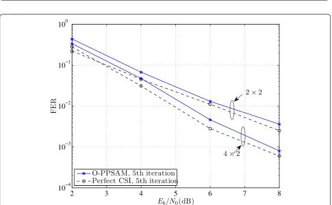
systems, one with 2 × 2 channel and one with 4 × 2
MIMO channel, are compared in Figures 6 and 7 in
terms of MSE and FER, respectively. For both channels,
np= 2 and the optimum scheme are used whenN= 2,
while other system parameters are the same as those used for Figure 4. As can be seen from Figure 6, the MSE of the channel estimation increases when increas-ing the number of transmit antennas. This is expected because there are more channels to be estimated for the same amount of training information and power as done in the comparison. Nevertheless, the gain in diver-sity by using more antennas can still improve the overall FER performance as seen in Figure 7.
5 Conclusion
In this article, a new training design for a BICM-MIMO system over a block-fading channel has been proposed. The design inserts pilot symbols into the data symbols before precoding. The new training sequence improves
2
3
4
5
6
7
8
10
−410
−310
−210
−110
0E
b/N
0(dB)
FE
R
PSAM
SO-PPSAM
O-PPSAM
Perfect CSI
1st iteration
5th iteration
Figure 5Comparison of FER performance obtained with the optimal PPSAM, sub-optimal PPSAM and PSAM scheme-over a 4×2 block-fading channel withnc= 2, whenN= 2 andnp= 2 after 1 and 5 iterations of iterative channel-estimation/demodulation/
2
3
4
5
6
7
8
10
−410
−310
−2E
b/N
0(dB)
MS
E
Simulation, 5th iteration
CRB
4
×
2
2
×
2
Figure 6Comparison of MSE performance obtained with the optimal PPSAM for 2×2 and 4×2 block-fading channels withnc= 2, whenN= 2 andnp= 2 after 5 iterations of iterative channel-estimation/demodulation/decoding.
2
3
4
5
6
7
8
10
−410
−310
−210
−110
0E
b/N
0(dB)
FE
R
O-PPSAM, 5th iteration
Perfect CSI, 5th iteration
2
×
2
4
×
2
bandwidth efficiency as compared to the conventional PSAM scheme and can also be used by the demodulator in the receiver. In order to design the optimal training symbols and their positions, the CRB on the channel estimations at the initialization and at the iteration phases are minimized. Compared to PSAM, perfor-mance improvement achieved with the proposed train-ing is about 1.5 dB at a FER level of 10-2.
Endnotes
a
In practice, sincensis typically an approximated value over some range and sinceNcan be selected, such an assump-tion can be fulfilled.bUsing the matrix inversion lemma, one has R−1
i = (HA[i]HH+N0Inr)−
1=N−1 0Inr+N−
2
0HA[i]HH(Inr+N−
1
0 HA[i]HH)−1.
Therefore, for high SNR, E{R−i1} can be approximated by N−01Inr.
Author details
1TRLabs, Saskatoon, Canada2Department of Electrical and Computer
Engineering, University of Saskatchewan 57 Campus Drive, Saskatoon, SK S7N5A9, Canada
Competing interests
Zohreh Andalibi has received funding from TRLabs of Saskatchewan. This organization partially is financing this manuscript.
Received: 7 August 2011 Accepted: 4 March 2012 Published: 4 March 2012
References
1. G Caire, S Shamai, On the achievable throughput of a multiantenna Gaussian broadcast channel. IEEE Trans Inf Theory.49(7), 1691–1706 (2003). doi:10.1109/TIT.2003.813523
2. SM Alamouti, A simple transmit diversity technique for wireless communications. IEEE J Sel Areas Commun.16(8), 1451–1458 (1998). doi:10.1109/49.730453
3. V Tarokh, N Seshadri, AR Calderbank, Space-time codes for high data rate wireless communication: performance criterion and code construction. IEEE Trans Inf Theory.44(2), 744–765 (1998). doi:10.1109/18.661517
4. J Boutros, E Viterbo, Signal space diversity: a power and bandwidth eficient diversity technique for the Rayleigh fading channel. IEEE Trans Inf Theory.
44(4), 1453–1467 (1998). doi:10.1109/18.681321
5. J Boutros, N Gresset, L Brunel, Turbo coding and decoding for multiple antenna channels, inInternational Symposium on Turbo Codes and Related Topics, Brest, France, pp. 1–8 (2003)
6. N Gresset, L Brunel, J Boutros, Space-time coding techniques with bit-interleaved coded modulations for MIMO block-fading channels. IEEE Trans Inf Theory.54(5), 2156–2178 (2008)
7. N Gresset, JJ Boutros, L Brunel, Optimal linear precoding for BICM over MIMO channels, ISIT, 66, Chicago, IL, (September 2004)
8. M Coldrey, P Bohlin, Training-based MIMO systems, Part I: performance comparison. IEEE Trans Signal Process.55(11), 5464–5476 (2007) 9. M Nicoli, S Ferrara, U Spagnolini, Soft-iterative channel estimation: methods
and performance analysis. IEEE Trans Signal Process.55(6), 2993–3006 (2007)
10. M Dong, L Tong, BM Sadler, Optimal insertion of pilot symbols for transmissions over time-varying flat fading channels. IEEE Trans Signal Process.52(5), 1403–1418 (2004). doi:10.1109/TSP.2004.826182 11. G Taricco, E Biglieri, Space-time decoding with imperfect channel
estimation. IEEE Trans Wirel Commun.4(4), 1874–1888 (2005)
12. Y Huang, JA Ritcey, Joint iterative channel estimation and decoding for bit-interleaved coded modulation over correlated fading channels. IEEE Trans Wirel Commun.4(5), 2549–2558 (2005)
13. P Piantanida, SM Sadough, On the outage capacity of a practical decoder accounting for channel estimation inaccuracies. IEEE Trans Commun.57(5), 1341–1350 (2009)
14. SM Kay,Fundamentals of Statistical Signal Processing: Estimation Theory, (Prentice-Hall PTR, New Jersey, 1993)
15. MA Khalighi, JJ Boutros, Semi-blind channel estimation using the EM algorithm in iterative MIMO APP detectors. IEEE Trans Wirel Commun.5(11), 3165–3173 (2006)
16. GM Kraidy, P Rossi, Full-diversity iterative MMSE receivers with space-time precoders over block-fading MIMO channels, inProc IEEE Int Conf Wireless Commun and Signal Processing, Suzhou, pp. 1–5 (2010)
doi:10.1186/1687-1499-2012-80
Cite this article as:Andalibiet al.:Training design for precoded BICM-MIMO systems in block-fading channels.EURASIP Journal on Wireless Communications and Networking20122012:80.
Submit your manuscript to a
journal and benefi t from:
7Convenient online submission
7Rigorous peer review
7Immediate publication on acceptance
7Open access: articles freely available online
7High visibility within the fi eld
7Retaining the copyright to your article