R E S E A R C H
Open Access
Hardware and software design of BMW
system for multi-floor localization
Mu Zhou
1,2, Bin Wang
1*, Zengshan Tian
1and Liangbo Xie
1Abstract
Although the Micro Electro Mechanical System (MEMS) sensors are capable of providing short-term high positioning accuracy, every positioning result significantly depends on the historical ones, which inevitably leads to the long-term error accumulation. The Bluetooth Low Energy (BLE) is independent of the accumulative error, but the positioning accuracy is suffered by the irregular jump error resulted from the Received Signal Strength Indicator (RSSI) jitter. Considering the requirement of accurate, seamless, and consecutive positioning by the existing commercial systems, we propose a new integrated BLE and MEMS Wireless (BMW) system for multi-floor positioning. In concrete terms, first of all, the way of fingerprint database construction with the reduced workload is introduced. Second, the fingerprint database is denoised by the process of affinity propagation clustering, outlier detection, and RSSI filtering. Third, the robust M estimation-based extended Kalman filter is applied to estimate the two-dimensional coordinates of the target on each floor. Finally, the barometer data are used to calculate the height of the target. The extensive experimental results show that the proposed system can not only restrain the accumulative error caused by the MEMS sensors but also eliminate the irregular jump error from the BLE RSSI jitter. In an actual multi-floor environment, the proposed system is verified to be able to achieve the Root Mean Square (RMS) positioning error within 1 m.
Keywords: Multi-floor positioning, Data fusion, Robust M estimation, BLE, MEMS
1 Introduction
At present, the indoor positioning has broad application such as searching the cars and elevators in underground parking lot and pushing advertisements or discounts to the customers in large shopping malls. The Global Navi-gation Satellite System (GNSS) [1–3] well meets the pre-cision requirement of outdoor positioning, but in indoor environment, its performance may drastically deterio-rate due to the serious signal blocking and multipath effect. In response to this compelling problem, a batch of researchers put forward a variety of indoor position-ing systems based on the Bluetooth Low Energy (BLE) [4], Ultra Wideband (UWB) [5], Radio Frequency Iden-tification (RFID) [6], Micro Electro Mechanical System (MEMS) sensors [7], and Wireless Local Area Network (WLAN) [8, 9].
*Correspondence: [email protected]
1Chongqing Key Lab of Mobile Communications Technology, Chongqing University of Posts and Telecommunications, Chongqing 400065, China Full list of author information is available at the end of the article
The hardware cost, range limitation, and long-term error accumulation limit the development of the con-ventional positioning systems. Among them, the MEMS sensors can be used to perform the Pedestrian Dead Reckoning (PDR) [7, 10] by using the inertia and heading information though it contains the accumulative error. The BLE Received Signal Strength Indicator (RSSI)-based positioning system can meet the requirement of low power, low cost, and no accumulative error though the RSSI jitter caused by multipath effect may seriously decrease the positioning accuracy.
In recent decade, various integrated systems have been significantly concerned to improve positioning accuracy [11, 12]. The systems [13–15] using Kalman and parti-cle filter to achieve the WLAN/MEMS fusion positioning reduce the accumulative error of MEMS sensors, but they fail to constrain the WLAN RSSI jitter. To solve the RSSI jitter problem, the authors in [16] build the observation equation of the RSSI according to the signal propagation model, which is difficult to be constructed in the complex indoor environment. In [17], the authors design an indoor positioning system by fusing the WLAN and Magnetic
Angular Rate and Gravity (MARG) data to solve the prob-lems of RSSI jitter and accumulative error. However, this system cannot achieve the three-dimensional positioning, which is significantly required by the current commercial applications.
This paper presents a new integrated BMW system for multi-floor positioning. First of all, the fingerprint database is optimized by using the affine propagation clus-tering, outlier detection, and RSSI filtering algorithms. Specifically, the fingerprint denoising is performed to reduce the probability of large errors of BLE positioning, and then, the gait detection approach is used to estimate the walking speed and heading angle of the target based on the extended Kalman filter (EKF). Second, the robust EKF is designed to restrain the accumulative error caused by the MEMS sensors, as well as eliminate the irregular jump error from the BLE RSSI jitter. Finally, according to the barometer data and geographical location informa-tion, the height of the target is calculated to achieve the multi-floor positioning.
2 Related work
In this section, we will briefly introduce some related work in three aspects of fast fingerprint database construction, fusion positioning, and multi-floor positioning and also address the corresponding limitations.
Fast fingerprint database construction Although the fingerprint positioning has been studied for a long time, it still cannot be applied widely since its offline phase generally spends a huge amount of time on finger-print database construction. By using the conventional approaches, the target area is calibrated with a batch of equally spaced grids, and then, the fingerprints are col-lected at the grids point-by-point [18, 19]. The involved time cost rises significantly with the increase of environ-mental size, which hinders the development of fingerprint positioning. In [20], the authors propose to construct an incomplete fingerprint database with realistic cover-age gaps, and meanwhile study the performance of sev-eral interpolation and extrapolation approaches used for recovering the missing fingerprints. In [21], according to the distribution of Reference Points (RPs) with respect to each Wi-Fi Access Point (AP), the signal propagation model is constructed as a function of spatial structure, which can be used to construct the fingerprint database quickly.
Fusion positioning At present, the common single posi-tioning systems are difficult to adapt to the complex indoor environment. In response to this compelling prob-lem, a variety of fusion positioning systems are designed to compensate for the shortcomings of each single one. In [22], the data fusion from both the proprioceptive and
exteroceptive sensors, like the odometer, Global Position-ing System (GPS), Light Detection and RangPosition-ing (LIDAR), and vision, as well as the knowledge of road map is con-sidered to perform the fusion positioning. In [23], the authors conduct data fusion by integrating the RSSI and Time difference of Arrival (TDOA) measurements to esti-mate the superior locations of the target. Specifically, by employing the nonparametric estimation approach, which is robust to the variations of measurement noise and quantization, it is addressed that the fusion position-ing is more robust and higher accurate and has lower implementation cost.
Multi-floor positioning The mainstream of indoor posi-tioning systems mainly focuses on the horizontal coor-dinate estimation, whereas little research has been done on the vertical coordinate estimation. In [24], the authors propose a WiFi-based indoor positioning system that takes both the characteristics of trilateration and scene analysis into account. The authors in [25] rely on the path loss model to construct a light fingerprint radio map to find the target floor. However, these systems are applied to only determine the floor on which the target is most probably located, but they cannot estimate the accurate locations of the target.
3 System description
3.1 System framework
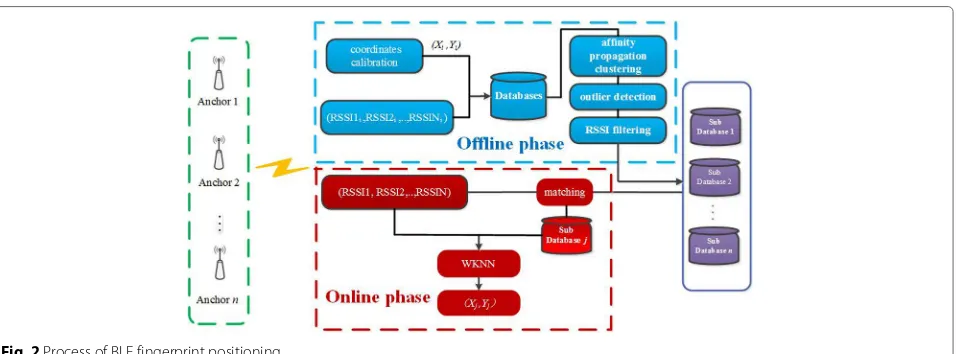
As shown in Fig. 1, our system contains four modules, BLE fingerprint positioning module, speed and heading calculation module, EKF module, and height calculation module. According to the output of accelerometer, gyro-scope, and magnetometer, the gait detection and quater-nion calculation are carried out to estimate the walking speed and heading angle of the target, which will be sent to the PDR to perform localization. Then, the localiza-tion results by the PDR and Weighted K Nearest Neighbor (WKNN) are selected as the input of the EKF to obtain the two-dimensional coordinates of the target. After that, based on the output of barometer, two-dimensional posi-tioning result, and geographical location information, the height of the target is inferred.
3.2 BLE fingerprint positioning
Fig. 1Framework of BLE/MEMS fusion positioning system
3.2.1 Fast fingerprint database construction
The data in the conventional fingerprint database are col-lected point-by-point, which limits the application of fin-gerprint positioning due to the requirement of huge time cost. In response to this compelling problem, we propose a new fast fingerprint database construction approach. First of all, the floor plan of the target environment is imported into the terminal as a map. Second, the map is repre-sented by a batch of straight lines (labeled with dash blue lines) with the starting and ending points (labeled with red triangles), as shown in Fig. 3.
Supposing that the pixel size of the map is mmapx by mmapyand the actual size of the target environment isMx
byMy, we can obtain the relations of the pixels and actual
locations in (1).
Xi=xmapi∗mMmapx +X0
Yi=ymapi∗mMmapy +Y0
(1)
where(X0,Y0)is the actual origin location, which is rep-resented by(0, 0)in the map.(xmapi,ymapi)and(Xi,Yi)are
the coordinates of theith point in the map (with the length
mmapxand widthmmapy) and actual environment (with the
lengthMxand widthMy) respectively.
Fig. 3Floor plan imported into the terminal
We construct the standard fingerprint database by
Xi=X0+Lstep_x∗ii∈1,· · ·,|XLend−step_Xx0| Yj=Y0+Lstep_y∗jj∈1,· · ·,|YLend−step_Yy0|
(2)
whereLstep_xandLstep_yare the physical intervals in theX
andYdirections, respectively, in the actual environment, which are normally set asLstep_x=Lstep_y.
By taking the walking path from(x0,y0)to (xend,yend) (in Fig. 3) as an example, a volunteer starts walking after labeling (x0,y0) on the screen of the terminal and then labels (xend,yend) on the screen of the terminal when he/she stops walking. During the walk,(xi,yi)is notated
as theith location, which is calculated by
⎧
where vn and θn are the walking speed and heading. εxi = vivsin(θi)isin(θi)(Lsin(1) − Lpdrsin(2)) and εyi =
vicos(θi)
vicos(θi)(Lcos(1) −Lpdrcos(2)) are the error com-pensation in the X andY directions respectively.Land
Lpdr = N i=1
viare the actual distance and the estimated one
by the PDR from the starting to ending locations.1is the heading of(xend,yend)relative to(x0,y0).2is the heading of(xN,yN)relative to(x0,y0).
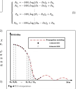
Since the RSSI in standard fingerprint database may be lost when the walking speed is too fast, we propose to rely on the interpolation approach to estimate the lost RSSI by propagation modeling, as shown in Fig. 4.
We use the propagation model below to describe the relations of the RSSI and distance from each anchor to the terminal.
Pd= −10Ntlogd+Pd0 (4)
wherePd0is the RSSI with 1-m distance from the anchor.
d is the distance from the anchor to terminal.Nt is the
path loss exponent.
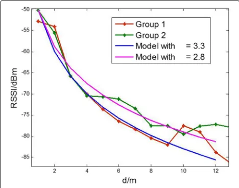
Figure 5 shows two groups of test points indicating the variation of RSSI with respect to the distance from an anchor to the terminal. As can be seen from Fig. 6, the constructed propagation model matches the variation of RSSI well when the distance is within 10 m.
We randomly selectNm terminal locations to train the
path loss exponent for each anchor by
⎧
Fig. 5Variation of RSSI with respect to the distance
where the notation “•2” represents the 2-norm opera-tion.D0is the anchor location.Diis theith location of the
terminal.Pdiis the RSSI atDi. We calculateN =
We rely on the affinity propagation clustering [26] to classify the off-line RSSI data and then construct each cluster as a sub-database, as shown in Table 1. In online phase, we match the newly collected RSSI data to the cluster center of each sub-database and then select the sub-database with the best matching to perform posi-tioning. To achieve this goal, we define density(x,k)and relative_density(x,k) as the density and relative density
Fig. 6Result of propagation modeling
Table 1Pseudo-code of sub-database construction
Algorithm:Sub-database construction
Data:Raw fingerprint database Result:sub-databases
1cluster←AP_Cluster(input); 2foreachclusteri∈clustersdo 3 foreachpointj∈clusterido
4 ifrelative_densitypointj >Threshold
5 Outliers are reassigned to the nearest neighbor; 6 backto Step 1;
7 end 8 end
9 Obtain the cluster center; 10end
11 Construct each cluster as a sub-database;
[27] of the newly collected RSSI xwith respect to its k
nearest neighbors respectively. pseudo-code of sub-database construction is shown in Table 1.
clusteriis theith cluster. pointjis thejth point. Thresh-oldis the threshold of relative density.
3.3 Speed and heading estimation
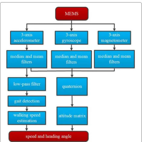
We integrate the data from the axis accelerometer, 3-axis gyroscope, and 3-3-axis magnetometer to estimate the walking speed and heading of the target (Fig. 7). First of all, the median and mean filters are fused to eliminate the device noise. Second, the low-pass filtering is per-formed on the output of 3-axis accelerometer to detect the gait and consequently estimate the walking speed. Finally, the data from the 3-axis accelerometer, 3-axis gyroscope, and 3-axis magnetometer are combined with the posture matrix [28] to estimate the heading.
3.3.1 Speed estimation
We calculate the step size of the kth step by Pk = CSk4
Anormmax−Anormmin, where the maximum and
Fig. 7Process of speed and heading estimation
The parameter CSk is trained by using the Back
Propa-gation (BP) neural network [29, 30]. Specifically, the step frequencyFSkand heightHSkare selected as the input and
CSk is selected as the output to train the coefficientsVij
andWj. The number of neurons on hidden layer is 11, as
shown in Fig. 8.
With the pedestrian walking, the output of accelerom-eter Anorm =
zb generally changes in sinusoid mode [28], whereaxb, ayb, and azb are the out-put of accelerometer inX,Y, andZdirections respectively. A step is detected whenAnormreaches a local maximum higher than a given threshold A0. By setting the sam-pling frequency asfsand number of samples between two
Fig. 8Structure of BP neural network
adjacent maximum as N, the time duration of the kth step istk= fNs and the corresponding estimated speed is
vk =
We define the carrier and geographic reference coordi-nate systems asx-y-zand ENU, whereE,N, andU axes point to the geographic east, north, and sky directions, respectively, as shown in Fig. 9.
The coordinate transformation from the carrier to geo-graphic reference coordinate systems is described as
⎡ coordinates of the target in the carrier and geographic ref-erence coordinate systems respectively. According to the relations of the posture matrix and quaternion [31], we have
Using the rigid body angular differential equation, we obtain
tion quaternion.wx,wy, andwzare the angular velocities
inX,Y, andZdirections in the carrier coordinate system. The notation “⊗” represents the quaternion multiplica-tion, which is also used in [31]. We rewrite the formula above in matrix form as
dq
We discretize the formula above as
is the initial quaternion.m is the index of samples. We normalize the quaternion as
The posture matrix can be updated based on the quater-nion obtained in (12). However, the quaterquater-nion may not be accurate due to the error of the gyroscope. To solve this problem, we construct the quaternion equations of status and observation as follows.
status.Wmis the process noise.Vm+1is the observation noise. The observation variableYm+1is calculated by
Ym+1=
are the output of accelerometer and mag-netometer, respectively, in the carrier coordinate system.
g =0 0 1T is the normalized output of accelerometer
when the target is static in the geographic reference coordinate system.L=0 by bz
T
is the output of mag-netometer in the geographic reference coordinate system, in whichby=
Finally, the heading of the target is estimated by
ϕ=arctan
We choose the geographic east and north directions, walk-ing speed, and headwalk-ing to construct the equation of status below. graphic east and north directions, respectively, at moment
t − 1. vt−1 and ϕt−1 are the walking speed and head-ing, respectively, in the geographic reference coordinate system at moment t − 1. Wt−1 is the Gaussian white
mation variables,δij is the Kronecker function, andQis
The output of BLE fingerprint positioning and the esti-mated speed and heading are selected as the observation variable to construct the equation of observation below.
Zt=h(Xt,Vt) the geographic east and north directions by the BLE fin-gerprint positioning at moment t. vmemst and ϕtmems are the estimated speed and heading, respectively, by using the MEMS sensors at momentt.Vtis the Gaussian white
noise with zero mean at moment t. EV(i)VT(j) = R(i,j)δij, i,j = 1,· · ·,n, in which n is the number of
observation variables and R(R > 0) is the covariance matrix of observation noise.
3.4.2 Robustness enhancement
Considering that the change of the weighting factors of the IGG3 [32] is slight, we first define the IGG3 weight function below to enhance the robustness of the EKF. We first define the IGG3 weight function below.
¯
wherepiandp¯iare theith diagonal elements in the weight
matrixP= R−1and equivalence weight matrixP¯ respec-tively.k0 ∈ [1, 1.5] andk1 ∈ [2.5, 3] are the weights. The normalized residual vectoruiis calculated by
ui= vi σvi
(23)
whereviis theith element in then×1-dimensional
resid-ual vector of observationV.σvi= √σq0vi, in whichqviis the reciprocal ofviandσ0is the variance factor [32].
Then, we apply the M estimation approach to enhance the robustness of the EKF. The main difference between the conventional EKF and robust one is the updating of filter gain, as shown below.
¯
K(t)=P(t,t−1)HT(t)×
H(t)P(t,t−1)HT(t)+ ¯R(t)−1 (24)
whereK¯(t)is the filter gain at momentt.P(t,t−1)is the one-step prediction of the matrix of error covariance at momentt.H(t)is the matrix of observation at momentt.
¯
R(t)= ¯B−t1is the covariance matrix of observation noise, in whichB¯tis the equivalent weight matrix.
3.5 Height estimation 3.6 Pressure measure
The principle of barometric pressure measure is that the atmospheric pressure in the gravitational field decreases as the height increases [33]. Thus, the altitude of the target can be estimated by using the barometric pressure mea-sured by the barometer. When the height of gravity, H, is less than 11 km, the standard pressure formula can be described as
wherePsis the pressure value.
Finally, the height of the target is estimated by
h= R×H
R−H (26)
whereR=6356766 m is the radius of earth. SinceRH, we can obtainR−RH ≈1 andh≈H.
3.7 Algorithm design
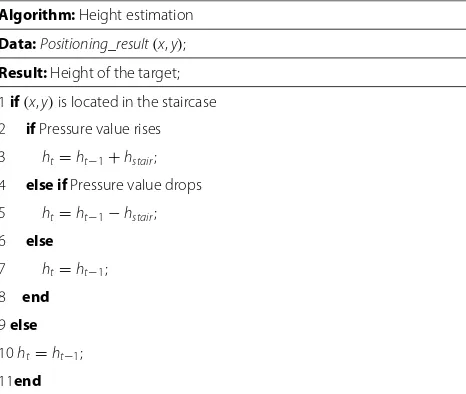
The walking pattern in indoor environment can be sim-ply divided into walking flat, upstairs, and downstairs. In our system, we rely on the output of barometer to deter-mine the walking pattern of the target and then count the number of steps to estimate the height of the target, as shown in Table 2. In this table,ht−1 andhstair stand for the height of the target at momenttand step height respectively.
3.8 System implementation
Figure 10 shows the schematic diagram of the proposed system. The BLE anchor broadcasts the packets in a real-time manner. A smartphone equipped with the BLE and MEMS modules is selected as the target. Both the BLE
Table 2Pseudo-code of height estimation
Algorithm:Height estimation
Data:Positioning_result(x,y); Result:Height of the target;
Fig. 10Schematic diagram of the proposed system
Fig. 11Interface of positioning server
Fig. 13Hardware configuration
Fig. 14Interface of Android Studio software
Fig. 16Interface of database management
Fig. 17Floor plan of the lower floor
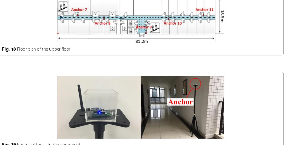
Fig. 18Floor plan of the upper floor
Fig. 20Display on terminal side
and MEMS data are packaged and transmitted to the positioning server through the 4G network, and then, the estimated locations of the target are displayed by the server, as shown in Fig. 11.
3.8.1 Hardware platform
The CC2540 chip of Texas Instruments (TI) is selected as the BLE anchor with the broadcast frequency 10 Hz and power 0 dBm, as shown in Fig. 12.
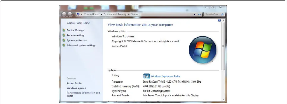
The target is installed with the Android 6.0 operating system and designed to support the BLE, accelerometer, magnetometer, and barometer modules. The positioning and web servers are based on the Windows 7 operating system with the processor of Intel (R) Core (TM) i3-416 CPU @ 3.60 GHz, as shown in Fig. 13.
3.8.2 Software platform
The APP used to collect the data from the BLE and MEMS sensors as well as access the positioning server is devel-oped by Android Studio software, and the corresponding algorithms are written on the Eclipse software platform in JAVA (Figs. 14 and 15). The MySQL database and Apache Web server are selected to save the positioning result and show them through the PHP and JavaScript (Fig. 16).
4 Experimental results
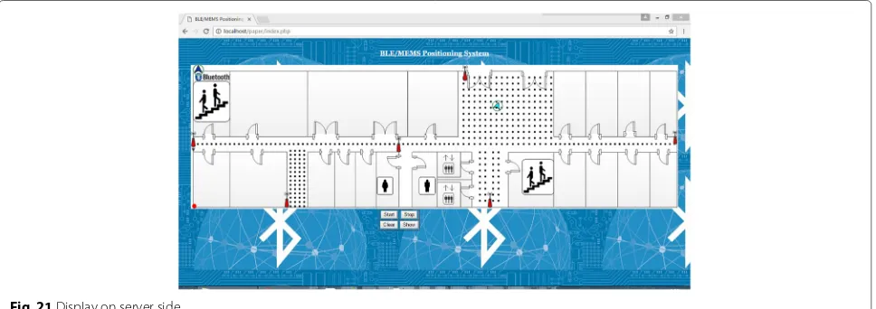
Two adjacent floors in a building are selected as the exper-imental environment, as shown in Figs. 17 and 18. There are 11 BLE anchors, namely Anchor 1,· · ·, 11, fixed in tar-get environment and the 514 RPs (marked with bullet) are uniformly calibrated with the interval of 0.6 m. Figure 19 shows some photos of the actual environment. The posi-tioning result can be displayed on both the terminal and server sides, as shown in Figs. 20 and 21.
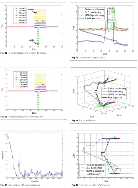
Figures 22 and 23 show the result of fingerprints cluster-ing without and with denoiscluster-ing. The process of denoiscluster-ing increases the probability of merging the physically adja-cent RPs into the same cluster.
Although the irregular jump error of BLE positioning may exceed 10 m, the ultimate error by fusion positioning will converge into a small value as the time going on. By taking the result in Fig. 24 as an example, the error of ini-tial positioning is over 13 m, but the one almost decreases to less than 2 m when the timestamp is over 100 s.
We continue to compare the performance of the pro-posed and conventional positioning algorithms by using the MEMS or BLE solely. Figure 25 shows the result of locations tracking by different algorithms on a floor. The real trajectory starts from point A, along Anchor 3 and Anchor 6, along Anchor 4 and Anchor 3, and back to point A (see Fig. 25).
The result of locations tracking on two different floors is also shown in Fig. 26. In this test, the real trajectory is
Fig. 22Fingerprints clustering without denoising
Fig. 23Fingerprints clustering with denoising
Fig. 24Error variation of fusion positioning
Fig. 25Locations tracking on a floor
Fig. 26Results in 3D view
Fig. 28CDF of positioning errors
selected from point A, along Anchor 3 and point B, going upstairs to point C, along Anchor 8 and Anchor 7, and ending at point D (see Figs. 26 and 27).
As can be seen from Fig. 26, the large accumulative error of MEMS positioning exists, while the BLE positioning is suffered by the irregular jump error and cannot be accu-rate enough when the target is located in the staircase. In contrast, the proposed fusion positioning algorithm can restrain the accumulative error of MEMS position-ing as well as eliminate the irregular jump error of BLE positioning. In addition, it is also verified that the pro-posed algorithm is featured with good height resolution, which makes the system more robust to the actual indoor multi-floor positioning.
Figures 27 and 28 show the Cumulative Density Func-tion (CDF) of errors and the error at each test point respectively. From these figures, we can find that the posi-tioning errors by using the BLE or MEMS solely are much larger than the one of the proposed fusion positioning. In addition, different percentile errors of fusion, BLE, and MEMS positioning are also illustrated in Table 3.
Figure 29 shows the height error of each test point when the target is located in the staircase. From this figure, we can find that our system is capable of achieving bet-ter height resolution compared to the conventional ones using the MEMS or BLE solely.
Table 3Different percentile values with respect to the positioning error
Percentile Fusion BLE MEMS values (%) positioning (m) positioning (m) positioning (m)
50 <0.60 <3.80 <2.29 70 <0.77 <4.48 <3.37 90 <1.03 <5.26 <8.41
Fig. 29Positioning error at each test point
Finally, we investigate the stability of our system under the long-term testing. To achieve this goal, three shapes (square, linear, and irregular shapes) of trajectories are considered in Figs. 30, 31, 32, 33, 34, 35, and 36 respec-tively. Obviously, our system exhibits the best perfor-mance in terms of accumulative error constraint, irregular jump error elimination, and height resolution under dif-ferent shapes of trajectories.
5 Conclusions
In this paper, both the hardware and software of BMW system are designed and implemented for indoor multi-floor positioning. Based on the extensive experimental results, it is demonstrated that the proposed system is capable of solving the problems of accumulative error constraint and irregular jump error elimination in MEMS
Fig. 31Locations tracking undersquare shapeof trajectory
Fig. 32CDF of positioning errors undersquare shapeof trajectory
Fig. 33Locations tracking underlinear shapeof trajectory
Fig. 34CDF of positioning errors underlinear shapeof trajectory
Fig. 35Locations tracking underirregular shapeof trajectory
and BLE positioning respectively. In general, our system is featured with high positioning accuracy, good height resolution, and strong long-term stability.
Acknowledgements
This work was supported in part by the Program for Changjiang Scholars and Innovative Research Team in University (IRT1299), Special Fund of Chongqing Key Laboratory (CSTC), Fundamental and Frontier Research Project of Chongqing (cstc2017jcyjAX0380, cstc2015jcyjBX0065, cstc2015jcyjBX0085), and University Outstanding Achievement Transformation Project of Chongqing (KJZH17117).
Authors’ contributions
The authors have contributed jointly to all parts on the preparation of this manuscript, and all authors read and approved the final manuscript.
Competing interests
The authors declare that they have no competing interests.
Publisher’s Note
Springer Nature remains neutral with regard to jurisdictional claims in published maps and institutional affiliations.
Author details
1Chongqing Key Lab of Mobile Communications Technology, Chongqing
University of Posts and Telecommunications, Chongqing 400065, China. 2Tianjin Key Laboratory of Wireless Mobile Communications and Power
Transmission, Tianjin Normal University, Tianjin 300387, China.
Received: 26 May 2017 Accepted: 2 August 2017
References
1. M Jia, L Wang, Q Guo, X Gu, W Xiang, A low complexity detection algorithm for fixed up-link scma system in mission critical scenario. IEEE Internet Things J.PP(99), 1–1 (2017)
2. M Jia, X Gu, Q Guo, W Xiang, N Zhang, Broadband hybrid
satellite-terrestrial communication systems based on cognitive radio towards 5g. IEEE Wirel. Commun.23(6), 96–106 (2016)
3. M Jia, L Wang, Z Yin, Q Guo, X Gu, A novel spread slotted aloha based on cognitive radio for satellite communications system. EURASIP J. Wirel. Commun. Netw.2016(1), 232 (2016)
4. ES Lohan, J Talvitie, PFE Silva, inInternational Conference on Localization and GNSS. Received signal strength models for WLAN and BLE-based indoor positioning in multi-floor buildings (IEEE, Gothenburg, 2015), pp. 1–6
5. K Yu, JP Montillet, A Rabbachin, UWB location and tracking for wireless embedded networks. Signal Process.86(9), 2153–2171 (2006)
6. YL Lai, J Cheng, A cloud-storage RFID location tracking system. IEEE Trans. Magn.50(7), 1–4 (2014)
7. L Zhang, J Liu, H Jiang, Senstrack: energy-efficient location tracking with smartphone sensors. IEEE Sensors J.13(10), 3775–3784 (2013) 8. N Alsindi, Z Chaloupka, N Alkhanbashi, An empirical evaluation of a
probabilistic RF signature for WLAN location fingerprinting. IEEE Trans. Wirel. Commun.13(6), 3257–3268 (2014)
9. M Zhou, F Qiu, K Xu, Z Tian, Semi-supervised learning for indoor hybrid fingerprint database calibration with low effort. Comput. Commun.86(C), 57–74 (2016)
10. B Koo, S Lee, M Lee, inInternational Conference on Indoor Positioning and Indoor Navigation. PDR/fingerprinting fusion indoor location tracking using RSS recovery and clustering (IEEE, Busan, 2015), pp. 699–704 11. M Tanenhaus, D Carhoun, T Geis, inIEEE/ION Position Location and
Navigation Symposium. Miniature IMU/INS with optimally fused low drift MEMS gyro and accelerometers for applications in GPS-denied environments (IEEE, South Carolina, 2012), pp. 259–264
12. K Kloch, P Lukowicz, C Fischer, inInternational Symposium on Wearable Computers. Collaborative PDR localisation with mobile phones (IEEE, San Francisco, 2011), pp. 37–40
13. W Xiao, W Ni, KT Yue, inInternational Conference on Indoor Positioning and Indoor Navigation. Integrated Wi-Fi fingerprinting and inertial sensing for indoor positioning (IEEE, Guimaraes, 2011), pp. 1–6
14. H Wang, H Lenz, A Szabo, inPositioning, Navigation and Communication, 2007. Wpnc ’07. Workshop On. WLAN-based pedestrian tracking using particle filters and low-cost MEMS sensors (IEEE, Hannover, 2007), pp. 1–7 15. M Atia, M Korenberg, A Noureldin, inIEEE International Symposium on
Mechatronics and Its Applications. A WiFi-aided reduced inertial sensors-based navigation system with fast embedded implementation of particle filtering (IEEE, Sharjah, 2012), pp. 1–5
16. V Malyavej, W Kumkeaw, M Aorpimai, inInternational Conference on Electrical Engineering/Electrinics, Computer, Telecommunications and Information Technology. Indoor robot localization by RSSI/IMU sensor fusion (IEEE, Krabi, 2013), pp. 1–6
17. X Liu, Z Wu, X Lin, WLAN/MARG/GPS integrated positioning system based on a self-adaptive weighted algorithm. Qinghua Daxue Xuebao/J. Tsinghua University.53(7), 955–960 (2013)
18. M Zhou, Q Zhang, Y Wang, Hotspot ranking based indoor mapping and mobility analysis using crowdsourced Wi-Fi signal. IEEE Access.5, 3594–3602 (2017)
19. M Zhou, Y Tang, Z Tian, Semi-supervised learning for indoor hybrid fingerprint database calibration with low effort. IEEE Access.5, 4388–4400 (2017)
20. J Talvitie, M Renfors, ES Lohan, Distance-based interpolation and extrapolation methods for RSS-based localization with indoor wireless signals. IEEE Trans. Veh. Technol.64(4), 1340–1353 (2015)
21. SS Jan, SJ Yeh, YW Liu, Received signal strength database interpolation by kriging for a Wi-Fi indoor positioning system. Sensors.15(9), 21377–21393 (2015)
22. J Laneurit, C Blanc, R Chapuis, IEEE, Columbus, inIntelligent Vehicles Symposium. Multisensorial data fusion for global vehicle and obstacles absolute positioning, (2003), pp. 138–143
23. M Mcguire, KN Plataniotis, AN Venetsanopoulos, Data fusion of power and time measurements for mobile terminal location. IEEE Trans. Mob. Comput.4(2), 142–153 (2005)
24. HH Liu, YN Yang, inTENCON 2011 - 2011 IEEE Region 10 Conference. WiFi-based indoor positioning for multi-floor environment (IEEE, Cebu, 2012), pp. 597–601
25. IH Alshami, NA Ahmad, S Sahibuddin, inMalaysian Software Engineering Conference. A light WLAN radio map for floor detection in multi-floor environment localization (IEEE, Seri Kembangan, 2015), pp. 135–139 26. X Wang, L Yang, L Wang, inIEEE International Conference on Mobile Ad-Hoc
and Sensor Networks. Improved AP clustering algorithm based on target segmentation (IEEE, Dalian, 2013), pp. 539–541
27. IR King, Density data and emission measure for a model of the coma cluster. Astrophys. J.174(174), 123 (1972)
28. K Zhao, B Li, A Dempster, inIEEE International Conference on Wireless Communication and Sensor Network. A new approach of real time step length estimation for waist mounted PDR system (IEEE, Changsha, 2015), pp. 400–406
29. Y Zhang, L Wu, Stock market prediction of S&P 500 via combination of improved BCO approach and BP neural network. Expert Syst. Appl.36(5), 8849–8854 (2009)
30. S Jia, Q Qiu, J Li, inIEEE International Conference on Information and Automation. BP neural network based localization for a front-wheel drive and differential steering mobile robot (IEEE, Lijiang, 2015), pp. 2270–2274 31. Y Yang, W Gao, X Zhang, Robust Kalman filtering with constraints: a case
study for integrated navigation. J. Geodesy.84(6), 373–381 (2010) 32. S Zhao, S Chan, inIEEE International Symposium on Circuits and Systems. A
novel algorithm for mobile station location estimation with none line of sight error using robust least m-estimation (IEEE, Seattle, 2008), pp. 1176–1179