R E S E A R C H
Open Access
Joint network-channel code optimization for
wireless sensor networks
Nabih Alaoui, Vahid Meghdadi and Jean-Pierre Cances
*Abstract
Optimization of sensor network architecture in order to improve the overall system performance at the end processing station is an important challenge. A lot of architectures have been designed to optimize the bit error rate. Conventionally, this optimization is done by inserting relays between sensors and destination. These relays insert redundant information by mixing the incoming streams from sensor nodes, hence creating parity check information which is very useful to help decode the transmit information from sensors. The goal is to combine network and channel coding to match network on graph to code on graph, and this is called adaptive network coded cooperation (ANCC). Compared to the previous works in the field, we propose a new transmit protocol based on the use of beamforming technique which is very efficient in terms of throughput and is fully compatible with the physical network coding (PNC) principles. Furthermore, we propose a distributed coding scheme where the relay, the destination, and the sensors are all equipped with repeat accumulate (RA) channel code structures. The relay has a special RA structure to suit the need of the PNC multiple access channel.
Keywords:Wireless sensor networks; Physical network coding (PNC); Precoding; Repeat accumulate (RA) code structure
1 Introduction
Different protocols and architectures have been designed to improve the performance of sensor networks. The use of network coding has appeared recently as a promising way to help find an answer to this problem [1-5]. In net-work coding, some intermediate nodes mix the messages they received and forward this obtained mixture to several destinations simultaneously [6-8]. When compared to time sharing-based schemes where destinations are served sequentially, network coding improves considerably the throughput efficiency [9]. Among the different network coding techniques for wireless sensor networks, one promising approach is the use of joint network-channel coding (JNCC). The basic principle consists in the use of relays which decode incoming streams and combine them to obtain additional redundant information. The redun-dant information from the relays is combined at the des-tination node with the original information from the sensors to obtain an equivalent powerful block code such as a LDPC one. Hence, the goal of this kind of architecture
is to couple networks on graphs with codes on graph. This was first proposed in [10] and further developed in [11,12] with some optimization of the coding scheme at the relay place. The transmission protocol can be summarized in the following way. In a first time slot, each source node broadcasts its information to both relays and destination. In a second time slot, the relays then decode the received packets and combine them by XOR operation to obtain parity check bits which are transmitted to the destination. The second task clearly corresponds to the network cod-ing step and contains some challengcod-ing aspects. The main ones are of course the choice of the source incoming mes-sages in the XOR operations and the degree of each XOR operation (the number of incoming streams which are combined). Finally, at the destination node, a graph code such as low-density parity check (LDPC) or low-density generator matrix (LDGM) codes is built and decoded using belief propagation (BP) algorithm.
Compared to the existing literature and particularly to [12], we propose, in this paper, new attractive features to further improve the performance of suck kind of sys-tems. The first point concerns the improvement of the broadcast transmit phase. In [12], the authors propose
* Correspondence:[email protected]
Xlim, Department C2S2, UMR CNRS 7252, University of Limoges, Limoges 87068, France
to use orthogonal channels to make the transmissions from sources to relays error free. This is quite penalizing in terms of bandwidth or throughput efficiency depend-ing on the used multiple access technique (FDMA or TDMA). In this paper, supposing that the relay and the destination are equipped withKantennas, we propose a new transmission protocol which enables 2.K uplink and downlink transmissions to be accomplished within (K+ 2) time slots. This outstanding performance is obtained because we found a way to handle the co-channel inter-ference at the relay place. The idea behind this comes from the concept of interference alignment [13] and consists in making the two messages delivered to and from the same sensor fall in the same direction at the relay. We propose precoding and beamforming tech-niques [14-18] to ensure that the signals delivered to and from the same sensor can be paired together. An-other merit of our proposed system is that we consider two-way message exchanges between the destination and the sensors. We consider explicitly the case where the destination node sends back information controls toward the sensor nodes and this is not studied in [12].
Furthermore, since our proposed scheme is fully com-patible with the physical network coding (PNC) princi-ples, we propose a distributed coding scheme where channel coding is applied at the destination and at the sensors level and network coding is applied at the relay to encode the incoming mixed streams from the destin-ation and the sensors. We show that our proposed sys-tem enables to transmit simultaneously the K encoded messages from the sensors and the control encoded messages from the destination. Thanks to the precoding matrices, these messages are combined at the relay in such a way that we have K streams to be network encoded at the relay place. We suppose that the end nodes (destination and sensors) are all equipped with repeat accumulate (RA) codes, and we show how to de-sign the channel decoder at the relay which channel-decodes the superimposed channel-coded packets to obtain the soft version of the arithmetic summation of the source packets and transforms the superimposed source packets to the network coded packets. These processing tasks at the relay have been detailed in [19,20] and the authors have named them: channel-decoding-network-coding process (CNC). Similar con-struction rules can be found in [21,22]. The decoder at the relay uses a special repeat accumulate (RA) code structure to accommodate the obtained particular in-coming streams with precoding.
The rest of the paper is organized as follows. In the second part (Section 2), the system model and the new proposed transmit protocol are described. In the third part (Section 3), the network coding scheme is detailed and we put the em-phasis on the design of the decoder at the relay. In the
fourth part (Section 4), we present the results of the simu-lation. Finally, concluding remarks are given in Section 5.
The following notations are used: (.)T, (.)H, and Ef gð Þ: denote transpose, conjugate transpose, and expectation of (.), respectively.
2 System model
We consider a real wireless sensor network with K sen-sors, each sensor is equipped with one transmit/receive antenna and with a channel encoder/decoder. In this paper, we will use RA code structure for the coding of in-coming streams from the sensors. No direct link between sensor and destination exists. The relay is equipped with Q multiple antennas and with K network-channel de-coder/encoders. The destination node is equipped with N≥K multiple antennas too and containsK channel en-coders/decoders. We will suppose classically thatN≥Q≥ K, i.e., the destination node has the best capability while some relays are more capable than the elementary sensors. The cooperation phases in such a system are decomposed into two main ones.
The first one is the broadcast phase where sensors and destination exchange their information with the help of the relay. We suppose that there is no direct available link between the sensors and the
destination source.
The second one is the network coding phase at the relay. After decoding, the relay combines the incoming streams and retransmits them to the destination and sensor nodes. The way the relay operates the network coding tasks is described in the next section.
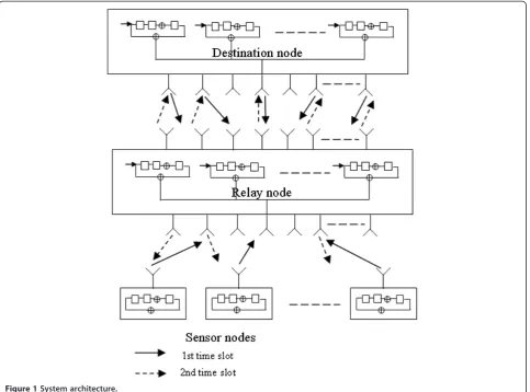
In this part, we put the emphasis on the transmit pro-tocols. In [12], the authors assume that the sensors transmit their data in orthogonal channels (typically se-quentially in the case of TDMA). This results in bad throughput efficiency. We propose a new transmit protocol which enables 2.Kuplink and downlink trans-missions to be accomplished within (K+ 2) time slots (Figure 1).
2.1 Transmit protocols
yR¼HDRPmþ XK
j¼1
HjRsjþnR; ð1Þ
where HDR is the Q×N channel matrix between the destination node and the relay,HjRis theQ× 1 channel vector between the relay and the jth sensor andnR de-notes theQ× 1 additive white Gaussian noise vector.
During the second time slot, the relay decodes the re-ceived signal to obtain soft information about the quan-tities: mj⊕sj, using a particular decoding algorithm. Denoting uj^ the estimated value formj⊕sjat the end of the decoding process, uj^ is then encoded by a standard
RA coder. Vectors ^t ¼ ^t1;^t2;…;^tK
T
, which represent the encoded words corresponding to ^u1;u^2;…;uK^ , are
then broadcast, after being BPSK modulated, to the sensor nodes and to the destination node in different time slots. Denoting~t the modulated vector corresponding to~t, the vectors ~t are transmitted during the next K time slot to the sensors using precoders W(j). Supposing that we
intend to transmit thejth element of vector~t to sensorj, we can useW(j)defined by:
In other words, matrix W(j) is built with the super-position of an all zero matrix of size K×K except for thejth term on the diagonal which is equal to 1 and an all zero matrix of size (Q-K) ×K. Physically, this corre-sponds to the case where the components of ~t are transmitted sequentially over the first K transmit an-tennas at the relay. We obtain the received signal at the jth sensor as:
yj¼HR jWð Þj~tþnj; ð2Þ
where HRj is the 1 ×Q channel vector between the jth sensor and the relay. Supposing that the uplink and downlink channels are reciprocal, we have HR j¼HHjR. Of course, during this phase, the destination does not take into account the received data.
After this phase, i.e., after the first (K+ 2) time slots, vectors ~t are transmitted to the destination source within the next time slot. To do this, we addQ-Kzeros at the end of ~t to obtain a new transmit vector of size Q× 1, named~t. The relay uses a precoding vectorF of size Q×Q and the destination source weights the re-ceived signal with a vector G of size Q×N. Physically, this means that theKdata information are transmitted by selectingKantennas among a set ofQantennas. We obtain the received signal of sizeQ× 1 at the destination node as:
yD ¼GHRDF~t′þGnD: ð3Þ
One possible choice for G and F consists in:
F¼ HH RDHRD
−1
and¼HH
RD. Once again, we suppose that:
HRD¼HHDR.
2.2 Precoding matrix design at the destination source for the first time slot
Apart from the already cited constraint power, we have to be sure that each sensor should not receive informa-tion for other sensor. The proposed design is based on the concept of interference alignment [23] and consists in grouping the messages from and to the same sensor, i.e.,miandsi together. This is facilitated by defining the precoding matrixPat the destination as follows:
P¼pffiffiffiαHH
DR HDRHHDR
−1
HR; ð4Þ
where HR= [H1R, H2R, …, HKR] and α is a factor which ensures that the transmission power at the destination
node is normalized. By using such a precoding matrix P, the relay can group the messages from and to the same user as follows:
yR¼HR ffiffiffi
α
p
mþs
þnR; ð5Þ
where s= [s1, …, sK]T. In this case, similar to physical layer network coding (PNC) [4], the relay directly broad-casts the mixture ofmands. Concerning the total trans-mission power at the destination with the use of precoding matrixP, we have
EtracePPH
¼α:E trace HHDR HDRHHDR
−1
HR HHDR HDRHHDR
−1
HR
H
¼α:E trace HDRHHDR
−1H
RHHR
h i :
ð6Þ
Using the conditionEtracePPH≤N and choosing¼
N=E trace HDRHHDR
−1
HRHHR
h i
, we ensure, provided
that E trace HDRHHDR
−1
HRHHR
h i
is bounded, that the transmission power at the base station is normalized. The
proof thatE trace HDRHHDR
−1H
RHHR
h i
is bounded can
be found in [15] or [24].
3 Network coding at the relay
The coding principle is directly related to the received signal at the relay (see Equation (5)), we have
yR¼HR ffiffiffi
α
p
mþs
þnR:
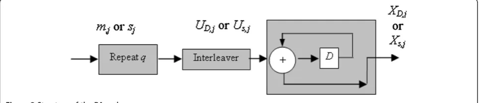
We suppose now that the transmitted messages from the elementary sensors and from the destination are both encoded with a RA code structure [19,20]. The structure of the RA code is drawn on Figure 2.
As mentioned in [19,20], there are two classical solu-tions to address the problem of cooperative network coding at the relay (CNC). The first one consists in de-coding mi and si from yRseparately. The relay can first decode mi while regarding the other message si as
interference, and can then decode si after removing the decoded information mi from the decoded signal. Combining the soft outputs of the decoderPmi,si(a,b) = Pr(mi=a,si=b/yR)Pmi,si(a,b) = Pr(mi=a,si=b/yR), we can generate: mi⊕si. The second solution consists in esti-mating PXs;j⊕XD;jð Þ ¼a Pr Xs;j⊕XD;j¼a=yR
from the re-ceived vectoryRwith for example the method in [25]. By decoding the estimate ofXs,j⊕XD,ji.e.:PXs;j⊕XD;jwith a soft input decoder, the relay can obtain:mi⊕si.
3.1 The proposed decoding scheme
It is possible to design a decoding scheme with higher per-formances compared to the two above-mentioned solu-tions. The new proposed solution named Arithmetic-sum Channel decoding Network Coding process (ACNC) has two advantages: (1) the relay directly decodes the received packetyRto make full use of dependency among channel code symbols and (2) it does not decode explicitlymiand sibut only aims at obtaining the probability mass function ofmi+siwhich can be easily transformed to:mi⊕si. We can find similar ideas in [21,22]. Similar to [19,20], we then look at an equivalent decoding structure at the relay place. Adapting the idea of Arithmetic-sum Channel de-coding Network Coding process ACNC design, we have, for each row j of yR, the decoder at relay which can be regarded as processing the superposition of the two simul-taneously received signals from the destinationpffiffiffiαmj and the sensorsjto generate the superposition of the two in-puts of the encoders at the sensorjand at the destination. In these conditions, the decoder at the relay for row j could conceptually be viewed as the decoder of a virtual encoder whose inputSR, jand outputXR, jare given by:
SR;j¼mjþsj XR;j¼pαffiffiffiXD;jþXs;j: ð7Þ
The virtual coding scheme for ACNC at the relay is depicted on Figure 2. The virtual encoder has the same structure as the classical RA encoder except that the binary summation is now replaced by a general function f. This functionfneeds to satisfy:
xR;j½ ¼k f xR;j½k−1;uR;j½ k node relay, and the indexlis determined by the interlea-ver. In our case, the interleavers at destination, relay, and sensor are the same. Based on Figure 2, the relations betweenxD,j[k],xs,j[k] andmj[l],sj[l] can be respectively expressed as:
xD;j½ ¼k xD;j½k−1⊕uD;j½ ¼k xD;j½k−1⊕mj½ l
xs;j½ ¼k xs;j½k−1⊕us;j½ ¼k xs;j½k−1⊕sj½ :l ð9Þ
Then, combining Equations (8) and (9), we can obtain the expression of the functionfas:
xR;j½ ¼k f xR;j½k−1;uR;j½ k have the following rules:
xR;j½ ¼k
For encoding, the Tanner graph is read from left to right. For decoding, the Tanner graph is read backward from right to left. The well-known principle is to ex-change a posteriori probabilities between information and check nodes until the probabilities converge after several iterations and we could decode:mj[l] +sj[l].
3.2 Tanner graph and decoding algorithm
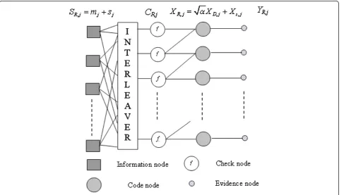
The RA code structure can be described with the well-known Tanner graph, which is the basis to use the belief propagation algorithm [26]. The tanner graph of the vir-tual encoder at the relay is drawn on Figure 3.
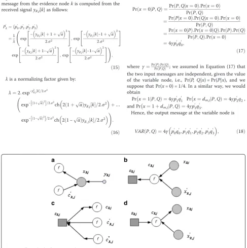
For the decoding algorithm, we have the four following configurations of message updating steps (see Figure 4). The decoding algorithm proceeds as follows. We suppose, for example, that we use a MIMO ZF-based equalizer, this entails the multiplication of the received signal yRby the invert or the pseudo-invert matrix ofHR. Hence, after the ZF equalization step at the relay, assuming a BPSK modu-lation scheme, the kth received symbol at thejth row of the received vector at the relay is written as:
Another solution may consist in employing a list sphere decoder [27] to weight the coded symbol before entering the belief propagation decoding module. This affords to obtain better performances than using ZF equalization since it is well known that LSD, which ap-proximates the ML solution, exhibits better perfor-mances compared to ZF equalization.
Concerning the decoding algorithm using BP, it pro-ceeds as follows. LetP[h,t] denote the message passed be-tween a check node and a variable node (information node or code node), the message is associated with the edge from node h to node t; one of h or t is a variable node and the other is a check node. As in [19,20], we de-notePkas the message from thekth evidence node to the kth code node. Hence, we have the following notations:
P[h,t] = (p0,p1,p2) is a vector, in whichpiis the prob-ability that the corresponding variable node (h or t) takes on the valuei. In fact, we have
p0¼Pr mjþsj
l ½ ¼0
p1¼Pr mjþsj
l ½ ¼1
p2¼Pr mjþsj
l ½ ¼2
: ð13Þ
The messages for the variable nodes are initialized to (1/4, 1/2, 1/4).
Similarly, P0k¼ p
0
0;p
0
1;p
0
2;p
0
3
is a vector, in which p′i is the probability that the kth coded symbol is i given thekth received symbol. We have here:
Figure 3The virtual encoder for ACNC.
p00¼Pr
Initialization step: all the messages with the edges in Figure 4 are taken equal to (1/4, 1/4, 1/4, 1/4) except for the messages incident to the evidence nodes. These mes-sages contain information on the received signal and the message from the evidence nodekis computed from the received signalyR,j[k] as follows:
λis a normalizing factor given by:
λ¼2:exp−y2R;j½ k=2:σ2
3.3 Message update rules
(a) The first update rule concerns the update equations for Output Messages going out of a Variable Node. This corresponds to the cases of Figure 5a,c.
Figure 5a case: when the probability vectors of the two input messages, P0¼ p00;p
(associated with the edge fromytoxand from c'to x) arrive at a code node of degree 3 (except the lowest code node), the probability that the code symbol is 0 is obtained as follows:
Prðx¼0jP;QÞ ¼PrðP;Qjx¼0Þ:Prðx¼0Þ the two input messages are independent, given the value of the variable node, i.e., Pr(P, Q|x) = Pr(P|x), and we
Hence, the output message at the variable node is
VAR Pð ;QÞ ¼4γ p00q
Withγ¼ 1
– (1) The update equations for the scenario of Figure5care similar except that the variable node is an information node rather than a code node, and the associated probabilities are related to the source symbol rather than the code symbol.
– (2) If we consider the messages in log-likelihood (LLR) form, i.e.,pk0 ¼0;logp01=p00;logp20=p00;logp30=p00, we find that Equation (17) is equivalent to the summa-tion of all the incoming LLRs.
– (3) For the lowest code node in Figure4, the output message is always the same at the input message from the last evidence node, which remains constant throughout the iterations.
(b) The second update rule concerns the update equa-tions for Output Messages going out of a Check Node. This corresponds to the cases of Figure 5b,d.
Figure 5bcase: If we consider a check node below the topmost check node, the probability that the informa-tion node symbol is 0 given the two input messages P0¼ p00;p spectively) is equal to:
Prðx¼0jP;QÞ
Figure 5d case: in this case, we have two messages coming fromc0R;jandc
And, similarly, we obtain
p2¼Prð mjþsj
We reuse Equations (5) and (11), we have
yR¼HR ffiffiffiα p
mþs
ð Þ þnR
yD¼~t′þHHRDnD :
have supposed that there is no direct link between sen-sor nodes and destination nodes the upper bound for the achievable data rate at the destination node can be approximated by [28]:
C¼1
2E½minðlog2½det Iþ
ρRD
K H
−1
RD H−RD1
H
;… …log2½det IþρSR
K HRðHRÞ H
:
ð27Þ
Where the factor 0.5 denotes the half multiplexing loss due to relaying compared with a relay-free scenario.ρSR denotes the signal-to-noise power ratio for the link be-tween sensors and relay and ρRD denotes the signal to noise power ratio for the link between relay and destin-ation. In the following, supposing that the relay is lo-cated at the same distances from the sensor network and the destination, we will assume that:ρSR=ρRD=ρ
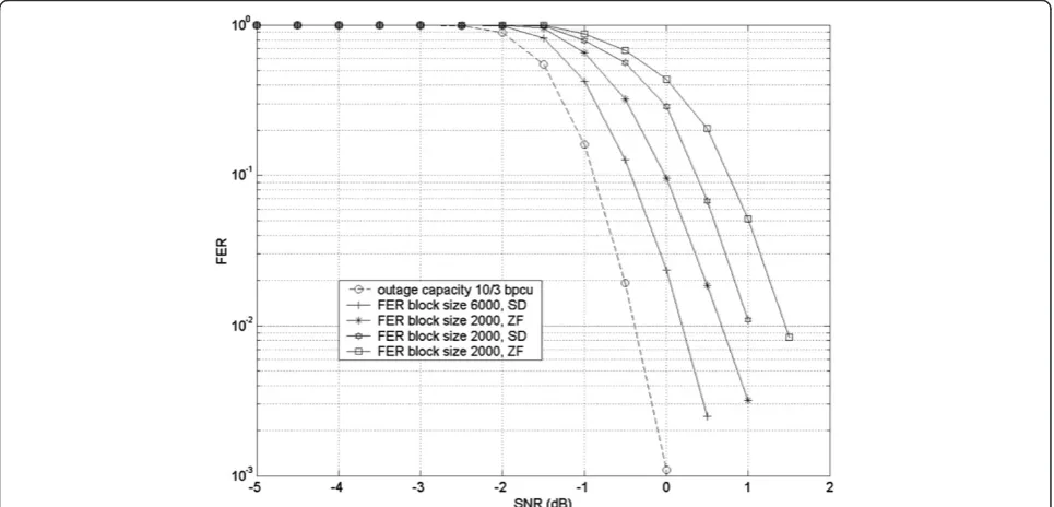
We consider a sensor network with respectively four, six, eight, and ten sensors, and we deal with the case of Figure 6The performance results of the proposed network scheme at outage capacity 4/3 bpcu.
a BPSK modulation at both sensor and destination nodes. We set the repeat factorqto 3 and the interleave pattern is randomly selected for each packet. This entails a coding rate of 1/3. The simulated channel models are quasi static block fading channels, i.e., the channel pa-rameters stay fixed for the duration of a transmitted block but vary from block to block. No power optimization is done, i.e., that means that transmit power at the destination source and at the sensor nodes
is normalized to one. We compare the performances of two decoding schemes using a ZF equalizer or a sphere detector before BP decoding. We consider two size blocks for the RA encoder scheme: 2,000 and 6,000 bits. The performance results of the proposed network scheme are illustrated on Figures 6, 7, 8, and 9. The con-clusions are nearly the same for each picture. Working with the highest block size, i.e., 6,000 bits together with a SISO (Soft In Soft Out) Sphere Decoder [27] enables Figure 8The performance results of the proposed network scheme at outage capacity 8/3 bpcu.
to work close to the theoretical capacity of formula (27). For example, for a ten-sensor network, we are able to work within less than 1 dB from the achievable data rate at a Frame Error Rate (FER) of 10−2(see Figure 9). The use of receiver architecture equipped a ZF equalizer yields to a degradation approximately equal to 0.6 0.7 dB, thus enabling to work within 1.7 dB from the ergodic capacity. The degradation is clearly more im-portant when we use a small size RA block code. With a block size of 2,000 bits, the performances of a SD-based receiver are nearly 2 dB far away from the ergodic cap-acity at FER = 10−2 (see Figure 8). Concerning the re-ceiver with a ZF equalizer, we are nearly 2.5 dB from the ergodic capacity (once again for the case FER = 10−2).
All of these results constitute an outstanding perform-ance since we are able, in all the cases, to work close to the theoretical ergodic capacity of the system.
5 Conclusion
In this paper, we have proposed a physical network coding-based system to improve the throughput efficiency of a wireless sensor network. Thanks to powerful beam-forming techniques, supposing that the relay and the des-tination are equipped with K antennas, we built a new transmission protocol which enables 2.K uplink and downlink transmissions to be accomplished within (K+ 2) time slots. This outstanding performance is obtained be-cause we found a way to handle the co-channel interfer-ence despite the poor capacities of elementary wireless sensors which have only one antenna.
Furthermore, since our proposed scheme is fully com-patible with the physical network coding (PNC) princi-ples, we propose a distributed coding scheme where channel coding is applied at the destination and at the sensors level and network coding is applied at the relay to encode the incoming mixed streams from the destin-ation and the sensors. We show that our proposed sys-tem enables to transmit simultaneously the K encoded messages from the sensors and the control encoded messages from the destination. Simulation results dem-onstrate that our proposed distributed coding scheme enables to work close to the theoretical ergodic capacity of the system. Typically, considering different kinds of receiver architectures, we are always within less than 2 dB from the ergodic capacity of the equivalent system.
Competing interests
The authors declare that they have no competing interests.
Authors' information
NA received the engineering degree from the Ecole Nationale Supérieure d'Ingénieurs de Limoges in September 2010. He is now a PhD student at the University of Limoges since October 2010. His research activities concern the cooperative communication in mobilead hocnetworks, especially for physical and MAC layer. He is also a temporary teacher at the University of Limoges; he participated in many international conferences.
VM received the BSc and MSc degrees from Sharif University of Technology, Tehran, Iran, respectively, in 1988 and 1991 and PhD degree from the University of Limoges, France in 1998. He has been working at the department of electronic and telecommunication of ENSIL/University of Limoges as an assistant professor since 2000 and as an associate professor since 2007. He received in 2008 and 2012 from the French ministry of research and higher education the award of scientific excellence. His main interest in research is the telecommunication systems including MIMO systems, coding, network coding, cooperative communications, sensor network, and smart grid. Since 1998, he has been scientific manager for more than ten research projects in the field of ICT (information and Communications Technology). He is the (co-)author of more than 100 publications in scientific journals and conferences and served as TPC members in several international conferences.
JPC received the engineering degree from the Ecole Nationale Supérieure des Télécommunications de Bretagne in 1990. He also received the Aggregation degree in Physics in 1993 and the HDR degree in 2002 from the University of Limoges. He became a IEEE senior member in 2007. He is now a full professor in signal processing at the Ecole Nationale d'Ingénieurs de Limoges (ENSIL) since 2006. His research activities concern signal processing algorithms for digital communications including cooperative networks, network coding, space-time coding, and joint optimization of physical and MAC layers of future communication systems. He is getting in-volved in several French and European research programs.
Received: 3 April 2013 Accepted: 16 October 2013 Published: 16 November 2013
References
1. S Katti, H Rahul, W Hu, D Katabi, M Medard, J Crowcroft, Xors in the air: practical wireless network coding, inProc ACM SIGCOMM(Pisa, 2006), pp. 243–254
2. Z Ding, KK Leung, DL Goeckel, D Towsley, On the study of network coding with diversity. IEEE Trans. Wireless Commun.8, 1247–1259 (2009) 3. RHY Louie, Y Li, B Vucetic, Practical physical layer network coding for two-way
relay channels: performance analysis and comparison. IEEE Trans. Wireless Commun.9, 764–777 (2010)
4. P Popowski, H Yomo,Physical network coding in two-way wireless relay channels. Proc. IEEE Int. Conf on Comm. (ICC) (, Glasgow, 2007), pp. 707–711 5. C Fragouli, J Widmer, JYL Boudec,A network coding approach to energy
efficient broadcasting: from theory to practice, in Proc IEEE Conf Comput. Commun. (Infocom)(Barcelona, 2006)
6. Y Chen, S Kishore, J Li, Wireless diversity through network coding, inProc. IEEE Wireless Commun. Netw. Conf. (WCNC)(Las Vegas, NV, 2006), pp. 1681–1686 7. A Asterjadhi, E Fasolo, M Rossi, J Widmer, M Zorzi, Toward network
coding-based protocols for data broadcasting in wireless ad hoc networks. IEEE Trans. Wireless Commun.9, 662–672 (2010)
8. Z Ding, T Ratnarajah, KK Leung, On the study of network coded at transmission protocol for wireless multiple access channels. IEEE Trans. Wireless Commun.8, 118–123 (2009)
9. Y Meng, L Jing, RS Blum,User cooperation through network coding. Proc. IEEE Int. Conf on Comm. (ICC) (Glasgow, 2007), pp. 4064–4069
10. X Bao, J Li,Matching code-on-graph with network-on-graph: adaptive network coding for wireless relay channels. Proc of Allerton Conference on Communication, Control and Computing (Urbana Champaign, IL, 2005) 11. X Bao, J Li, Adaptive network coded cooperation (ANCC) for wireless relay
networks: matching code-on-graph with network-on-graph. IEEE Trans. Wireless Commun.7, 574–583 (2008)
12. P Kun, L Yonghui, B Vucetic,Joint network-channel code design for real wireless relay networks. Proc. 6th Int. Syp. On Turbo Codes and Iterative Inf. Proc. (ISTC) (Brest, 2010), pp. 429–433
13. VR Cadambe, SA Jafar, Interference alignment and the degrees of freedom for the k user interference channel. IEEE Trans. Inform. Theory.54, 3425–3441 (2008) 14. J Li, W Chen, Joint power allocation and precoding for network coding-based
cooperative multicast systems. IEEE Sig. Proc. Letters.15, 817–820 (2008) 15. D Zhiguo, I Krikidis, J Thompson, KK Leung, Physical layer network coding
and precoding for the two-way relay channel in cellular systems. IEEE Trans. Sig. Proc.59, 696–712 (2011)
17. DHN Nguyen,Distributed beamforming in relay-assisted multiuser communi-cations. Proc. IEEE Int. Conf on Comm. (ICC) (Dresde, 2009)
18. F Sun, E De Carvalho, E Popovski, CDT Thai, Coordinated direct and relay transmission with linear non-regenerative relay beamforming. IEEE Sig. Proc. Letters.19, 680–683 (2012)
19. S Zhang, SC Liew, Joint design of physical-layer network coding and channel coding. doi:arXiv:0807.4770
20. S Zhang, SC Liew, Channel coding and decoding in a relay system operated with physical-layer network coding. IEEE JSAC27, 788–796 (2009) 21. Y Lang, D Wübben, KD Kammeyer,An improved physical layer network
coding scheme for two-way relay systems. International ITG Workshop on Smart Antennas (WSA 2010) (Bremen, 2010), pp. 107–114
22. D Wübben, Y Lang,Generalized sum-product algorithm for joint channel decoding and physical-layer network coding in two-way relay systems. IEEE Globecom (Miami, FL, 2010)
23. K Gomadam, VR Cadambe, SA Jafar,Approaching the capacity of wireless networks through distributed interference alignment. Proc IEEE Global Telecommunications Conference Globecom (New Orleans, LO, 2008) 24. RA Horn, CR Johnson,Matrix analysis(Cambridge University Press,
New York, 1985)
25. S Zhang, SC Liew, L Lu,Physical layer network coding schemes over finite an infinite fields. Proc IEEE Global Telecommunications Conference Globecom (New Orleans, LO, 2008)
26. FR Kschischang, BJ Frey, HA Loeliger, Factor graphs and the sum-product algorithm. IEEE Trans. Inform. Theory.47, 498–519 (2001)
27. AD Kora, A Saemi, JP Cances, V Meghdadi, New list sphere decoding (LSD) and iterative synchronization algorithms for MIMO-OFDM detection with LDPC-FEC. IEEE Trans VehTechnol.57, 3510–3524 (2008)
28. Y Fan, J Thompson, MIMO configurations for relay channels: theory and practice. IEEE Trans. Wireless Commun.6, 1774–1786 (2007)
doi:10.1186/1687-1499-2013-267
Cite this article as:Alaouiet al.:Joint network-channel code optimization for wireless sensor networks.EURASIP Journal on Wireless Communications and Networking20132013:267.
Submit your manuscript to a
journal and benefi t from:
7Convenient online submission
7Rigorous peer review
7Immediate publication on acceptance
7Open access: articles freely available online
7High visibility within the fi eld
7Retaining the copyright to your article