Design of 2.4GHz patch antenna array for
wireless applications
Kalyani.B1 , Divyadeepthi.K2, Eswari Sai Leela.B3, Pavani.K4 , G.Naveen Kumar5
UG Students, VVIT, Guntur, A.P, India.1,2,3,4
Assistant Professor, Dept. of ECE, VVIT, Guntur, A.P, India..5
ABSTRACT: in high performance applications where size, weight, cost and is of installation are constraints. For the applications such as aircraft, spacecraft and satellite and missile require low profile antennas. Patch antenna array exhibit wider band width and pencil beam directivity. The patch antenna concept has been used in patch antenna designed to increase patch antenna directivity. The structure of an antenna is simple to manufacture, versatile in nature and due to the small size it can be embedded in various portable devices. As Micro strip patch antenna array is best for its s-band characteristics, we prefer this. In these the patch antenna can be designed for WLAN, s-band and Bluetooth application by providing an array fed by coaxial cable. It has wireless applications which require pencil beam radiation pattern such as for covering wireless applications of WLAN. By using mat lab software package the parameters of the propose antenna are described and simulated using MATLAB software package.
KEYWORDS: antenna, low profile antenna, patch antenna array, s-band, coaxial cable, MATLAB
I.INTRODUCTION
Antenna array also called as array antenna, antenna arrays are several antennas connected and arranged in a regular structure to form a single antenna. Phased array antenna (PAA) is a multiple antenna system, in which that the radiation pattern can be rain forced in a particular direction and suppressed in desired direction. The direction of phased array radiation can be electronically starred obviating the need for any mechanical rotation. These unique capabilities found that the phased arrays a broad range of applications since the advent of this advanced technology. The single micro strip patch antenna fed with coaxial cable was firstly introduced by HUYNH and Lee in 1995 the advantage of using patch antenna is, the directivity increases. It is a low profile antenna, able to adapt to mini activities and can be easily carried. Patch antennas are mainly used in aircrafts, space, satellite and mobile communications.
In patch antennas,charecteristics such as high gain,bean scanning,or steering[3] capability are possible only when discrete patch elements are combined to form arrays.the elements of an array may be spacially distributed to form a linear,planar,or volume array.planar arrays have elements distributed on a plane.planar array configuirations are extensively used in both communication[2] and radar systems where a narrow pencil beam is requied.individual elements can be positioned along a rectangular grid to form a planar array for better control of beam shape and position in space.planar arrays of printed radiating elements are potentially good candidates for low cost scanning array applications.microstrip patch arrays are versatile asa they can be used to synthesize a requied pattern that cannot be achieved with a single element.in addition,they are used to increase the directivity[4] and perform various other functions,which would be difficult with any one single element.
structure is closely spaced, the returns loss improves in E plane.it has been shown that with the increasing array spacing,the gain of the antenna gets reduced significantly.
THE MAJOR ADVANTAGES OF ANTENNA ARRAYS ARE: Increase the overall gain.
Provide diversity reception.
Cancel out interference from a particular set of directions.
Fig.1: Three dimensional view of single patch antenna
The above figure shows the schematic view of single patch antenna.it consists of a patch element,ground plane and dielectric.the patch element is feed by using coaxial cable.width(w) and length(l) of patch are used for increase of decrease the antenna parameters.
II. PROPOSED ANTENNA DESIGN
Fig.2:Rectangular patch antenna array
The configuration of above suggested rectangular patch antenna is shown in Fig.1.The fundamental shape of the patch antenna array as shown in Fig.2.
TABLE 1
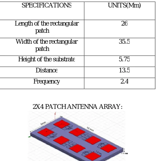
SPECIFICATIONS OF THE PATCH ANTENNA
SPECIFICATIONS UNITS(Mm)
Length of the rectangular patch
26
Width of the rectangular patch
35.5
Height of the substrate 5.75
Distance 13.5
Frequency 2.4
2X4 PATCH ANTENNA ARRAY:
The above figure shows the schematic of 2×4 patch antenna array.in this design, it consists of 2 rows and 4 columns of patch antenna elements.
TABLE 2
SPECIFICATIONS OF THE PATCH ANTENNA
SPECIFICATIONS UNITS Radiated power(W) 0.0611568
Frequency(GHz) 2.4 Antenna efficiency(%) 76.446
Gain(dB) 15.9317 Directivity(dB) 17.0981 3 dB beam width(deg) (8.10355,81.3166)
Incident poer(W) 0.08 Input power(W) 0.0657195
Average radiated power(W/S)
Radiated efficiency(%) 73.0573
Radiated efficiency in upper space(%)
89.0573
Radiated efficiency in lower space(%)
3.54159e-009
III. DESIGN CONFIGURATION
Width of Patch antenna is given by
Where c is the velocity of light and εr is the value of dielectric constant. Here εr=1
Length of patch antenna is given by
The resonant frequency for any modeis given by
The Directivity of the patch antenna is given by
Coaxial-probe feeding technique is one of the most flexible and commonly using technique for patch antenna because the feed can be located at any desired location in patch in order to match with its input impedance. Here the feed diameter is given as 0.5mm.
IV. SIMULATION RESULTS
Fig.4:3D Directivity Pattern of Rectangular Array
The directivity pattern of rectangular arrays have the isometric radiation pattern .i.e; the radiation is same in all directions. We need pencil beam radiation pattern for wireless applications ,so that we need to increase the directivity of the antenna.for that purpose we need to design arrays.here we taken 2×4 and 3×3 patch antenna arrays.
Fig.5: 3D Directivity pattern of 2x4 patch antenna array
The above fig. Shows the directivity pattern of the 3×3 patch antenna array. From the fig. We observed that it contains major lobe, side lobs and back lobe .so that we are increased the directivity of the antenna array.
Fig.7: Reflection coefficient graph of patch antenna array
The above fig. Gives the graph between magnitude in db and frequency in Hz. So that we can easily analyze the characteristics of antenna array
Fig.8: Impedance behaviour of patch antenna array
Fig.9: Radiation pattern along elevation direction
The above figure gives the graph between directivity in db and azimuth angle in degree. From the graph we observed that the directivity is increased.
Fig.10: Radiation pattern along azimuth direction
The above figure gives the graph between directivity in db and elevation angle in degree.From the graph we conclude that the directivity was increased.
V. CONCLUSION
REFERENCES
[1]. Balanis, C. A. (2005). Antenna theory analysis and design (3rd ed.). Wiley Publication.
[2]R.A. Saed, S. Khatun, "Design of Microstrip Antenna for WLAN", Journal of Applied Sciences, vol. 5, no. 1, pp. 47-51, May 2005.
[3]Elftouhl Hanae, A. Touhami Naima, Mohamed Aghoutane, "Miniaturized Microstrip Patch Antenna with Defected Ground Structure", Progress In Electromagnetic ResearchC, vol. 55, pp. 25-33, 2014.
[4] Anguera, J., Montesinos, G., Puente, C., Borja, C., Soler, J. "An under-sampled high directivity microstrip patch array with a reduced number of radiating elements inspired on the Sierpinski fractal", Microwave and Optical Technology Letters, Vol. 37, No. 2, pp. 100-103, 2003.
[5] Subbulakshmi, P. and Rajkumar, R., "Design and characterization of corporate feed rectangular microstrip patch array antenna", International Conference on Emerging Trends in Computing, Communication and Nanotechnology (ICE-CCN), pp. 547 – 552, 2013.