ISSN(Online): 2319-8753 ISSN (Print) : 2347-6710
I
nternational
J
ournal of
I
nnovative
R
esearch in
S
cience,
E
ngineering and
T
echnology
(An ISO 3297: 2007 Certified Organization)
Vol. 5, Issue 6, June 2016
Design, Modelling and Implementation of
Variable FFT Processor
Mujtaba Afzal1, Dayal Sati2, Heena Choudhary3, Ashish Vats4, Romika Choudhary5
M. Tech Scholar, Assistant Professor2; Dept. of Electronics & Communication Engineering, BRCM College Of
Engineering & Technology, Bahal-Haryana, India1,2
Assistant Professor, Dept. of Electronics &Communication Engineering, Swami Vivekananda Subharti University,
Meerut, India3
Assistant Professor, Manav Rachna International University, Faridabad, Haryana, India4,5
ABSTRACT: the research paper focuses on the Design, Modeling and Implementation of Variable FFT Processor. FAST Fourier transform (FFT) is a main block in orthogonal frequency division multiplexing (OFDM) and Orthogonal Frequency-Division Multiple Access (OFDMA) systems. OFDM has been adopted in a wide range of applications from wired-communication modems, such as wireless-communication modems, Wi-Fi, IEEE802.16, Wi-MAX or 3GPP long term evolution (LTE), digital subscriber lines (xDSL), to process baseband data. In the paper first the design is carried for 8 point FFT and further it is used to implement variable FFT processor. The design is developed with the help of VHDL programming language and synthesized on Virtex-5 FPGA in Xilinx 14.2 software and functional simulation is done in Modelsim 10.1.
KEYWORDS: Fast Fourier Transform (FFT), Field Programmable Gate Array (FPGA), Orthogonal Frequency-Division Multiple Access (OFDMA)
I. INTRODUCTION
Orthogonal Frequency-Division Multiple Access (OFDMA) is a multi-user version of the popular Orthogonal frequency-division multiplexing (OFDM) digital modulation scheme. The FFT and IFFT pairs are used to modulate and demodulate the data constellation on the subcarriers, in the widely used OFDM systems. In such applications there is the need of variable FFT. Variable FFT is also used in Multiple input multiple output (MIMO) OFDM systems. With the rapid growth of digital communication in recent years, there is the need for high-speed data transmission with faster rate. The mobile telecommunication industries are facing the problem of providing the technology that be able to support a variety of services ranging from voice communication with a bit rate of a few kbps to wireless multimedia in which bit rate up to 2 Mbps. Couple of systems have been proposed to resolve the problem and OFDM system has gained much attention for different reasons. OFDM technique was first developed in the 1960s. Only in recent years, OFDM has been recognized as an outstanding method for high speed cellular data communication where its implementation relies on very high speed digital signal processing applications. The method has only recently become available with reasonable prices versus performance of hardware implementation. The fundamental principle of the OFDM system is to decompose the high rate data stream (bandwidth = W) into N lower rate data streams and then to transmit them simultaneously over a large number of subcarriers [13]. The modulation and demodulation of data constellations on the orthogonal subcarriers is done with the help of IFFT and FFT respectively.
II.RADIX-2 FFT
ISSN(Online): 2319-8753 ISSN (Print) : 2347-6710
I
nternational
J
ournal of
I
nnovative
R
esearch in
S
cience,
E
ngineering and
T
echnology
(An ISO 3297: 2007 Certified Organization)
Vol. 5, Issue 6, June 2016
( ) = ( ) / , ≤ ≤ − (1)
The equation can be represented by the relation-
( ) = ( ) / = ( ) , ≤ ≤ − (2)
Here WN represents the complex valued phase factor, which is the Nth root of unity and expressed as = / Similarly the equation of IDFT is given as –
( ) = ( ) ≤ ≤ − (3)
From the above equations it is clear that for each value of k, the direct computation of X (k) require N complex multiplications (4N real multiplications and N-1 complex additions (4N-2 real additions). Hence to compute all N values of DFT, there is the requirement of N2 complex multiplications and N (N-1) complex additions.
To compute the N point DFT, the equation is given by-
( ) = ( ) + ( ) = ( ) + ( ) −
Where x (n) is a complex valued sequence, and XR and XI represents the real and imaginary parts. If we equate the real and imaginary parts separately, the above equation will be given by-
( ) = ( ) + ( ) (4)
( ) =− ( ) − ( ) (5)
There is the requirement of 2N2 Trigonometric evaluations to compute DFT directly.4N2 real multiplications and 4N (N-1) real additions. It is primarily inefficient as it does not exploit the periodicity and symmetry properties of Weight function or phase factor WN, which is given by
/
=− (6) = (7)
The solution of the two properties of DFT is the fast Fourier transform (FFT), which is an efficient algorithm can exploit the above two equations.
A computationally efficient algorithm is developed for DFT by the adoption of divide and conquers approach. This approach is based on the decomposition rule of N point DFT into smaller size successive DFTs. If N is factored as N = r1r2r3 …….. rL. Where r1= r2 = …… = rL = r, then N = rL. Hence, the DFT will be of size ‘r, where this number ‘r’ is known as radix of the FFT algorithm. This algorithm has the advantage of periodicity and symmetry of complex numbers
=
Decimation in Time (DIT) Algorithm of FFT
When the FFT algorithm is applied in time domain, it is called DIT FFT algorithm. Decimation refers to the significant reduction in number of calculations performed on time domain data. The computational redundancy inherent in the DFT is used to reduce the significant calculations which help in the speed up of DFT. Let x (n) is the sequence of N values, where N is the integer value and power of 2, that is N = 2L. This power is divided into two N/2 point sequence and a combination of even and odd numbered values of x (n). For a sequence x (n) the equation of N point DFT is given by-
ISSN(Online): 2319-8753 ISSN (Print) : 2347-6710
I
nternational
J
ournal of
I
nnovative
R
esearch in
S
cience,
E
ngineering and
T
echnology
(An ISO 3297: 2007 Certified Organization)
Vol. 5, Issue 6, June 2016
Decimating into even and odd numbered sequence, it can be written as-
( ) = ( )
,
+ ( )
,
(9)
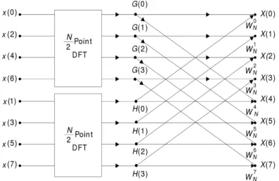
Fig. 1 shows the graph of decimation in time algorithm for 8 point (N=8) DFT computations. 8 point DFT is grouped into two 4 point DFT computations. Here a node variable is presented with the branches entering a node. If there is no coefficient it means the value of branch transmittance is equal to one. For the other branches the transmittance is a power of WN.
Fig.1 Flow graph of Decimation in Time FFT (for N=8) Algorithm
The value of X (0) is obtained by the multiplication of H (0) by and adding the production to G (0).X (1) is obtained by the multiplication H (1) by and adding the result with G (1). For X (4), H (4) value is multiplied with and added with G (4). Because G (k) and H (k) are periodic in nature with period 4. Here H (0) = H (4) and G (4) = G (0). Hence X (4) is obtained by the multiplication of H (0) by and adding the result to G (0).If the direct computation is done for an N point DFT, with symmetry property; there is the requirement of N2 complex multiplications and ( −
ISSN(Online): 2319-8753 ISSN (Print) : 2347-6710
I
nternational
J
ournal of
I
nnovative
R
esearch in
S
cience,
E
ngineering and
T
echnology
(An ISO 3297: 2007 Certified Organization)
Vol. 5, Issue 6, June 2016
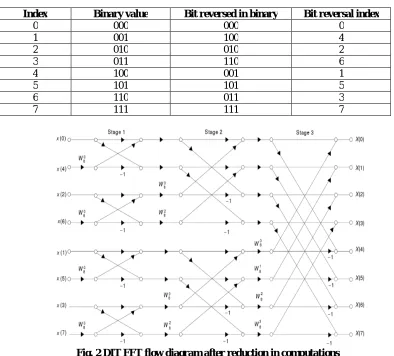
Table 1 Bit reserved in binary
Index Binary value Bit reversed in binary Bit reversal index
0 000 000 0
1 001 100 4
2 010 010 2
3 011 110 6
4 100 001 1
5 101 101 5
6 110 011 3
7 111 111 7
Fig. 2 DIT FFT flow diagram after reduction in computations
ISSN(Online): 2319-8753 ISSN (Print) : 2347-6710
I
nternational
J
ournal of
I
nnovative
R
esearch in
S
cience,
E
ngineering and
T
echnology
(An ISO 3297: 2007 Certified Organization)
Vol. 5, Issue 6, June 2016
Fig.3 FFT Input and output block
III. FFT PROCESSOR DESIGN
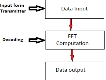
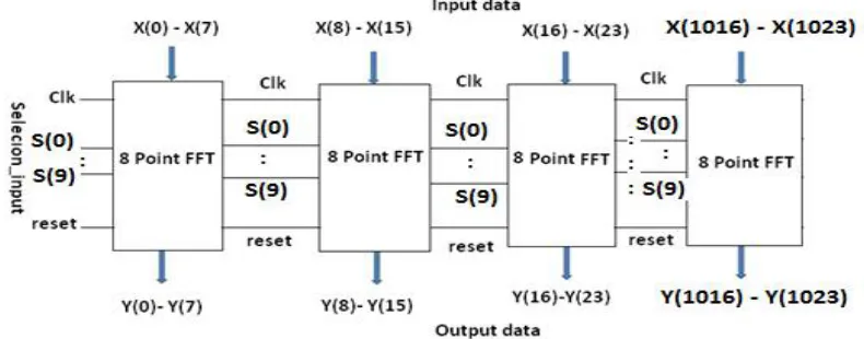
The operation of the FFT processor is partitioned into three main processes. These are the Data Input, FFT Computation and Data Output Processes as shown in fig. 4. The 1024 point FFT processor can be designed using four 8-point FFT processors. Figure 6 shows the input and outputs of 1024 point FFT with clock and reset. Instead of direct implementing 1024 point FFT, It is possible to achieve faster speed of 1024 bit processor because it will support parallel processing or pipelined architecture as shown in fig. 5. In 1024 point FFT computation, only 8 point FFT is computed one time. The operation can be controlled with the selection logic which process 8 points at one time. Tables 2 explain the selection and computation processing of 1024 point FFT.
Fig. 4FFT Computation Process
ISSN(Online): 2319-8753 ISSN (Print) : 2347-6710
I
nternational
J
ournal of
I
nnovative
R
esearch in
S
cience,
E
ngineering and
T
echnology
(An ISO 3297: 2007 Certified Organization)
Vol. 5, Issue 6, June 2016
Fig. 6Structure of 1024 point FFT
Table 2 Computation and Selection logic of 1024 point FFT
(S0 S9)
Selection
Computation
0000000000 FFT 1 selection for input X(0) to X(7) and Corresponding output Y(0)-Y(7)
0000000001 FFT 2 selection for input X(8) to X(15) and Corresponding output Y(8)-Y(15)
0000000010 FFT 3 selection for input X(16) to X(23) and Corresponding output Y(16)-Y(23)
0000000011 FFT 4 selection for input X(24) to X(31) and Corresponding output Y(24)-Y(31)
:: ::
1111111111 FFT 128 selection for input X(1016) to X(1023) and Corresponding output Y(1016)-Y(1023)
IV. SIMULATION AND SYNTHESIS RESULTS
ISSN(Online): 2319-8753 ISSN (Print) : 2347-6710
I
nternational
J
ournal of
I
nnovative
R
esearch in
S
cience,
E
ngineering and
T
echnology
(An ISO 3297: 2007 Certified Organization)
Vol. 5, Issue 6, June 2016
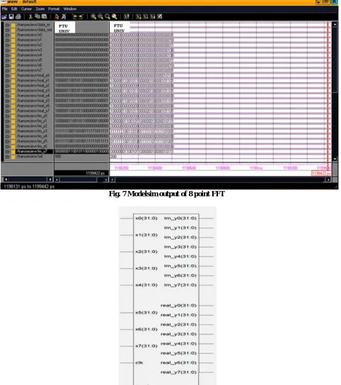
Fig. 7 Modelsim output of 8 point FFT
ISSN(Online): 2319-8753 ISSN (Print) : 2347-6710
I
nternational
J
ournal of
I
nnovative
R
esearch in
S
cience,
E
ngineering and
T
echnology
(An ISO 3297: 2007 Certified Organization)
Vol. 5, Issue 6, June 2016
Table 3 Detail of Pin used in RTL of 8 Point FFT
Pin Description
x(0) – x(7) Input of 8 point FFT
Clk Input to 8 point FFT used to provide positive (Rising edge) of clock pulse
Reset Input which is used to reset the FFT contents in memory
Im-y(0) to im_(7) Represent the imaginary output of 8 point FFT, separated from output Real_(0) to Real_(8) Represent the real output of 8 point FFT, separated from output
Device utilization summary of 1024 point FFT
The synthesis report shows the complete details of device utilization. Device utilization summary is the report of used device hardware in the implementation of the chip such as RAM, ROM, slices, flip flops etc. If the designed chip is not having the optimized hardware parameters, further chip development is done in the Xilinx ISE design software. Table 4 shows the hardware utilization for the staged structure. Target Device: xc5vlx20t-2-ff323, Virtex 5, is the device targeted for FPGA. Timing details provides the information of delay, minimum period, minimum input arrival time before clock and maximum output required time after clock. Table 4 lists the details of minimum period, maximum frequency, and minimum input arrival time before clock, and maximum output required time after clock and memory utilization for three stage networks.
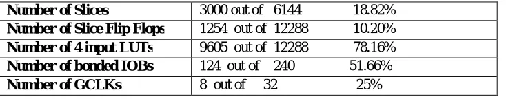
Table 4Device utilization summary of 1024 point FFT implemented using 8 point FFT
Number of Slices 3000 out of 6144 18.82%
Number of Slice Flip Flops 1254 out of 12288 10.20%
Number of 4 input LUTs 9605 out of 12288 78.16%
Number of bonded IOBs 124 out of 240 51.66%
Number of GCLKs 8 out of 32 25%
Table 5 Timing Parameters Summary of 1024 point FFT
Speed Grade -8
Minimum period 1.119 ns
Maximum Frequency 400 MHz
Minimum input arrival time before clock 2.352ns
Maximum output required time after clock
5.967ns
Maximum combinational path delay 18.058 ns
Total memory usage is 445610 kilobytes
Global Maximum Fan-out 500
Add Generic Clock Buffer(BUFG) 32
Number of Regional Clock Buffers 16
Optimization Goal Speed
Slice Utilization Ratio 100
DSP48 Utilization Ratio 100
ISSN(Online): 2319-8753 ISSN (Print) : 2347-6710
I
nternational
J
ournal of
I
nnovative
R
esearch in
S
cience,
E
ngineering and
T
echnology
(An ISO 3297: 2007 Certified Organization)
Vol. 5, Issue 6, June 2016
V. CONCLUSION
The design and implementation of variable FFT processor of length N=1024 is done for OFDMA application and synthesized on Virtex-5 FPGA successfully. The design is simulated for different test cases and analyzed with discrete inputs. The design is based on the parallel computation logic and having faster speed and supporting frequency of 400 MHz FAST Fourier transform (FFT) is a crucial block in Orthogonal Frequency Division Multiplexing (OFDM) systems. In the decoding of OFDMA system variable FFT is used. The proposed design can be applied for Multiple input multiple output (MIMO) OFDMA system.
REFERENCES
[1] A. Cortes, I. Velez, and J. F. Sevillano, “Radix rk FFTs: Matricial representation and SDC/SDF pipeline implementation,” IEEE Trans.Signal
Process., vol. 57, no. 7, pp. 2824–2839, Jul. 2009.
[2] A. V. Oppenheim and R. W. Schafer, Discrete-Time Signal Processing. Englewood Cliffs, NJ: Prentice-Hall, 1999.
[3] A. Raghunathan , S. Dey, N. K. Jha, “High-level macro-modeling and estimation techniques for switching activity and power consumption”, Very Large Scale Integration (VLSI) Systems, IEEE Transactions on, Vol. 11, Issue 4, Aug. 2003 Page(s):538 – 557.
[4] E. E. Swartzlander, W. K. W. Young, and S. J. Joseph, “A radix 4 delay commutator for fast Fourier transform processor implementation,”
IEEEJ. Solid-State Circuits, vol. 19, no. 5, pp. 702–709, Oct. 1984.
[5] B. G. Jo and M. H. Sunwoo, “New continuous-flow mixed-radix (CFMR) FFT processor using novel in-place strategy,” IEEE Trans.Circuits
Syst. I, Reg. Papers, vol. 52, no. 5, pp. 911–919, May 2005.
[6] C.-L. Hung, S.-S. Long, and M.-T. Shiue, “A low power and variable length FFT processor design for flexible MIMO OFDM systems,” in Proc.
IEEE Int. Symp. Circuits Syst., May 2009, pp. 705–708
[7] S Salivahanan, “C Gnanapriya “Digital Signal Processing” Second Edition Tata McGraw Hill Education Private Limited, New Delhi. 2011. [8] Loo Kah Cheng, “Design of an OFDM Transmitter and Receiver using FPGA”, UTM, thesis 004.
[9] M. Karunaratne, C. Ranasinghe, A. Sagahyroon, “A dynamic switching activity generation technique for power analysis of electronic circuits,”
Circuit and Systems, 2005, 48thMid west Symposium on, Page(s) 1884-1887 Vol.2, 7-10 Aug. 2005.
[10] Y.-T. Lin, P.-Y. Tsai, and T.-D. Chiueh, “Low-power variable-length fast Fourier transform processor,” IEE Proc. Comput. Digital Tech., vol.