Abstract
ACHARYA, MITHUN PUTHIGE. NAMO NAMAHA:N
¯etworkA¯ssistedM¯ulticastO¯verlay ConstructioN
¯ A¯lgorithms for M¯obile A¯d H¯ocA¯pplications (Under the direction of
Dou-glas S. Reeves)1. Group communication is the most important mode of communication
in ad hoc networks, because of the collaborative nature of mobile ad hoc applications. In this light, an efficient and light weight multicast routing protocol is necessary. Presently the multicast routing is either done entirely at the network layer, or at the application layer as stateless overlay mulitcasting. Owing to the dynamic nature of ad hoc networks, the first method incurs a large signaling overhead due to frequent modification of routing ta-bles and exchanging of session state information. The latter approach uses the underlying unicast routing to build multicast data distribution trees without maintaining session state information thereby trading efficiency for minimal messaging overhead. For small groups with constant bound on the number of multicast group members, the overlay schemes, apart from having a trivial signaling overhead, are also known to be far more efficient than the network layer schemes. But the existing overlay schemes do not completely exploit the ‘knowledge’ possessed by the network layer; they just use the unicast routing at the network layer. We believe that, even for larger groups, the overlay schemes can function
with reasonable efficiency along with trivial signaling overhead if they intelligently use the network layer information.
In this thesis, we propose a network assisted multicast routing scheme, NAMO NAMAHA, which primarily operates as an overlay while getting assistance from the network layer unicast routing protocol, CEDAR. The overlay algorithms dynamically build an
approxi-mate Steiner data distribution tree, adopting the (Cheapest Insertion Heuristic
with Table) algorithm for the distributed implementation of the well known Takahashi-Matsuyama heuristic. The Steiner trees are incrementally built over a subgraph of "!$#%
&
!(')%$* , which form the approximate Minimum Dominating Set (MDS) over the network
nodes. The +!$#%
&
!('%$* get computed by a network layer heuristic using local data at that
layer, and they provide useful information for the NAMO NAMAHA tree computation al-gorithms at the overlay layer. The main idea in this thesis is that if the construction of overlays is aided by some minimal but useful information from the network layer that is almost invariant, local and that which would incur constant memory overhead, efficient overlays can be constructed.
This thesis presents the algorithms for the protocol NAMO NAMAHA, offers proof of correctness for the protocol and shows that the time and memory complexity of the algorithms in the protocol are either constant, or linear with the number of graph edges or nodes. We compare our work with the MCEDAR protocol in terms of the cost of the multicast data distribution trees, the number of messages exchanged in building them and the time and memory complexity of the algorithms involved. We choose MCEDAR since other multicast protocols for ad hoc networks are either network based which does not scale for large nubmer of nodes, or function as overlays designed only for small groups. When
compared to MCEDAR, NAMO NAMAHA has a simpler
,)!(-&
our unique .
&
-/ +0*1324#05 algorithm that does not make use of acknowledgements.
NAMO NAMAHA:
N
¯
ETWORK
A
¯
SSISTED
M
¯
ULTICAST
O
¯
VERLAY CONSTRUCTIO
N
¯
A
¯
LGORITHMS FOR
M
¯
OBILE
A
¯
D
H
¯
OC
A
¯
PPLICATIONS
BY
MITHUNPUTHIGE ACHARYA
A THESIS SUBMITTED TO THE GRADUATE FACULTY OF
NORTH CAROLINA STATE UNIVERSITY
IN PARTIAL FULFILLMENT OF THE
REQUIREMENTS FOR THE DEGREE OF
MASTER OF SCIENCE
DEPARTMENT OF COMPUTER SCIENCE
RALEIGH
DECEMBER 2003
APPROVED BY:
DAVID J. THUENTE MLADEN A. VOUK
DOUGLAS S. REEVES
Biography
Acknowledgment
My foremost thanks to Dr. Douglas Reeves, my advisor, for all his innumerable tips about conducting productive research, constant guidance and inspiration. I thank Dr. Mladen Vouk and Dr. David Thuente for agreeing to be on my thesis committee. I thank Thomas Lofgren, Laura Feeney and Bengt Ahlgren of SICS, Sweden for all their help. I thank Prashant, Ranjana and everyone in Prof. Reeves’ research group at Cyber Defense Lab for all the lively discussions and suggestions.
I thank my roomies, Kishan for debates on practical philosophy and spirituality, Mitul for all those long Lake Wheeler drives, racquet ball matches and rainy day vegetable delites, Ravi for his useful straightforward criticisms and for his amazing company during morning walks from home to my lab, and my very old pal from Udupi, Yathiraj (Bhattru), who can keep me happy just by his culinary abilities, not to mention many others. All my roomies have given me a home away from home. My gratitude is due to Pooja, for being a great
friend all along, “Bhagwaan” Abhijit and everyone in the“veryclose” group, my seniors
and my juniors for giving me the best time of my life, here in Raleigh.
Thank you NC State University and United States for providing me with all the facilities and environment to conduct research. A special mention to the Johnson Lake and Lake Wheeler staff, the rocking chairs, boats and the ducks over there, the place which was my second research office !
I thank Murthy mama for his advices and blessings, right from my childhood days, which have inspired and shaped my career. Finally I reserve my highest gratitude to my motherland India and to my parents. This thesis is dedicated to my parents, to whom I am forever indebted.
Table of Contents
List of Figures ix
1 Introduction and Related Work 1
1.1 Mobile Ad Hoc Network (MANET) . . . 1
1.2 Multicasting in MANET and Related Work . . . 2
1.2.1 Tree Based Approaches . . . 3
1.2.2 Mesh Based Approaches . . . 4
1.2.3 Hybrid Approach . . . 6
1.2.4 Stateless Multicast . . . 7
1.3 Motivation for our Work in the Background of Related Work . . . 9
1.4 Contributions of this Thesis . . . 10
1.5 The Features of the NAMO NAMAHA protocol . . . 12
1.6 Roadmap for this Thesis . . . 13
2 Small Group Multicast - The Basis for NAMO NAMAHA 14 2.1 Motivation for Stateless Multicast . . . 14
2.2 Background . . . 15
2.2.1 Problem Statement . . . 15
2.2.2 Assumptions . . . 16
2.3 Location-Guided K-ary (LGK) Tree Construction Algorithm . . . 17
2.4 Location Guided Steiner (LGS) Tree Construction Algorithm . . . 19
2.5 Extending the Small Group Multicast Scheme to Larger Groups: The Basic Idea for NAMO NAMAHA . . . 22
3 CEDAR: QoS Routing Protocol for Ad Hoc Networks - The Unicast Underlay for NAMO NAMAHA 24 3.1 Logic for having a Specific Unicast Routing Protocol (CEDAR) as an un-derlay for NAMO NAMAHA . . . 24
3.3 Network Model and Graph Terminology for CEDAR and NAMO NAMAHA 26
3.4 Generation and Maintenance of the Core in CEDAR . . . 28
3.5 Core Broadcasting Mechanism . . . 30
3.6 Advantages of Choosing CEDAR as an Underlay for NAMO NAMAHA . . 31
3.7 MCEDAR: Multicasting Extension to CEDAR . . . 32
3.7.1 The687#905;: Infrastructure . . . 33
3.7.2 The Join Protocol . . . 34
3.7.3 The Forwarding Protocol . . . 35
3.7.4 The Leaving and Pruning Protocol . . . 35
3.7.5 Shortcomings of MCEDAR Answered in NAMO NAMAHA . . . . 36
4 Algorithms for the NAMO NAMAHA Protocol 37 4.1 Introduction . . . 37
4.2 Assumptions . . . 38
4.3 Join Protocol Using the Unicast Trap Algorithm . . . 39
4.3.1 CEDAR QoS Route Computation . . . 40
4.3.2 The Primary and the Secondary Routers . . . 41
4.3.3 The Request Zone Selection and Multicast Sender Discovery . . . . 41
4.3.4 The Process of Unicast Trapping . . . 42
4.4 Tables involved in NAMO NAMAHA and the Modifications Required for the Beacon Messages in CEDAR . . . 43
4.5 The Timers in NAMO NAMAHA . . . 45
4.5.1 Guidelines for Selecting Optimum Unicast Interval . . . 46
4.6 Forwarding Protocol . . . 47
4.6.1 Introduction . . . 47
4.6.2 The Big Picture . . . 48
4.6.3 Graph Theoretical Formulation for the NAMO NAMAHA For-warding Protocol . . . 49
4.6.4 <=>? (Cheap Insertion Heuristic) - A Distributed Steiner Tree Construction Algorithm . . . 50
4.6.5 <=>? adopted to the NAMO NAMAHA Forwarding Protocol 51 4.7 Leave Protocol . . . 52
5 Complexity, Correctness and Comparison Analysis for NAMO NAMAHA Al-gorithms 58 5.1 Assumptions . . . 58
5.2 Analysis of the Core Computation Algorithm . . . 59
5.3 Analysis of the Core Broadcast Algorithm . . . 60
5.4 Analysis of Periodic Beacon Message Transmission . . . 61
5.4.2 Memory Complexity for the Storage of Tables . . . 63
5.5 Analysis of the Unicast Trap Algorithm and the Join Protocol . . . 64
5.6 Analysis of the Forwarding Protocol . . . 65
5.6.1 Complexity of the Forwarding Protocol . . . 65
5.6.2 Correctness of the Forwarding Protocol . . . 67
5.6.3 On the Efficiency of Forwarding Protocol . . . 69
5.7 Analysis of the Leave Protocol . . . 71
5.8 Overall Analysis of NAMO NAMAHA Protocol and Comparison with MCEDAR . . . 71
6 Conclusion and Future Work 78 6.1 Conclusion . . . 78
6.2 Future Work . . . 82
List of Figures
1.1 The basic idea of NAMO NAMAHA . . . 11 2.1 The ":@-/A 'B#%
&
*C%CA %C D1E-F!
&
and*GIH1E#9%C%3 +A
GI*1%#(-&
7 in Location Guided K-ary
(LGK) tree construction algorithm . . . 18 2.2 The Location Guided Steiner (LGS) tree construction algorithm . . . 21 3.1 Core nodes and the Approximate Minimum Dominating Set (MDS) . . . . 27
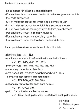
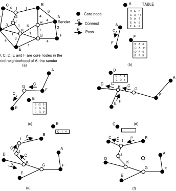
4.1 Activities at the Network and the Overlay layers and the information flow between them . . . 38 4.2 Request zone calculation restricts the propagation of join discovery messages 43 4.3 The Unicast Trap algorithm . . . 44 4.4 Information maintained at the core nodes . . . 54 4.5 Incremental Steiner tree construction by the NAMO NAMAHA forwarding
protocol using primary routers and secondary routers . . . 55
4.6 Distributed Steiner tree construction for the Forwarding Protocol withJ
Algorithm . . . 56
4.7 Steiner tree calculation with partial information - A need to adoptJ 57
5.1 Core Broadcast has aK8MLONPLO message overhead . . . 62
5.2 Memory complexity of core node tables . . . 64 5.3 The edge between the two locally constructed Steiner trees . . . 70 5.4 The time and memory complexities for all the algorithms and data
Chapter 1
Introduction and Related Work
1.1 Mobile Ad Hoc Network (MANET)
These benefits however do not come for free. Due to the mobile nature of the nodes par-ticipating in the ad hoc networks, all the problems addressed and solved in wired networks will have to be revisited. Especially the problem of routing becomes very complicated. One side of the problem is that with the nodes moving randomly, the links can break anytime; the network may get partitioned anytime. The other side of the problem arises due to the low computational capabilities of the participating devices and scarce network bandwidth. Due to the mobility, a healthy percentage of traffic will be control overhead; in propagating the link and routing table information to the network members and these consume a good chunk of bandwidth. Scalability is another major problem. Routing schemes that perform very well with fewer nodes cripple the network if the number of nodes increase. These aspects make MANETs a very challenging area for research. Nevertheless the benefits far outweigh the challenges which make the idea of MANETs worth pursuing.
1.2 Multicasting in MANET and Related Work
One look at the type of applications for which MANETs are used, like classroom confer-encing, military battlefields, disaster relief operations, city vehicular networks, convinces anyone that the applications are inherently collaborative in nature. More often than not, the form of communication in MANETs is group communication. Groups will be formed among the participating members that may communicate with each other to accomplish a particular task. Group communication easily surpasses communication between individual nodes because of this collaborative nature. Clearly the participating nodes need what is called as the6PG;A1E-/
+0*1E-&
7 ability. Multicasting enables one to many communication or in
multicasting service in conventional wired networks. There exists a large amount of litera-ture on multicast in wired and infrastruclitera-ture wireless networks. [GCA02] gives a detailed insight into them. These protocols having been designed for fixed networks, may fail to keep up with node movements and frequent topology changes in MANET. As nodes be-come increasingly mobile, these protocols need to evolve to provide efficient service in the new environment. Therefore adopting the existing wired multicast protocols to MANETS that completely lack infrastructure, appears less promising. [dMCGA03] reviews the ex-isting multicast routing protocols for MANETs which can be easily classified into four categories based on how routes are created to the members of the group:
Q
Tree-based approaches
Q
Mesh-based approaches
Q
Stateless multicast
Q
Hybrid approaches
We briefly inspect the protocols in each of this classification.
1.2.1 Tree Based Approaches
Tree based multicast is a very well established concept in wired networks. Most schemes for providing multicast in wired networks are either source- or shared-tree based.
MAODV routing protocol [RP99] follows directly from unicast AODV, and discovers multicast routes on demand using a broadcast route discovery mechanism employing the same route request (RREQ) and route reply (RREP) messages that exist in the unicast AODV protocol. A mobile node originates an RREQ message when it wishes to join a multicast group, or has data to send to a multicast group but does not have a route to that group. Only a member of the desired multicast group may respond to a join RREQ. If the RREQ is not a join request, any node with a fresh enough route (based on group sequence number) to the multicast group may respond. If an intermediate node receives a join RREQ for a multicast group of which it is not a member, or it receives a RREQ and does not have a route to that group, it rebroadcasts the RREQ to its neighbors.
The LAM [JC98] protocol draws on the Core-Based Tree (CBT) algorithm [GCA02] and Temporal Ordering Routing Algorithm (TORA) in order to provide multicast services. Similar to CBT, it builds a group-shared multicast routing tree for each multicast group centered at the CORE. Nodes in LAM maintain two variables, POTENTIAL-PARENT and PARENT, and two lists, POTENTIAL-CHILD-LIST and CHILD LIST. The PARENT variable is used to remember the parent node in the multicast tree. The CHILD-LIST stores identities of one-hop children in the multicasting tree. The potential data objects are used when the nodes are in a “join” or “rejoin” waiting state.
1.2.2 Mesh Based Approaches
be delivered to the receivers even if links fail.
ODMRP [LSG02] is a mesh based protocol that uses a forwarding group concept (only a subset of nodes forwards the multicast packets). A soft state approach is taken in ODMRP to maintain multicast group members. No explicit control message is required to leave the group. In ODMRP group membership and multicast routes are established and updated by the source on demand. When a multicast source has packets to send, but no route to the multicast group, it broadcasts a Query control packet to the entire network. This Join-Query control packet is periodically broadcast to refresh the membership information and updates routes. When an intermediate node receives the Join-Query packet, it stores the source ID and sequence number in its message cache to detect any potential duplicate. The routing table is updated with an appropriate node ID (i.e., backward learning) from which the message has been received. If the message is not a duplicate and the TTL is greater than zero, it is rebroadcast.
FGMP [CGZ98] can be viewed as flooding with “limited scope”, wherein the flooding is contained within selected forwarding group (FG) nodes. FGMP makes innovative use of flags and an associated timer to forward multicast packets. When the forwarding flag is set, each node in FG forwards data packets belonging to a group G until the timer expires. When a packet is forwarded, only the nodes with an enabled forwarding flag can accept the packet. This soft state approach of using a timer works well in dynamically changing environments. FGMP uses two approaches to elect and maintain FG of forwarding nodes: FGMP-RA (receiver advertising) and FGMP-SA (sender advertising)
1.2.3 Hybrid Approach
The tree based approaches provide high data forwarding efficiency at the expense of low robustness, whereas mesh based approaches provide better robustness (link failure may not trigger a reconfiguration) at the expense of higher forwarding overhead and increased network load. Thus, there is a possibility that a hybrid multicasting solution may achieve better performance by combining the advantages of both approaches.
time to live (TTL) to discover other members. When a core receives a JOIN REQ from a core in a different mesh for the same group, it replies with JOIN ACK. A new bidirec-tional tunnel is created between the two cores, and one of them is selected as a core after the mesh merger. Once the mesh has been established, the core initiates the tree creation process. The core sends out periodic TREE CREATE messages along all links incident on its mesh. Using unicast tunnels, the TREE CREATE messages are sent only to group members. Group members receiving nonduplicate TREE CREATE message forwards it to all mesh links except the incoming one, and marks the incoming and the outgoing links as tree links. If a link is not going to be used as part of the tree, the TREE CREATE is discarded and TREE CREATE NAK is sent back to incoming links. A member node that wants to leave a group can do so by sending a JOIN NAK message to its neighbor nodes.
MCEDAR [SSB99b] is a multicast extension to CEDAR [SSB99a] architecture. The main idea of MCEDAR is to incorporate the efficiency of tree-based forwarding protocols and robustness of mesh based protocols by combining the two approaches. It decouples the control infrastructure from the actual data forwarding. It uses the mesh as the under-lying infrastructure, so it can tolerate a few link breakages without reconfiguration of the infrastructure. The efficiency is achieved by using a forwarding mechanism on the mesh that creates an implicit route-based forwarding tree. This ensures that the packets need to travel only the minimum distance in the tree. More about this will be detailed in Chapter 3 and Chapter 5
1.2.4 Stateless Multicast
the effect of such a problem, stateless multicasting is proposed wherein a source explicitly mentions the list of destinations in the packet header. Stateless multicast assumes small group multicasting.
DDM [JC01] protocol is meant for small multicasting groups operating in dynamic networks of any size. Unlike other MANET routing protocols, DDM lets the source control multicast group membership. The source encodes multicast receiver addresses in multicast data packets using a special DDM data header. This variable length destination list is placed in the packet headers, resulting in packets being self routed towards their destinations using the underlying unicast routing protocol. It eliminates maintaining per-session multicast forwarding states at intermediate nodes and thus is easily scalable with respect to number of sessions.
1.3 Motivation for our Work in the Background of
Re-lated Work
In the previous section we saw how multicast routing protocols fall into the four categories. We can also categorize the multicast protocols based on which layer they operate in. Multi-cast protocols can either operate at the networking layer or it can operate at the application layer as overlays. All of the protocols listed under the first three categories, Tree based, Mesh based and Hybrid operate in the network layer. The protocols listed under Stateless multicast category usually operates in the application layer. The application layer con-structs what is known as overlay tree/mesh which forms the data distribution backbone. Network layer multicasting though efficient, incur more overhead in terms of control mes-sages and update mesmes-sages exchanged between nodes, owing to frequent topology changes. Overlay multicasting, usually at the application level do not incur much control message or update message overhead since they are stateless (that is they do not maintain state in-formation for each multicast groups) but are not as efficient as network layer multicasting. With this and the previous section in mind, our protocol NAMO NAMAHA is motivated by the following arguments:
Q
AMRIS, MAODV, LAM, ODMRP, CAMP, FGMP and AMRoute, which op-erate at the network layer, cannot assume unbounded number of nodes either in the whole network or in any given multicast group due to the control/update message overhead for each change in the topology. Some of these protocols use flooding of messages for sender discovery and data forwarding. [SSB99a] shows by simulation that flooding probes, which causes repeated broadcasts, is highly unreliable because of the presence of hidden and exposed stations.
Q
application layer, construct overlays. But this construction is not at all aided by the network layer which at any time is better informed about the network topology than the application layer.
Q
The Stateless multicast protocols discussed in the previous section are mainly for small groups and they absolutely do not scale to large groups as they make assumptions such as “all the group members should know the information of every other group members” and ”the addresses of all the group members should be included in the data packet”. Many of the network layer multicast-ing schemes like MAODV, ODMRP, etc. also do not scale to larger networks because of excessive control messages.
Q
Multicasting protocols like AMRoute assume the existence of a unicast rout-ing protocol as an underlay. However it does not make any assumption about the particular kind of protocol. We believe that by tightly coupling the over-lay multicasting protocol with a specific unicast routing protocol, better per-formance can be achieved. NAMO NAMAHA uses CEDAR as the under-lying unicast routing protocol. As we can see in the later chapters, NAMO NAMAHA runs in tandem with, and over CEDAR, which allows us to con-struct optimized trees with linear time approximations. NAMO NAMAHA tries to get the best of overlay layer and network level multicasting approaches. Figure 1.1 makes this point clear.
1.4 Contributions of this Thesis
The thesis makes the following contributions:
Q
Overlay Network
Multicast member
Network Layer Unicast Path
Overlay data distribution graph
The network layer provides the overlay with information that is almost invariant, local and that which incurs constant memory overhead
Figure 1.1: The basic idea of NAMO NAMAHA
with useful data from the network layer, that are almost invariant and local in nature, optimized data distribution graphs can be constructed. The network layer definitely has a ‘better idea’ of the underlying network and overlay al-gorithms incur lesser overhead on the network bandwidth. We are, in a way, trying to get the best of both worlds; network level multicasting and stateless overlay multicasting. The next section summarizes the features of the NAMO NAMAHA protocol.
Q
The protocol NAMO NAMAHA, and its algorithms that implement this idea along with proof of correctness and complexity analysis.
Q
large nubmer of nodes, or function as overlays designed only for small groups.
1.5 The Features of the NAMO NAMAHA protocol
In NAMO NAMAHA, we have achieved the following goals:
Q
NAMO NAMAHA scales to larger networks consisting of large multicast groups. NAMO NAMAHA assumes no bound on either the number of nodes in the network or the number of nodes in any given multicast group. This is made possible since the time and memory complexities of the algorithms and data structures are in the linear order of number of nodes or edges.
Q
NAMO NAMAHA builds close to optimal multicast data distribution trees. This is achieved by the incremental approximate Steiner tree construction al-gorithms.
Q
At any given point of time, a path exists between an arbitrary subscriber and the multicast sender with high probability. This is made possible by the re-dundancy offered by the 5R#(-F6S0B#(TU#9!$GV1%#* and the *C%C "!
&
')0B#(TU#9!$GV1%#* (as
explained in Chapter 4)
Q
1.6 Roadmap for this Thesis
Chapter 2
Small Group Multicast - The Basis for NAMO
NAMAHA
2.1 Motivation for Stateless Multicast
overlays using location information for small group. The heuristics rely on packet encap-sulation. The algorithms target to reduce the overall bandwidth cost of the tree. Packet distribution tree is evaluated in a distributed fashion based on the list of destination nodes encapsulated in the IP packet. By distributed we mean that each node calculates only its outgoing branches to the next level subtrees and is not concerned with the construction of the whole tree.
2.2 Background
2.2.1 Problem Statement
If ad hoc network is modeled as an undirected graph, W X FNZYM[\ , where V is the set
of mobile nodes in the network and E is the set of wireless links between neighboring nodes, then the goal of the small group multicasting scheme is to form an undirected graph
W]^X N;]_Y[`]a such that N;]_bcN is the set of group nodes of a particular multicasting
group and[`] is the set of edges which is actually a unicast route between some two nodes
in N;] ; the parent and the child node of the packet distribution tree. For instance an edge
between node Ned and NRf is the unicast path computed by the underlying unicast protocol
between nodesNed andNRf . The packet distribution tree is rooted at the sender node. Two tree
mechanism. We do not discuss these schemes here as they are not related to our work.
2.2.2 Assumptions
The following assumptions are made by this scheme
Q
The number of nodes in a multicast group is in the order of tens so that includ-ing the node address of all the members of such a multicast group in the IP packet would not incur much overhead. The scheme requires that the sender node include the IP address of each node that it knows is in the multicast group to which it is sending data.
Q
Every member in the multicast group knows about the presence of other mem-bers in the same multicast group. Since the number of nodes involved in each multicast group is small, this assumption is justifiable. The members of the multicasting group are aware of the IP addresses of every other member in that group.
Q
The underlying unicast routing protocol is able to forward packets from source to destination along or close to the shortest path. The overlay algorithms as-sume the existence of a unicast routing protocol at the network layer.
Q
Each node in any given multicast group knows almost up to date location infor-mation about other nodes in its multicast group. Each node has some mecha-nism, like GPS, to know its own position with respect to some reference point.
Q
number of network hops.
2.3 Location-Guided K-ary (LGK) Tree Construction
Al-gorithm
This is a greedy heuristic which tries to minimize the overall cost of the tree at each step in the algorithm. The sender first includes the IP addresses of all the receivers of its multicast group in the header of the data packet. The sender then forwards a copy of the packet
to the nearest g nodes. Since each of the node knows the location information of every
other node in its multicast group, the sender can determine which g nodes are nearest to
the sender. Once this is done the sender distributes the remaining nodes in the multicast group apart from its g children, to each of its g children based on geometric proximity.
After this point, the algorithm is repeated recursively at each of itsg children. Each child
will forward the data packet to g more nodes that are closest to it. At each node the first
step is ‘children selection’ and the second step is ‘subtree clustering’. The recursion stops when an incoming packet at some node has an empty destination list. This heuristic uses the approximation relating geometric proximity and number of network hops
In the following example taken from [CN02], binary tree (k=2) is constructed. Figure 2.1 shows the working of the LGK algorithm. Only the participating nodes &ih
, &
d , . . . , &kj
are shown in the figure. The tree is rooted at&ah
since that is the sender. Node&eh
has l
&
d ,
&
f , &km
, . . . ,&kj3n
as its destination list. Based on the list, the LGK tree algorithm runs in two consecutive steps: 1) children selection and 2) subtree clustering. In the first step, the algorithm selects two geometrically nearest nodes as the source node’s children. In the example, node&km
and&ko
are selected because they are the nearest two nodes to&ah
the algorithm goes through the rest of the destinations: if a destination is geometrically closer to&km
, it is put into a sub-list designated as the destination list for&pm
; otherwise, it is put into the destination list for&eo
. This ensures that later on, node&am
and&ko
will find their destinations close to themselves. In the example, the list for &pm
is l
&
d , &kq
, &Ir`n
, and the list for&ko
is l & f , &Is ,&kt , &kjun
. When a destination has equal distances to both&pm
and&ko
, it is taken by the node with a shorter destination list to achieve better tree balancing. The algorithm is repeated recursively at&am
and&ko . n0 (sender) n5 n4 n2 n9 n6 n1 n3 n7 n8
Figure 2.1: The :@-FA<'B#9%
&
*C%CA %C D1E-F!
&
and *GIH1E#9%C%v
"AGI*1%#9-&
7 in Location Guided K-ary
(LGK) tree construction algorithm
reach. Therefore, the sender should include only the active nodes as the packet’s destination nodes. This requires that each node periodically refreshes the membership of itself to the rest of the group. A location update message not only updates a node’s new location, but also refreshes its group membership. If an update message has not been received over a timeout period from a node, the node is purged from the destination list of other nodes. Because of the periodic membership refreshment, the destination nodes are very likely to be reachable from the source node.
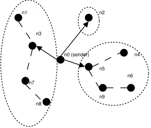
To summarize, LGK tree construction algorithm produces a k-ary tree rooted at the sender with the group nodes as tree nodes. Packets are forwarded node-by-node along the k-ary tree from the source to the rest of the multicast group via unicast routing. This packet forwarding process is guaranteed loop-less because a destination address will be taken out of the list whenever the packet has reached the destination, therefore, it cannot go back to that node again.
2.4 Location Guided Steiner (LGS) Tree Construction
Al-gorithm
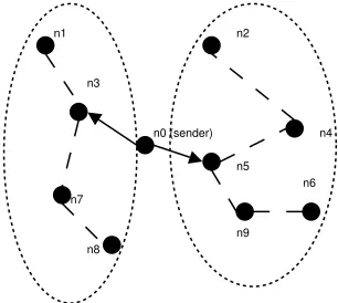
hops. This tree construction process is repeated until all destinations are included in the tree. In a router-assisted multicasting approach, every node in a network can become a tree node to forward packets, in which case the constructed Steiner tree is near optimal. The location-guided Steiner (LGS) tree in [CN02] is constructed using a modified version of the Takahashi-Matsuyama heuristic. The differences are: 1) geometric distance is used as a measurement of closeness; 2) only the group nodes can be used as tree nodes. Between the group nodes, data packets are encapsulated in unicast packets and forwarded via the under-lying unicast routing protocol. Below, the same set of nodes used in the earlier example to illustrate LGK algorithm are used to illustrate the construction of a LGS tree, as shown in Figure 2.2. Again this example is taken from [CN02]. Initially, the tree only contains the sender node&kh
. Within the remaining set of nodes w
&
d ,
&
f , . . . , &ejx
, node&em
is geometri-cally closest to&kh
. Therefore,&km
is added into the tree with edge &ehM&km
. In the second step, the remaining set of unconnected nodes are examined and the node closest to the partially constructed tree is selected. In the example, we compare the distance from&ih
to each of the nodes in the un-connected set w
&
d,
&
f , &Is
, . . . , &kjx
, as well as the distance from&em
to that set, and select the shortest distance which is between&ah
and &Io
. Therefore, &eo
is added to the tree with edge&ehM&ko
. This process repeats until all the nodes have been included in the tree as shown in the figure. Subsequently, the sender node&ph
forwards a copy of the data packet to each of its children nodes, i.e. &
f , &km
, and &ko
, with their corresponding subtrees as destinations. Similar to the LGK tree construction process, the children nodes should be reachable most of the times as result of the periodic membership refreshments. At each of the children nodes, a LGS tree is computed again to further forward the packet. This forwarding process repeats until the packet has reached all members of the group.
n0 (sender)
n5
n4 n2
n9
n6 n1
n3
n7
n8
Figure 2.2: The Location Guided Steiner (LGS) tree construction algorithm
2.5 Extending the Small Group Multicast Scheme to Larger
Groups: The Basic Idea for NAMO NAMAHA
The Small group multicast scheme performs very well for multicast groups having nodes in order of tens. But when it comes to large groups with number of nodes in the order of hundreds or thousands, the same scheme cannot be used; it calls for a whole new approach. There are some assumptions that [CN02] makes which are not feasible for large group multicasting. In this thesis, we attempted to extend this scheme to large group multicasting and came up with the whole new concept in NAMO NAMAHA.
Q
The small group multicast scheme assumes that the sender knows the group members and its identification in advance. This allows the sender to encapsu-late the IP address of all the senders in the packet it sends out to the multicast group. This does not scale if there are large number of subscribers to a mul-ticast group. The sender cannot afford to include the IP addresses of all the receivers when it sends out the data. This assumption has to be removed.
Q
There is no explicit join and leave protocol in [CN02]. The group membership is static and known to the sender in advance. When the group membership is dynamic, we need to have some join and leave protocol. In this thesis, we outline the join and leave protocol that is scalable with the number of network nodes. The join protocol in NAMO NAMAHA will have non-propagating sender discovery unlike that of MCEDAR.
Q
For groups in order or tens this is trivial. But this means tremendous overhead for larger groups. This assumption has to be removed.
Q
[CN02] assumes that the location information about each node is known to all other nodes. The scheme adopts a hybrid location update scheme which at-tempts to keep the location information of all the participating members at any node up to date. The hybrid location update scheme performs poorly for large groups. Once again, this assumption has to be removed. In NAMO NAMAHA we require that the nodes know its location and the sender’s location. But we do not need a location update mechanism since there is no requirement for the nodes to know each other’s location.
Chapter 3
CEDAR: QoS Routing Protocol for Ad Hoc
Networks - The Unicast Underlay for NAMO
NAMAHA
3.1 Logic for having a Specific Unicast Routing Protocol
(CEDAR) as an underlay for NAMO NAMAHA
useful information should be gleaned from local topology knowledge and should be almost invariant. The performance of multicasting overlays, on a large degree, is dependent on the performance of the underlying unicast routing protocol. The search for such a unicast routing protocol led to CEDAR [SSB99a]: Core Extracted Distributed Ad Hoc Routing Algorithm, which is detailed in this chapter along with the justification for the choice.
3.2 Introduction to CEDAR
CEDAR, which stands for Core-Extraction Distributed Ad hoc Routing algorithm, is mainly a Quality of Service routing protocol for ad hoc networks. Here route computation is on demand using only the local state kept track by a set of nodes called the core nodes. There are three components to CEDAR [SSB99a]
Q
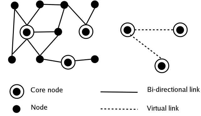
Core Extraction: A set of nodes is dynamically elected in a distributed fashion to form the core of the network by approximating a minimum dominating set (MDS) of the ad hoc network using only local computation and local state. Each core node maintains the local topology of the nodes in its domain and also performs the route computation on behalf of these nodes. The members of the core (approximate MDS) are known as ‘core nodes’. The region up to the third neighborhood of a given core node is known as its ‘domain’. By the property of MDS, each node is either in the MDS or is a first neighbor to a core node in the MDS. For a node that is not in the core, some core node that is its first neighbor will act as its ‘dominator’. This choice is made by the Core Computation algorithm which is detailed later.
Q
far away in the network, while information about dynamic links or low band-width links is kept local. Slow moving ‘increase waves’ and fast moving ‘de-crease waves’, which denote corresponding changes in available bandwidths on links, are used to propagate non-local information over core nodes. In our thesis, we do not focus on this module of the CEDAR protocol.
Q
Route Computation: Route computation first establishes a core-path from the dominator of the source to the dominator of the destination. The core path provides the directionality of the route from the source to the destination. Us-ing this directional information, CEDAR iteratively tries to find a partial route from the source to the domain of the furthest possible node in the core path satisfying the requested bandwidth, using only local information. This furthest possible core node becomes then becomes the source of next iteration, that is, the route using the core path as a directional aid now has to be calculated from this ‘intermediate’ destination to the actual destination.
In this thesis we are interested in the Core Extraction part of the CEDAR protocol. After briefing the network model and terminologies used in CEDAR, we detail the Core Extraction procedure of this protocol.
3.3 Network Model and Graph Terminology for CEDAR
and NAMO NAMAHA
exposed terminal problem. The data transmission is preceded by control packet handoff and the sequence of packets exchanged in a communication is the following: RTS (Request to Send from the sender to receiver) - CTS (Clear to Send from receiver to Sender) - Data (from sender to receiver) - Ack (from receiver to sender)
Ad hoc network is represented by means of an undirected graph WyXzNYM[{ where N
is the set of nodes in the graph (host in the network) and[ is the set of edges in the graph
(links in the network). The-F|}`')%CA<%1%C'
&
%-<7@:RHD!$#~:R!(!9' ,
I of node is the set of nodes
whose distance from is not greater than - except node itself. The -?|} neighborhood
I of node is
IaUwC
x
A dominating set3bcN is a set such that every node inN is either in or is a neighbor of
a node in . A dominating set with minimum cardinality is called a minimum dominating
set (MDS). A
)-F#$1EGI0)AVA-&
g8 OGpYB between two nodes in the dominating set is a path inW
fromG to .
Figure 3.1: Core nodes and the Approximate Minimum Dominating Set (MDS)
Given an MDS N; of a graph W , we define a core of the graph zXNk_YM[4a , where
[4Xw GpYBJLGppN;YV_NV_YGpi
m
<
x
and a set of virtual links between every two nodes inNe that are within a distance 3 of each
other inW . Two nodesG and which have a virtual link GpYB in the core are said to be the
&
%C0B#9HMT nodes
In the CEDAR algorithm, each node picks up a node ind Gk as its dominator (based
on the criteria discussed in the next section), denoted as')!(6U Gk . ')!$6U<GI is the node which
is then called a core node.
3.4 Generation and Maintenance of the Core in CEDAR
The generation and maintenance of core is of primary interest to us and its computation as detailed in [SSB99a] is given here. Consider a node G with first deleted neighborhood
d
GI , degree'I GIZXyL
d
GI$L, dominator')!(6U GI , and effective degree'<GI, where'$ Gk
is the number of its neighbors who have chosenG as their dominator. The core computation
algorithm works as follows at nodeG .
1. Periodically, G broadcasts a beacon which contains the following information
per-taining to the core computation: GiY'<GIDYM';<GI+YM')!$6U<GI
2. IfG does not have a dominator, then it sets'!$6U<GIJ , where is the node in8d Gk
with the largest value for 'C<DYM';< , in lexicographic order. Note that G may
choose itself as the dominator.
3. G then sends a unicast message including the following information:
GiY"w<{Y'!$6U<cCLI{k
d
GI
x
. then increments'
4. If' <GI n
, thenG joins the core.
id. The above algorithm for core computation results in a core which has the following properties.
Q
Since the core computation algorithm approximates the minimum dominating set for the nodes, the size of the core is minimal. As the route computation is done by the core nodes, minimizing the number of core nodes is desirable.
Q
Core computation is local. This property makes core computation in CEDAR scalable as the core can be computed in a constant amount of time.
Q
When a node is electing a dominator, it gives preference to core nodes already present in its neighborhood (including itself). This provides stability to the core computation algorithm, though it might have implications on the optimality of the number of core nodes.
When a node G joins the core, it issues a piggybacked broadcast in
m
<GI . A
pig-gybacked broadcast is accomplished as follows. In its beacon, G transmits a message:
<GpYMK\YMYF5V0~1J: 1E#0B%#*$%C'
&
G;A<A< . DOM denotes the-F' ofGV* dominator. When node hears a beacon that contains a message <GpYM8K{Y-Y5V0~1J: 1E#90B%#~*C%C', it piggybacks the
message <GpYM8K{Y-Z~YF5R0B1J: 1E#90)%#*C%C' ¡ in its own beacon if - nz
. Thus, the piggybacked broadcast of a core node advertises its presence in its third neighbor-hood. This guarantees that each core node identifies its nearby core nodes, and can set up virtual links to these nodes using the5V0~1J: 1E#0B%#~*C%C' field in the broadcast messages.
The state that is contained in a core node G is the following: its nearby core nodes (i.e.
the core nodes in
m
Gk );
<GI , the nodes that it dominates; for each node ;i
Gk , I=i
d
<DY$<=YM')!(6U ¡J . Thus each core node has enough local topology information
the presence of network dynamics is simple. Consider that due to mobility, a node loses connectivity with its dominator. After listening to beacons from its neighbors, the node either finds a core neighbor which it now nominates as its dominator, or nominates one of its neighbors to join the core, or itself joins the core. If a node loses connectivity with all its dominated nodes, or discovers (by monitoring the beacons of its dominated nodes) that its effective degree has become 0, it leaves the core by tearing down virtual links with its neighbors, and finds a dominator in the core.
3.5 Core Broadcasting Mechanism
In order to achieve efficient core broadcast, the scheme assumes that each node tem-porarily caches every RTS and CTS packet that it hears on the channel for core broadcast packets only. The purpose of caching RTS/CTS is to use them for the elimination of dupli-cate packet reception for broadcasts. Since RTS/CTS packets are much smaller compared to the data packets and the core broadcasts would typically arrive from the neighbors in a small period of time, the caching of RTS/CTS packets (only for core broadcasts) for a few seconds is justified. Each core broadcast message that is transmitted to a core node has
the unique tag FY-? . This tag is put in the RTS and CTS packets of the core broadcast
packet, and is cached for a short period of time by any node that receives (or overhears)
these packets on the channel. Consider that a core node G has heard a¡2¢4Y on the
channel. Then, it estimates that its nearby node has received M, and does not forward
to node . Essentially, the idea is to monitor the RTS and CTS packets in the channel in
or-der to discover when the intended receiver of a core broadcast packet has already received the packet from another node, and suppress the duplicate transmission of this packet.
3.6 Advantages of Choosing CEDAR as an Underlay for
NAMO NAMAHA
As it becomes evident in the next chapter, when NAMO NAMAHA uses CEDAR, the following advantages are identified for choosing CEDAR as an underlay unicast routing protocol:
Q
CEDAR uses only local computations and the time complexity of all the algo-rithms involved in CEDAR are linear with number of nodes in the network or number of edges in the network.
Q
core nodes in the third neighborhood, the memory complexity is also constant. We assume a constant bound on the number of neighbors a node can have. See Chapter 5 for complexity analysis.
Q
Core broadcasting hasK8DLNSL message complexity.
Q
The core nodes can provide useful information about the local topology for the application layer to construct efficient overlays. The useful information in-cludes the local link characteristics like delay information, number of network hops local and local topology graph which would aid NAMO NAMAHA to incrementally build the Steiner tree over a subgraph of the core graph which is actually an approximate minimum dominating set.
Q
NAMO NAMAHA uses the CEDAR unicast routing algorithm in its .
&
-/ +0*1 24#90C5 algorithm. In NAMO NAMAHA, we use the fact that the unicast path
between the subscriber and the sender is approximately the best path for the sender to route its multicast data packets to the subscriber.
3.7 MCEDAR: Multicasting Extension to CEDAR
is called the687#90C5V: for the multicast group. Once the 687#90C5V: is extracted for a
multi-cast group, data forwarding is done on the 687#90C5V: using the core broadcast mechanism.
MCEDAR thus has four key components: (i) the 687#05;: which is the multicast routing
infrastructure, (ii) the join protocol, (iii) the core broadcast based on forwarding protocol and (iv) the leaving, pruning and reconstruction protocols. The rest of this section describes in more detail each of these components.
3.7.1 The
£¥¤p¦;§@¨3©Infrastructure
MCEDAR uses a mesh structure called the687#905;: as its multicast routing infrastructure.
The inherent redundancy present in meshes increase the robustness of the687#90C5V: . Hence
recomputation of the 687#90C5V: may not be necessary for every link breakage. This is a
property that is critical to ad hoc environments where link breakages occur often due to node mobility. However unlike other mesh based approaches [], MCEDAR minimizes the
number of nodes in the 687#905;: by requiring only the core nodes to become the member
of 687#905;: . Specifically, an 687#90C5V: is a subgraph of the core graph and not a subgraph
of the underlying network. Thus, only core nodes can become members of an 687#905;: .
When a node wants to become a member of multicast group, it requests its dominating core node to join the appropriate 687#905;: and the dominator then performs the join operation.
3.7.2 The Join Protocol
Since the687#905;: consists of only core nodes, only a core node is allowed to perform a join
operation in MCEDAR. When a non-core node wants to become a member of a multicast group it requests its dominating core node to perform the join operation. A core node performs the join operation by core broadcasting a
,!$-&
#9%ª9G;%$*1¢«eK=¬{Y?,)!$-&
8 .
The join request consists of the address of the group the node wishes to join and the current joinID of the node, corresponding to the multicast group. The joinID of a freshly joining node is set to infinity. When a node that is not a member of MA receives the join request, it forwards the message to its nearby core nodes in accordance with the core broadcast mechanism. On the other hand, when an existing member of MA receives the join request,
it sends a «eK=
¢=®¯{Y?,)!$-&
8 only if its joinID is lesser than the joinID that
arrives in the request. It then forwards the JOIN request further down. However if its joinID is greater than the incoming joinID, it forwards the request like a non-member. Ties in joinIDs are broken based on nodeIDs.
The joinID in the JOIN ACK message back to the node requesting the join is that of the replying node. When an intermediate node on the reverse path (from the replier to the requester) receives the JOIN ACK message, it decides on whether to accept the JOIN ACK or reject it based on the number of JOIN ACKs it has already accepted for the particular multicast group. The member, on accepting a JOIN ACK, sets its joinID to the maximum of its current joinID and the arriving joinID incremented by one. It then stamps the joinID
of the JOIN ACK with its new joinID. Each 687#905;: member maintains two other data
structures, the5V0B#9%
&
1 set and the :@-FA<' set. When a node accepts a JOIN ACK, it adds the
upstream687#905;: member to its parent set. Further, if the downstream node (as specified in
node decides to reject a JOIN ACK, it suppresses the JOIN ACK and does an explicit leave from the upstream node so that its ID is removed from the upstream node’s child set.
3.7.3 The Forwarding Protocol
Although the687#905;: for a multicast group is a mesh infrastructure, the forwarding of data
on the infrastructure is done only on a source based tree, thus saving on redundant trans-missions leading to the efficient usage of the scarce bandwidth. The forwarding protocol of MCEDAR uses the core broadcast mechanism. Specifically, when a data packet arrives at an687#90C5V: member, the member attempts to forward the data packet only to those nearby
core nodes that it knows are also member of the same 687#05;: . Further, some of these
attempts are suppressed by core broadcast mechanism if it is found that a downstream member has already received the same data through a different path. Such a forwarding protocol has two key advantages: (i) it eliminates redundant transmissions and hence saves bandwidth usage and (ii) it implicitly creates a source based tree that represents the fastest delivery structure, for each data packet of the multicast group.
3.7.4 The Leaving and Pruning Protocol
A member of the 687#905;: issues a A<%C0B% message to each of its parents when it does not
have any local members in its domain and its child list is empty. Since all member of the
687#05;: perform the leave operation if the two conditions are satisfied, the mesh is
auto-matically pruned. A parent that receives the leave message from one of its children deletes the corresponding child’s ID from its child set. When a node loses connectivity with all of its parents, then there is a potential partition of the687#90C5V: . In such an event, the node
join). Since only members that have lesser joinIDs respond to this request, the formation of partitions in the687#905;: when the underlying graph is connected is eliminated.
3.7.5 Shortcomings of MCEDAR Answered in NAMO NAMAHA
Chapter 4
Algorithms for the NAMO NAMAHA Protocol
4.1 Introduction
We start with a brief overview of the NAMO NAMAHA protocol. The NAMO NAMAHA protocol has three main components: the
,)!(-&
protocol, the
°k!$#9¢0)#9'B-&
7 protocol and the A %C0B% protocol. When a node wants to subscribe to a multicast group, the dominator of
neighborhood region of the core node that initiated the new Steiner tree construction. The process continues until all the subscribers are included in the multicast data distribution tree. We detail each of the three components of the NAMO NAMAHA protocol, along with the tables and timers used, after looking at the assumptions made by this protocol. See Figure 4.1
Core nodes provide local topology information, upto its third neighborhood, to the overlay algorithms.
-Core nodes form the approximate Minimum Dominating Set of the underlying graph
-Core nodes store the local topology information; the information of the core nodes in the region upto its third neighborhood; the information could be number of network hops, delay, bandwidth availability information, etc. -This storage incurs constant memory overhead assuming a constant bound on the number of neighbors a node can have
NETWORK LAYER OVERLAY
-CEDAR unicast routing protocol at the network layer calculates unicast path from the subscriber to the sender. Roughly the reverse path is used to route the packets from the multicast sender to the subscriber - Unicast Trap algorithm -Core nodes and the virtual links between the core nodes form the core graph -A core node consturcts network hops based Steiner tree in the region upto its third neighborhood over this subgraph
-A set of primary routers and secondary routers forms a subgraph of the core graph [primary and secondary routers will be discussed later]
-Various such Steiner trees when joined form the multicast data distribution tree -Multicast data distribution tree is calculated on the fly whenever the multicast sender has some data to send
Figure 4.1: Activities at the Network and the Overlay layers and the information flow between them
4.2 Assumptions
Q
The link characteristics are symmetric; it is same when measured from node A to node B, if node A and node B are neighbors; and neighborhood is a commutative property; that is if node A is the neighbor of node B, then node B is a neighbor of node A.
Q
Each node knows its location with respect to some coordinate using mechanism such as GPS.
Q
Each multicast subscriber knows the address of the sender for the group which it is subscribing to. This assumption is needed for our unique .
&
-F "0*12`#905
algorithm. We may assume that the sender addresses are published along with the multicast addresses.
4.3 Join Protocol Using the Unicast Trap Algorithm
of primary and secondary routers. We then deal with the request zone calcuation and the ‘trapping’ process. All these components collectively form the Unicast Trap algorithm which implement the join protocol in NAMO NAMAHA.
4.3.1 CEDAR QoS Route Computation
Briefly, QoS route computation in CEDAR is on-demand routing algorithm which proceeds as follows: when a source node * seeks to establish a connection to a destination node' , *
provides its dominator node')!$6UF*$ with a F*~YM'RYMH+ tuple, where b is the required bandwidth
for the connection. If ')!(6U*( can compute an admissible available route to ' using its
local state, it responds to * immediately. Otherwise if ')!(6U*( already has the dominator
of ' cached and has a core path established to ')!$6U' , it proceeds with the QoS route
establishment phase. If')!$6UF*$ does not know the location of ' , it first discovers')!(6U<' ,
simultaneously establishes a core path to' , and then initiates the route computation phase.
A core path from* to' results in a path in the core graph from')!(6U*( to')!(6U<' . ')!$6UF*$
then tries to find the shortest widest furthest admissible path along the core path. Based on its local information')!$6UF*$ picks up the farthest reachable domain up to which it knows
an admissible path. It then computes the shortest-widest path to that domain, ending at a node say1 , once again based on local information. Once the path from * to1 is established,
')!(6U1J then uses its local state to find the shortest-widest furthest admissible path to '
along the core path, and so on. Eventually, either an admissible route to' is established, or
4.3.2 The Primary and the Secondary Routers
The dominator of the node that joins the multicast group is marked as a primary router for that multicast group. The unicast path between the subscriber’s dominator and the sender’s dominator is a core path and each core node in this path flags itself as a primary router for the multicast group to which the subscriber just subscribed. All the core nodes in the third neighborhood region of a primary router flag themselves as a secondary router for that multicasting group. A core node becomes a secondary router on receiving the periodic beacon message from some primary router in its third neighborhood.
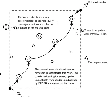
4.3.3 The Request Zone Selection and Multicast Sender Discovery
is restricted to the request zone. The core broadcast messages used in unicasting will have the location of the subscriber and the sender in it. The core nodes receiving these core broadcasting messages will further core broadcast the message only if it finds that it is in the request zone based on the location of the sender and the subscriber. Else it will discard the messages and will not further core broadcast them. Figure 4.2 depicts the idea of the request zone calculation. There is a ‘bootstrapping’ problem that needs to be addressed in the request zone calculation protocol. How will the dominator know the location information of the sender when it sends the unicast for the first time ? If the dominator is also dominating a node which subscribes to the same multicast group, it would have the location information of the sender (location information is included in all the multicast data packets). It will then include this information in the join core broadcast unicast packet. Else the dominator will leave the sender location fields empty hoping that some core nodes in the path that knows the correct location of the sender will enter in the values there. However this approach is still better than the join protocol in MCEDAR.
4.3.4 The Process of Unicast Trapping
When the dominator sends the unicast message it need not necessarily travel all the way from the subscriber to the sender. When a primary router on the unicast path from the subscriber to sender, which is also a dominator for a node subscribing to the same multicast group, gets this unicast message, it traps and terminates the unicast. That node is however subscribing to the same multicast group from the same sender and would have sent a unicast message to the sender. We term this process as
1E#905~5R-&
7 . Figure 4.3 depicts the overall
Subscriber
Multicast sender
The request zone - Multicast sender discovery is restricted to this zone. The core broadcasting for setting up the unicast path from sender to subscriber by CEDAR is restricted to this zone
The request zone The unicast path as calculated by CEDAR This core node discards any
core broadcast sender discovery message from the subscriber as it is outside the request zone
Figure 4.2: Request zone calculation restricts the propagation of join discovery messages
4.4 Tables involved in NAMO NAMAHA and the
Modifi-cations Required for the Beacon Messages in CEDAR
The dominator core node will have to maintain the following:
Q
Multicast membership information for every node it dominates.
Q
Multicast groups for which it acts as a primary router.
Q
The subscriber informs its dominator when it wants to join a multicast group, say M
Core node which dominates the subscriber This is the first primary router on the path to the multicast sender
The unicast path as calculated by CEDAR from the subscriber to the sender. Approximately the same path will be used for sending data from the sender to the subscriber
The node that dominates the multicast sender. The CEDAR constructs the unicast path of core nodes between the dominators of the sender and subscriber
The core node which will act as a primary router for the multicast group M. This core node is in the unicast path from the sender to the subscriber. If it is already a primary router for ’M’, and also the dominator for the node subscribing to the same multicast group, then the unicast message is trapped and truncated at this point. The region upto the third neighborhood of the primary router
This node becomes the secondary router for multicast group M since it is in the region of third neighborhood of the primary router
Multicast sender
subscriber
Figure 4.3: The Unicast Trap algorithm
A core node exchanges this information with the core nodes in its third neighborhood. This would involve the modification of the beacon messages used in the CEDAR protocol.
In CEDAR, When a nodeG joins the core , it periodically issues a piggybacked broadcast
in
m
<GI . A piggybacked broadcast is accomplished as follows. In its beacon,G transmits
a message: <GpYM8K{YMYF5R0B1J: 1E#90B%#~*C%C'
&
G;A A< . DOM denotes the-/' of G * dominator.
When node hears a beacon that contains a message GpYM8K\±Y-YF5R0B1J: 1E#90B%#*C%C' , it
piggybacks the message <GpYM8K{Y-~²~YF5V0~1J: 1E#90)%#*C%C'_P¡ in its own beacon if-~
n
. Thus, the piggybacked broadcast of a core node advertises its presence in its third neighborhood. This guarantees that each core node identifies its nearby core nodes, and cet up virtual links to these nodes using the5V0~1J: 1E#0B%#~*C%C' field in the broadcast messages.
nearby nodes and set up virtual links without having the knowledge of the whole core graph.
NAMO NAMAHA requires following changes to the beacon message. Each beacon message should also contain a list of multicast groups for which the beacon originating core node is a primary router and a list of multicast groups for which it is a secondary router. So the new beacon message would be <GpYM8K{Yl³5R#9-6S0B#9T´µ#9!$GV1%#¶µA -/*1
n Yl *C%C "! & ')0B#(T\·#!$GR1%#c¯A-?*1 n YMYF5R0B1J: 1E#90B%#*C%C' &
G;A A< . The5V0~1J: 1E#90B%#*C%C' should be
of the form&
deU Cd<f & f_³ Df m &kmC¸¹¸¹¸
, where&
, is node - and
Oº is the cost for taking the
link between nodes- and, . The receipt of5V0~1J:
|
#90B%#~*C%C' in this format from all the core
nodes in the third neighborhood in effect gives the local topology information for the core node that is receiving the beacon message.
When a beacon message from a core node reaches another core node, if the beacon originating node is a primary router for a multicasting group, then the beacon receiving node flags itself as a secondary router for that multicasting group. Each core node stores the primary router list and the secondary router list for every other core nodes in its third neighborhood. Figure 4.4 shows the table maintained by each of the core node.
4.5 The Timers in NAMO NAMAHA
Following timers are used in NAMO NAMAHA:
Q
6S%6SHD%#*(:@-¹5V»¡%$°I#9%$*(:24-F6S%# : A subscriber should periodically send
mem-bership refresh information to its dominator. Else the dominator will assume that the node is no longer subscribing
Q
5R#(-F6S0B#(T»¡!$GR1%#¼Z-/°k%24-F6S%# : A node will act as a primary router only for the
unicast message from the subscriber to the sender, it ceases to act as primary router
Q
*C%C +!
&
'0B#(T»¡!$GR1%#¼Z-/°k%24-F6S%# : A node ceases to act as a secondary router
for a multicast group if it does not hear a refresh message from some primary router for that multicast group within the time length specified by this timer
Q
G
&
-F "0*1J½%$*$*C0~7%24-6S%# : The dominator of a subscriber should send periodic
unicast messages to the sender based on this timer. The reason for this periodic unicast message is to refresh the trail of primary routers that would be used to route the multicast data packets from the sender to the subscriber. Due to node mobility, primary routers may move away, or the unicast route from the subscriber to the sender might become outdated. However this period should be large enough to justify the advantages of such a join protocol. Each time the unicast message is sent it is not necessary that the message be relayed up to the sender. The unicasting may be truncated midway if it encounters a primary router, which is also a dominator for some subscribing node, on its path to the sender. In the next subsection we outline the guidelines to select the values for
G
&
-F "0*1J½%$*$*C0~7%24-6S%# .
4.5.1 Guidelines for Selecting Optimum Unicast Interval
The period for unicasting from the subscriber to sender is so set that the number of unicast messages is much less compared to the number of multicasting messages sent. And at the same time not too few to disconnect the node from the multicasting tree for a long time. The interval is set based on the following guidelines:
Q
The value ofG
&
-/ +0*1J%$*(*C0~7%24-F6S%# should be inversely proportional to the
smaller unicast interval and relatively less mobile ad hoc networks will have larger unicast intervals.
Q
The value ofG
&
-/ +0*1J%$*(*C0~7%24-F6S%# should be inversely proportional to the
distance of the subscriber from the sender. If the distance of the subscriber from the sender is more, the core path would involve more core nodes and the chance that the path breaks due to some primary router moving out increases. So fresh routes will have to be established more often.
Q
*C%C +!
&
'0B#(T»¡!$GR1%#¼Z-/°k%24-F6S%# should be large enough so that even if the
pri-mary router ceases to exist, the secondary routers can still route packets from the sender to the subscriber in the absence of the primary routers. A new set of primary routers might get created when the subscriber’s dominator sends a unicast message to the sender afterG
&
-F "0*1J½%$*$*C0B7%24-F6S%# .