NUMERICAL SIMULATION OF ROUND ROBIN EXERCISE IRIS-2012
FOR BENDING AND PUNCHING TEST
Sourav Acharya1, Debashis Mukherjee2, Ajai Pisharady1, and L. R. Bishnoi3
1
Scientific Officer, Siting & Structural Engineering Division, Atomic Energy Regulatory Board (AERB), Mumbai, India ([email protected]) ([email protected])
2
Manager, L&T Construction, Mumbai, India
3
Head, Siting & Structural Engineering Division, Atomic Energy Regulatory Board (AERB), Mumbai, India
ABSTRACT
Protection of important reinforced concrete structures like nuclear structures against missile impact either environmentally generated or as a terrorist activity, is one of the topics of discussion in recent days, specifically after the incident of 9/11 in USA. Development of computational capability for assessment of structural integrity against missile impact is under progress around the globe and needs strong cutting edge technological competency as the simulation is highly complex in nature. IRIS-2012 is a round robin exercise to simulate or predict the response of missile and target numerically based on small scale experiments. This includes modeling and nonlinear analysis of a concrete slab, and simulation of missile impact and response of the structure. An attempt has been made in this paper to simulate the flexure test (impact by a soft/deformable missile) and punching test (impact by a hard/rigid missile) on a reinforced concrete slab. ABAQUS/Explicit Code is used for simulation. The analysis is technologically challenging and all the behavioral aspects of the problem cannot be simulated directly because of software limitations. To simulate impact of soft missile, multiple stress-strain property based on different strain rates was successfully introduced and a methodology was developed based on impact mechanics and wave propagation in solid media to simulate local responses of target due to impact of hard missile, such as spalling, scabbing, penetration and perforation.
INTRODUCTION
A round robin exercise (RRE) on ‘Improving the Robustness assessments methodologies for structures Impacted by missileS (IRIS-2012)’ was instituted jointly by IRSN, France and CNSC, Canada based on experiments conducted by VTT, Finland. Outcome of the RRE (1st phase) completed in 2010 was not encouraging. The IRIS-2010 exercise was on blind simulation of impact tests. The RRE (2nd phase) was floated again in the year 2012 to improve the simulation results so as to be close to the experiments. A team from AERB, India also participated in IRIS-2012 (2nd phase) for the first time. The experiments comprised of bending and punching test of reinforced concrete (RCC) slab with soft and hard/rigid missiles respectively. The scope of the exercise was post-test simulation of flexure as well as punching test using experimental data. The main objective of this exercise is to improve capability regarding damage assessment of NPP structure by commercial airplanes crashes. As this type of analysis is extremely complex in nature, experiments as well as simulations had been done using simple structures like RCC slab as target and steel cylinders as missiles, hard/soft.
SIMULATION OF BENDING TEST
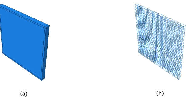
The target was a 2.1m x 2.1m x 0.25m reinforced concrete slab with transverse/shear reinforcements. The target slab was modeled using solid elements, where as individual reinforcing steel including shear links were modeled using truss elements as shown in Figure 1(a), (b). The missile was modeled as shell. Figure 2(a) and (b) show a view of the missile and its assembly with the target before impact. Number of elements across slab thickness plays an important role in capturing the strain rate occurring in the model. Mesh-sensitivity study was conducted and 15 mm was taken as the mesh size so as to provide 10 elements across the slab. Similar element size was adopted for meshing the missile and reinforcing steel. Hourglass control and adaptive meshing option were utilized for numerical stability of the solution procedure.
(a) (b)
Figure 1.(a) Geometric model of RC Slab and (b) Reinforcement
(a) (b)
Figure 2. (a) Geometric model of soft missile and (b) assembly before impact
Material Model: Concrete
given confining pressures to equivalent strain rates, Figure 3(a). IRIS-2012 organisers also supplied cracking stress value for concrete in tension, without details of softening curve or fracture energy value (Gf). Bi-linear stress-displacement curve, proposed by Gylltoft and as reported by Leppanen (2002) was
used for this purpose, which is based on stress-crack opening relationship. Fracture energy (Gf) is
considered as 110 N/m assuming 20 mm as maximum aggregate size, JSCE (2008). The stress-strain curve for static case in tension is derived based on these data. The stress-strain curve of concrete in tension for different strain rates are derived from the static curve, as derived above, using formulation given by Malvar, et al. (1998). Figure 3 (b) shows the derived stress-displacement curve of CDP in tension for multiple strain rates.
(a) (b)
Figure 3. Constitutive relationship of concrete at various strain rates (a) in compression and (b) in tension
Material Model: Steel
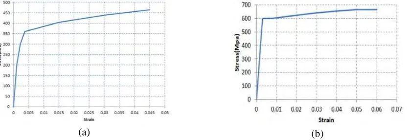
Both reinforcing and carbon steel (missile) were modeled using elastic-plastic stress-strain relations, Martin, O. et al. (2011), Figure 4. Strain rate effects were taken into account in reinforcement steel material model by specifying yield stress ratios, a factor, by which the yield strength of material increases with given strain rate; 1.43, 1.46 and 1.49 for 100, 250 and 600 s-1 strain rates respectively.
(a) (b)
Figure 4. Constitutive relationship of steel used in (a) missile and (b) reinforcing bars
Literature on impact of soft missile reveals that supporting frame is sufficiently rigid to prevent large rigid body displacement of the test slab and may be neglected in modeling, Saarenheimo et al. (2011). Out of plane restraint was applied on both front and rear faces along all four edges at 50 mm inside the slab edge to simulate simple support condition. Initial position of the missile was a point contact with the target plate at center and velocity of 110 m/s was applied as a predefined field for simulation. The analysis was conducted using ABAQUS/Explicit technique for a duration of 100ms and output was extracted at 0.25ms interval. The stable time increment, observed throughout the analysis, was of the order of 1.12E-6 s or 1.12µs.
SIMULATION OF PUNCHING TEST
Finite Element Model
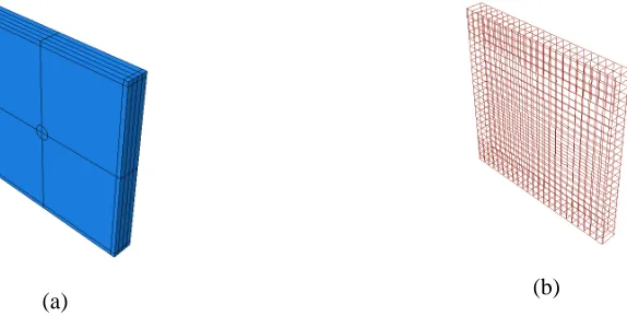
The target was a 2.1m x 2.1m x 0.25m reinforced concrete slab without transverse/shear reinforcements. The target slab was modeled with solid elements, where as individual reinforcing steel was modeled using truss elements, Figure 5(a), (b). In case of rigid missile, the outer shell layer (made of steel) as well as filled light weight concrete was modeled using solid elements. Figure 6(a), (b) show the sectional view of outer steel layer 6(a) and light weight concrete 6(b) respectively. An aluminum pipe, which was attached as tail of the missile to trace the missile residual velocities in the experiment, was not modeled in simulation for simplicity.
(a) (b)
Figure 5. Geometric model of target, (a) concrete and (b) reinforcements
(a) (b)
Material Model: Concrete
Concrete models available in ABAQUS/Explicit are concrete damage plasticity model (CDP), smeared crack model and brittle crack model. However, except brittle crack model, other constitutive models of concrete do not have the capability to simulate ‘element erosion’, ABAQUS-6.10(2010). In case of brittle model, the compressive behavior is always assumed to be elastic. Modeling of ‘element erosion’ is necessary for simulating penetration, perforation, spalling and scabbing of target in case of punching test. So, elastic-plastic constitutive relation (compression as well as tension) was used for concrete material of the target. Two different failure criteria, such as ‘shear failure strain’ and ‘tensile failure hydrostatic stress (cut-off stress)’ are incorporated in that model to simulate ‘element erosion’ of the target. The reinforcement steel is modeled as elastic-plastic material as per given data with ‘shear failure strain’ criteria. Figure 7 shows the constitutive relationship of concrete slab 7(a) and its reinforcements 7(b).
(a) (b)
Figure 7. Constitutive relationship of (a) target concrete slab and (b) reinforcing steel
Material Model: Missile
Outer steel layer of the missile is modeled as elastic-plastic material without any ‘element erosion’ criteria and the filler concrete is modeled using CDP material with low density (1520 Kg/m3). Figure 8 shows the constitutive relationship of outer steel layer 8(a) and light weight concrete fill 8(b) of rigid missile.
(a) (b)
Numerical Analysis
The target slab is ‘partitioned’ based on its failure criteria due to missile impact. Based on literature on impact mechanics, Polanco-Loria et al. (2008), Tuomala et al. (2011) and Walley et al. (2005), it is understood that thickness near to impact zone of target undergoes inertial compaction, whereas at other side or back side of target experiences tensile stress and creates scabbing. The compressive shock wave returns/reflects from back faces and converts into tensile shock wave and creates spalling at front face. So, it is assumed that 1/4th thickness of the target slab near impact zone fails in shear (simulate penetration) and remaining areas of target fail in hydrostatic tensile stress (simulate perforation) or cut-off stress. The ‘shear failure’ zone is cylindrical with diameter nearly equal to missile diameter and the length is equal to 1/4th thickness of the slab. The concrete at boundary zone (50 mm from edge) is assumed to be elastic without any failure to ascertain numerical stability of the analysis preventing ‘element erosion’ at support locations.
The ‘shear failure’ of reinforcement steel is assumed at uniaxial strain of 18% (uniaxial failure strain of this steel is 20% as per supplied test data). The uniaxial tensile stress of target concrete is 4 MPa, where as supplied experimental data shows an enhancement of this tensile stress nearly to 20 MPa under high ‘strain rate’ of 200 s-1. Thus, cut-off stress of concrete target is considered as 20 MPa. Simulations are done considering various values of ‘shear failure’ of concrete of target slab. A ‘shear failure’ strain value of 18% produces a good match of trail velocity with experiments and other responses of target and missile.
The supporting frame is not modeled. The target is simply supported at four sides of front as well as back faces, 50 mm inside the edges. The target is also simply supported at bottom, mid thickness line. The movement of missile is allowed only in perpendicular direction of target surface, thus restrained from any rigid body rotation during penetration/perforation. The missile is placed just in contact with target before analysis to simulate the analysis immediately at the impact. The missile velocity of 135 m/s is applied in ‘predefined field’ of initial step. ABAQUS/Explicit Code is used with automatic time steps, where ‘stable time increment’ is 1.4 µs (microsecond). The analysis is simulated for 100ms (millisecond). The responses of missile and target are extracted at an interval of 25 ms and 100 ms respectively.
RESULTS
Bending Tests
(a) (b)
Figure 9. (a) Deformation of missile just after the impact and (b) longitudinal section of deformed missile
(a) (b)
Figure 10.(a) Displacement time history of the missile and (b) Load time history between missile and target
(a) (b)
(a) (b)
Figure 12. Plastic equivalent strains in the slab after the impact (a) front face and (b) across the thickness.
Punching Test
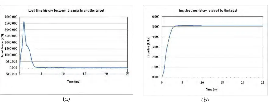
The trail velocity of the missile is found to be 33.4 m/s. The trail velocity of the missile is measured at the time, when the missile has just perforated the target fully (estimated as 2.75 ms). Figure 13 shows the missile velocity 13(a) and displacement 13(b) time histories. The experimentally measured trail velocity of missile was 38.3m/s, which is close to the simulated value.
(a) (b)
Figure 13. Time histories of missile (a) velocity and (b) displacement
(a) (b)
Figure 14. (a) Load time history between missile and target and (b) impulse time history of the slab
(a) (b)
Figure 15. Spalling of target at front face; (a) experiment and (b) simulation (black areas are eroded elements)
(a) (b)
Figure 16. Scabbing of target at back face; (a) experiment and (b) simulation
The following conclusions can be drawn from the simulations:
• Concrete Damage Plasticity model, available in ABAQUS/Explicit, can simulate the flexure test considering multiple stress-strain properties for various strain rates.
• The maximum value of compressive strain in the front end of the slab and the peak value of support reactions for flexure test were in good agreement with the results observed experimentally.
• The free-vibration behavior of the slab, post impact, could not be captured properly resulting in lower recovery of slab displacement.
• The scabbing and spalling behavior during impact of soft missile could not be simulated using CDP model available in ABAQUS/Explicit.
• Zoning of target based on stress wave propagation could simulate local damage responses such as spalling, scabbing during simulation of punching test.
• Penetrations as well as perforation of hard missile during punching test are highly dependent on ‘element erosion’ criteria of different materials given as input to ABAQUS/Explicit.
REFERNCES
ABAQUS-610 (2010). “ABAQUS 6.10 User Documentation - Theory manual”, Dassault Systems Simulia Corp., Providence, RI, USA.
Japan Society of Civil Engineers standards. (2008), JSCE, Standard Specification for Concrete Structures-Design, JGC 15, Japan, 2008.
Leppanen, J. (2002). “Dynamic behavior of concrete structures subject to blast and impact,” Thesis for the degree of Licentiate of Engineering, Department of Structural Engineering, Chalmers University of Technology, Göteborg, Sweden.
Malvar, L. J. and Crawford, J. E. (1998). “Dynamic Increase factor for Concrete,” 28th DDESB Seminar, Orlando, FL.
Martin, O., Centro, V. and Schwoertzig, T. (2011). “Numerical Analyses on the Missile Impact Tests performed at VTT within the Benchmark Project IRIS,” JRC Scientific and Technical Reports, JRC 65180, European Commission, Joint Research Centre, Institute for Energy. http://publications.jrc.ec.europa.eu/repository/bitstream/111111111/22298/1/reqno_jrc65180_ldn a24880enc.pdf.pdf
Polanco-Loria, M., Hopperstad, O. S., Børvik, T. and Berstad, T. (2008). “Numerical Prediction of Ballistic Limits for Concrete Slabs using a Modified Version of the HJC Concrete Model,” International Journal of Impact Engineering, Vol. 35, 290-303.
Saarenheimo, A., Tuomala, M., Vailikangas, P. and Hakola, I. (2011). “Sensitivity Studies on IRIS 2010 Bending Wall” Transactions of International Conference- SMiRT 21, New Delhi, India, Div-V, paper#518.
Tuomala, M., Saarenheimo, A., Calonius, K., Valikangas, P. and Vepsa, A. (2011). “Sensitivity Studies on IRIS 2010 Punching Wall,” Transactions of International Conference- SMiRT 21, New Delhi, India, Div-V, paper#832