Available online:
http://edupediapublications.org/journals/index.php/IJR/
P a g e | 616Fuzzy controlled Three Phase STATCOM for
compensation of Single Phase Loads
B. Naga Babu
M-tech student Scholar
Department of Electrical & Electronics Engineering, Raja Mahendra Engineering College, Ibrahimpatanam;
Ranga Reddy (Dt); Telangana, India. Email: [email protected]
M. Srinivas
Assistant Professor
Department of Electrical & Electronics Engineering, Raja Mahendra Engineering College, Ibrahimpatanam;
Ranga Reddy (Dt); Telangana, India. Email: [email protected]
Abstract- The unbalanced currents caused by single-phase loads that are connected across any two terminals of the three-phase by using STATCOM will compensate the system. Most of these loads consume more reactive power and thus increases feeder losses and reduces active power flow capability of the system.. In this concept, a STATCOM based controller for a three phase system feeding single phase loads is presented. The objectives of the controller in the system is to compensate the inductive loads to obtain nearly unity power factor, balance the source currents by cancelling the effect of unbalanced loads and to filter out the load harmonic currents in order to form a sinusoidal supply current. Single phase synchronous reference frame theory based algorithm is used for generating the reference source currents. The dc-link voltage of STATCOM has been regulated to a reference value under various load conditions. This can be done for single phase linear and non-linear loads under balanced and unbalanced conditions. From the waveforms obtained it is clear that the source current and source voltage are in phase that is, source side power factor is unity. Also it is found that the source currents are become balanced and sinusoidal under the application of the controller. In this PI controller is replaced with fuzzy logic controller to improve the performance of the system. The harmonic content in the source current is reduced by using Fuzzy controller.
Key Words- Single-phase Synchronous D-Q frame theory, static synchronous compensator (STATCOM), Fuzzy Logic Controller
I. Introduction
In remote areas, plenty of non-conventional energy sources are available. These non-conventional energy sources are used as prime input for the generating systems. Distributed power generation has become a topic of interest in recent years to supply power to remote, rural and isolated regions. Need for standby power is also increasing rapidly due to unreliable utility supplies. Heavy distribution losses and investment in transmission lines compel one to seek autonomous power generation. Depletion of fossil fuels has turned our attention towards renewable energy sources. For power generation wind, small hydro and biomass are attractive options. Since they are exceptionally to be located in isolated regions, the technology must be simple, rugged and easy to maintain
and operate. Suitable energy conversion system has to be developed for such applications. On the electrical side the generator and controller have to be appropriately chosen to meet the customer needs. Attempts have been made to maintain constant terminal voltage by fixed capacitor and thyristor controlled inductor (SVC), saturable-core reactor and short-shunt connection, however, voltage regulation provided by these schemes is of discrete type and injects harmonics in the generating system. By the invention of solid-state self commutating devices, it is possible to make a static, noiseless voltage regulator, which can provide continuously variable reactive power to the SEIG with varying load to keep terminal voltage constant. This system called STATCOM has specific benefits compared to SVC has derived governing equations of STATCOM to determine the response of the STATCOM. In this paper, the single phase linear and non-linear loads are connected to the three-phase SEIG which cause unbalance current and draws non-sinusoidal current due to non-linearity of load which injects harmonics into the system. The STATCOM is introduced to eliminate the harmonics, provides load balancing and supplies the reactive power and feeding single-phase loads using a three-phase without de-rating the machine. The transient analysis of the STATCOM system under balanced/ unbalanced single-phase linear and non-linear loads and simulated results show that the STATCOM system behaves an ideal supply under these unbalanced loads.
II. SYSTEM CONFIGURATION A. Block diagram description
Available online:
http://edupediapublications.org/journals/index.php/IJR/
P a g e | 617 Fig.1. Block diagram of the systemThe controller is used for controlling the switching of STATCOM switches. Single phase synchronous reference frame theory based control algorithm is used for generating reference signals. The controller senses source current, load current, source voltage and dc link voltage and used as feedback signals. It uses a PI controller to maintain the dc bus capacitor voltage constant and greater than the peak value of the line voltage of PCC for successful operation of the STATCOM.
B. STATCOM design
The selection of ST ATCOM parameters is very important factor, as it should provide the reactive power required by the loads under different conditions. The STATCOM should be able to carry the reactive current needed by the loads. The coupling filter inductor should be selected on the basis of the reactive power demanded by the loads connected to the system. Current through the STATCOM is given as
(1)
Where Ps is the reactive power required by the load. The filter inductor can be calculated as
(2)
Where f is the switching frequency, icr is the
ripple current, m is the modulation index. k is the current factor corresponding to the transients during load variation. VDC is the dc bus voltage and it should be
greater than PCC voltage for proper operation of the STATCOM.
(3)
Where V is the phase voltage and m is the modulation index. The dc bus capacitor of ST ATCOM should provide the instantaneous energy at sudden loading. It also provides energy instantaneously under transient operation. Energy transferred is,
(4)
Where t is the response time of the ST ATCOM and IS around 250 s to 350 s.
The energy transfer in the capacitor is given as
(5)
Therefore the dc link capacitance is,
(6)
III. CONTROL ALGORITHM
The reference source currents for reactive power compensation and load balancing are generated using single phase synchronous reference frame theory. The single phase signal is transformed to a two phase signal and then converted to rotating frame using the following relationship.
(7)
Available online:
http://edupediapublications.org/journals/index.php/IJR/
P a g e | 618(8)
Transform the voltage and currents of each phase in to stationary a-p frame, then the source voltages in stationary α-β frame are represented as
(9)
(10)
For obtaining unity power factor at source side, the STATCOM provides reactive power as needed by the load. By using single phase synchronous reference frame theory based control algorithm reference source currents are extracted from load current. Reference current includes only the fundamental component of load current. The block diagram of the control algorithm is given in figure 2. The load currents (iLa, iLb, iLc) are sensed and transformed into stationary
α-β frame using a phase shifter. In order to calculate the active power demand of the load, the direct axis component of load current should be calculated. The D-axis component is used for generating reference source current such that unity power factor is maintained at source side. The direct axis components corresponding to load current in each phase is obtained by transforming the signals from α-β frame to synchronously rotating D-Q frame.
Fig.2. Block diagram of control circuit
The direct axis component of A phase is obtained by the following relationship
(11)
Where cosθa and sinθa are calculated using the relations
(12)
That is,
(13)
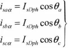
Similarly the direct axis components corresponding to phases B and C are
(14)
(15)
The D-axis components consist of both fundamental and transient part of current from which fundamental is derived using a low pass filter.
Equivalent direct axis component of the system is
(16)
In order to meet the losses in the STATCOM, an additional active power is drawn from the source by which the dc link voltage remains stable at the reference value. The equivalent active power component is obtained by comparing the sensed dc link voltage with a reference value and processing the error using a PI controller. The loss component is added up with the D-axis current. The voltage error is,
Available online:
http://edupediapublications.org/journals/index.php/IJR/
P a g e | 619Where Vdcref is the reference dc link voltage and Vdc is the
sensed dc-link voltage.
D-axis component required is equally distributed among the three phases for maintaining balanced source current and they are converted back into stationary frame using inversa Park's transformation.
(18)
The α-axis component is the actual reference current and β-axis component is the current corresponding to imaginary orthogonal component. Therefore a-axis current is taken as reference source current and compare it with sensed values of each phase. The resulting error signal is used to drive the STATCOM switches using a current controlled PWM generator.
(19)
The current error signals are obtained by comparing the calculated components with sensed load currents and these errors are fed to PWM generators for obtaining the gate pulses for the STATCOM.
(20)
VI. Matlab/Simulink Model
Fig. 3 Simulink Block Diagram
Case 1: Unbalanced non-linear Condition
Fig.4 Source voltage and Source current
Available online:
http://edupediapublications.org/journals/index.php/IJR/
P a g e | 620 Fig.6 Source voltage active and reactive powerFig.7 Source current active and reactive power
Fig.8 Load voltage active and reactive power
Fig.9 Load current active and reactive power
Fig.10 Source voltage THD
Fig.11 Source current THD
Available online:
http://edupediapublications.org/journals/index.php/IJR/
P a g e | 621 Fig.12 Source voltage, dc-link voltage, RMS voltage and source currentin single phase
Fig.13 Source voltage, dc-link voltage, RMS voltage and source current
in single phase 2
Fig.14 Source voltage, dc-link voltage, RMS voltage and source current
in single phase 3
Fig.15 Source current THD
Fig.16 PF angle between source voltage and source current
Case 3: Under balanced non-linear Steady state Condition
Fig.17 Source voltage, dc-link voltage, RMS voltage and Load current
Available online:
http://edupediapublications.org/journals/index.php/IJR/
P a g e | 622 Fig.18 Source voltage, dc-link voltage, RMS voltage and Load currentof single phase 2
Fig.19 Source voltage and line current of single phase 3
Fig.20 Source current THD
Fig.21 Power factor angle between source voltage and source current
Case 3: Under balanced non-linear Transient state Condition
Fig.22 Source voltage and source current of single phase
Fig.23 Source voltage, dc-link voltage, RMS voltage and Load current of single phase 2
Available online:
http://edupediapublications.org/journals/index.php/IJR/
P a g e | 623Fig.25 Source voltage and line current of single phase 3
Fig.26 Source current THD
Fig.27 Power factor angle between source voltage and source current
Case 4: Steady state performance of the system under unbalanced nonlinear load condition:
Fig.28 Source voltage and source current of single phase
Fig.29 Source voltage, dc-link voltage, RMS voltage and Load current
of single phase 2
Available online:
http://edupediapublications.org/journals/index.php/IJR/
P a g e | 624Fig.31 Source voltage and line current of single phase 3
Fig.32 Source current THD
Fig.33 Power factor angle between source voltage and source current
Case 5: Using Fuzzy Logic Controller
Fig.34 Source voltage and source current of single phase
Fig.35 Source voltage and source current Active and reactive power of
single phase
Fig.36 Source voltage, dc-link voltage, RMS voltage and Load current
Available online:
http://edupediapublications.org/journals/index.php/IJR/
P a g e | 625 Fig.38 Source voltage and source current of single phase 1Fig.39 Source voltage and source current of single phase 3
Fig.40 Source current THD
V. Conclusion
The proposed method of feeding single-phase loads from a three-phase STATCOM has been tested, and it has been proved that is able to feed single-phase loads
up to its rated capacity. Hysteresis based Fuzzy controller of a three-phase STATCOM has been proposed, discussed, and experimentally implemented for current balancing of the system. From the simulated results, it is found that terminal voltage remains constant and sinusoidal feeding the three-phase or single-phase rectifiers with Linear and non-linear loads. The proposed FLC based STATCOM have improved the power quality of source current significantly by reducing the THD. It is clearly presented that STATCOM with FLC gives better performance than STATCOM with conventional PI controller. Therefore, it is concluded that STATCOM acts as voltage regulator, load balancer and also harmonic eliminator.
References
[1] Bo˘stjan Bla˘zi˘c, Igor Papi, “Improved D-STATCOM Control for Operation with Unbalanced Currents and Voltages”, IEEE transactions on power delivery, vol. 21, no. 1, January 2006
[2] Alpesh Mahyavanshi1, M. A. Mulla2, R. Chudamani, “Reactive Power Compensation by Controlling the DSTATCOM”, International Journal of Emerging Technology and Advanced Engineering, November 2012.
[3] B. Singh, K. Al-Haddad, and A. Chandra, “A new control approach to three-phase active filter for harmonics and reactive power compensation,” IEEE Trans. on Power Systems, vol. 13, no. 1, pp. 133– 138, Feb. 1998.
[4] P. Acuna, L. Moran, M. Rivera, J.Rodriguez and J.Dixon, “Improved Active Power Filter Performance for Distribution System with Renewable generation”, 2012 IEEE.
[5] Arman Roshan, Ronaldo Burgos, Andrew C Baisden, Fred Wang and Dushen Boroyevich, “ A D-Q Frame Controller for a Full Bridge Single Phase Inverter Used in Small Scale Distributed Power Generation System,” 2007 IEEE