74
Heat Transfer Augumentation in a Rectangular Channel
with Different Inlet Condition
Mr. Bharat. R Wandhare
1, Dr. S. V. Prayagi
2, Prof. G. D. Gosavi
3 1 MTech HPE Student, Mechanical Engineering, Dbacer Nagpur, Maharashtra, India2 HOD, Mechanical Engineering, Dbacer Nagpur, Maharashtra, India 3 Asst. Professor, Mechanical Engineering, Dbacer Nagpur, Maharashtra, India
Abstract- The present paper presents the experimental study of heat transfer augmentation in a rectangular
channel with different inlet conditions. Experimental investigations have been carried out to study the effects of modified inlet conditions in a rectangular channel on heat transfer rate and enhancement efficiency. We modified the inclination angle of entry channel to 30o, 45o , 60o and 90o in rectangular channel also we have reduced the height of entry channel with the change in inclination angle as mentioned above. The average heat transfer enhancement with entry angle 30 o, 45 o and 60 o is 2.5, 4 and 6 respectively. Also the study shows the around 10 to 15% increases in the Nussult No. as the duct height is reduced to 50%.
Index Terms- heat transfer, Inlet condition, rectangular duct
1. INTRODUCTION
Heat transfer enhancement is the process of improving the performance of a heat transfer system. It generally means increasing the heat transfer coefficient. The performance of heat exchanger depends how effectively heat is utilized. The high performance of heat exchangers are very much essential in many practical applications such as aerospace, vehicles, refrigeration and air conditioning, cooling of electric equipment and so on. Reduction of the size of the heat exchanger may be possible due to improvement in the performance of heat exchanger. On the other hand, a high performance heat exchanger of a fixed size can give a increased heat transfer rate and also there is decrease in temperature difference between the process fluids enabling efficient utilization of thermodynamic availability. The performance can be improved by using various augmentation techniques such as finned surfaces, integral roughness and insert devices. A variety of different techniques are employed for the heat transfer process.
2. LITERATURE REVIEW
Micro channel flow was first applied to heat transfer applications by Tuckerman and Pease [1]. The work involved a multiport microchannel system of rectangular crosssectional shape to enhance the heat transfer from a constant heat flux boundary condition. They were able to remove a maximum of 790 W/m2 with water, stating that their flow conditions were very well predicted by conventional theory.
This first attempt at improving heat transfer in small heat-dissipating objects proved to be ground-breaking, and the interest in
microchannels pursued. Peng and Peterson [2] thereafter experimentally tested multiport microchannels. Their experiments utilised stainless steel channels rather than the fused silica used in the work of Tuckerman and Pease. With rectangular channels, and using water as their working fluid, they reported that the measured friction factor was either lower than that in the conventional theory, or higher, depending on the hydraulic diameter. They proposed a correlation to predict the pressure drop along the length of a microchannel. Similarly, they noticed deviations in their Nusselt number values, and proposed correlations for both the laminar and turbulent regimes. Their results indicated that transition to turbulence occurred between a Reynolds number of 2 000 and 3 000.
75 roughness between 1.24% and 1.75%. Reporting
that the friction factor deviates at a Reynolds number of 500, they suggested that the deviation is due to the surface roughness and proposed a roughness-viscosity model to predict the pressure drop in a microchannel.
3. EXPERIMENTAL SET-UP
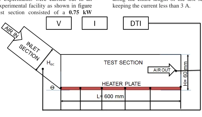
The experiments were carried out in an open-loop experimental facility as shown in figure 3.1. The test section consisted of a 0.75 kW
[image:2.595.122.469.198.400.2]exhaust fan, the heat transfer test section. The rectangular test section of length L= 600 mm, with mm inner height (H) 60 mm Width (W) 100 mm depicted in fig 1. The G.I. Sheet Plate heater is placed at the bottom of the rectangular channel to provide a uniform heat flux boundary condition. The electrical output power was controlled by a variance transformer to obtain a constant heat flux along the entire length of the test section and by keeping the current less than 3 A.
Fig 1 Schematic diagram of experimental heat transfer set-up. The outer surface of the rectangular
channel was well insulated to minimize convective
heat loss to surroundings, and necessary
precautions were taken to prevent leakages from the system. The inner and outer temperatures of the bulk air were measured at certain points with a
[image:2.595.108.531.519.672.2]multichannel temperature measurement unit in conjunction with the k-type thermocouples as can be seen in Figure. 3.1. Six thermocouples were placed on the surface of the heater plate ofto measure the surface temperature variation.
Figure 2 Actual Experiment Set-up
Fig 1 represents the inlet conditions arrangement used in the present work. The inlet conditions duct was made of G.I. Sheet with 600 mm in length and its height and width were 60 mm and 100 mm, respectively. The width of the entry channel (inlet section) will remain unchanged but
76 The inlet channel is also well insulated and proper
care has been taken to provide a leak proof joints.
3.1 Experimental Procedure
In the apparatus setting above, the inlet bulk air at Atmospheric temperature (°C)is sucked from a rectangular channel section by exhaust fan. The anemometer is used to measure the velocity of air (V m/s), which is helpful in calculating the mass flow rate of air (m m3/s). Also, the pressuredrop in the heat transfer test section was measured with water U-tube manometers.
[image:3.595.75.279.372.542.2]The volumetric air flow rates can be the adjusted by varying speed of exhaust fan through the regulator, situated on the switch panel. During the experiments, the bulk air was heated by an adjustable electrical heater wrapping along the test section. Both the inlet and outlet temperatures of the bulk air from the tube were measured by multi-channel k-type (nikel-chromium) thermocouples. It was necessary to measure the temperature at 6 stations altogether on the surface of the heater for finding out the average Nusselt number.
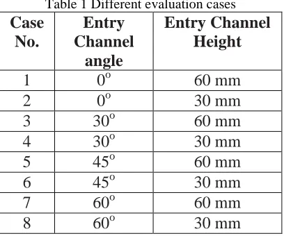
Table 1 Different evaluation cases
Case
No.
Entry
Channel
angle
Entry Channel
Height
1
0
o60 mm
2
0
o30 mm
3
30
o60 mm
4
30
o30 mm
5
45
o60 mm
6
45
o30 mm
7
60
o60 mm
8
60
o30 mm
For each test run, it was necessary to record the data of temperature, velocity of air and
pressure drop of the bulk air at steady state conditions. The various characteristics of the flow, the Nusselt number, and the Reynolds number were based on the average of tube wall temperatures and outlet air temperature. The local wall temperature, inlet and outlet air temperatures, the pressure drop across the test section and air flow velocity were measured for heat transfer for different entry conditions shown in table 3.1. The average Nusselt numbers were calculated and discussed where all fluid properties were determined at the overall bulk mean temperature. The experiments are conducted on test rig and then analyses are done.
4. RESULTS AND DISCUSSION
In this experimentation the heat transfer rate in a rectangular duct is analyzed. First we conducted the experimentation with the normal (Linear) entry Channel in which the height of the entry channel is same as that of the test section, this will be the reference for our experimentation and is showing the minimum rate of heat transfer. The experimental is divided in two phase one is the angle of entry channel is changed such as 30 o, 45 o, and 60o.In second phase the height of entry channel is changed from 60 mm to 30 mm with the different entry angles.
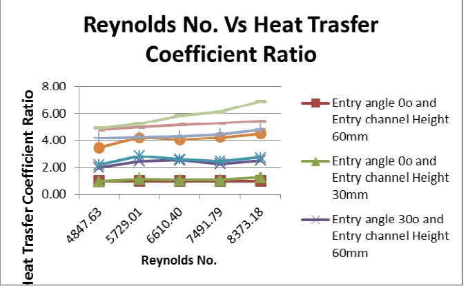
4.1 Reynolds No. Vs Heat Transfer Coefficient
77 Figure 3 Heat Transfer Coefficient Vs Reynolds No.
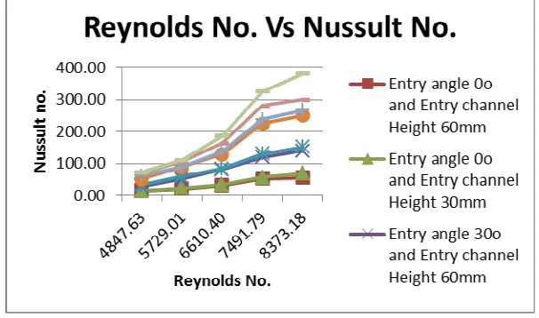
4.2 Nusselt No. Vs Reynolds No.
The above graph is plotted for Reynolds no. against the Nussult No.. As shown in graph the Reynolds no is taken on the X-Axis and Nussult No. on the Y- Axis. The Nussult No. increases with the change in Entry angle of the entry section as shown in graph with a significant rate as compared to the rectangular channel without any modified entry conditions. This increase in the heat transfer is depends on the many factors but Nussult No. plays vital role in it. The graph shows that the Nussult No. for the different entry conditions is
more as compare to the heat transfer rate in the channel in normal entry conditions. The Nussult no. increases with the change in the entry angle which incereses as the angle of entry conditions changes. The nussult no. also affects with the change in entry height of the channel. The graph shows that the nussult no. is increases as the Reynolds no. increases. This increases in the heat transfer rate occurred due to the turbulence occurred with the change in the entry conditions.
[image:4.595.146.449.473.652.2]78
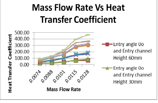
[image:5.595.148.450.117.313.2]4.3 Heat transfer coefficient Vs mass flow rate.
Figure 5 Mass Flow Rate Vs Heat Transfer Coefficient The above graph is plotted for Mass flow
rate against the heat transfer coefficient. As shown in graph the mass flow rate is taken on the X-Axis and heat transfer coefficient on the Y- Axis. The heat transfer rate increases with the change in Entry angle as shown in graph with a significant rate as compared to the ordinary rectangular channel. This increase in the heat transfer is depends on the many factors but heat transfer coefficient plays vital role in it. The graph shows that the heat transfer coefficient for the different entry conditions is more as compare to the heat transfer rate in the channel without any entry modifications. The change in heat transfer rate can also see as the inclination angle of entry channel increases the heat transfer rate is also increases. The graph shows that the heat transfer rate is increases as the Mass flow rate increases. This increases in the heat transfer rate occurred due to the turbulence.
4.4 Nusselt No. Vs mass flow rate
79 Figure 6 Mass Flow Rate Vs Nussult No.
4.5 Heat transfer enhancement Vs Reynolds No.
The below graph is plotted for heat transfer enhancement against Reynolds no. the rate of heat transfer enhancement in rectangular channel with varied inclination angle of entry channel and different channel height is shown in comparison with the heat transfer rate in rectangular channel under normal entry conditions. The graph shows
the heat transfer enhancement in rectangular channel with different cases. The rate of heat transfer enhancement with entry angle 30o, 45o and 60o is 2.5, 4 and 6 respectively. Also the graph shows the around 10 to 15% increases in the heat transfer rate as the duct height is reduced to 50%.
[image:6.595.130.469.457.666.2]80
5. CONCLUSION
Experimental investigations have been
carried out to study the effects of modified inlet conditions in a rectangular channel on heat transfer rate and enhancement efficiency. We modified the inclination angle of entry channel to 30o, 45o , 60o and 90o in rectangular channel also we have reduced the height of entry channel with the change in inclination angle as mentioned above.
The experimentation first were conducted on the rectangular channel without any change in the inlet conditions and then all the modifications were done. These results are compared with the first case and the enhancement rate is calculated. The heat transfer in the rectangular channel could be promoted by modifying the entry angle of duct which creates the turbulence in the rectangular channel and we can increase the rate of heat transfer, while it brings about the energy loss of the fluid flow. The average heat transfer enhancement with entry angle 30 o, 45 o and 60
o is 2.5, 4 and 6 respectively. Also the graph shows the
around 10 to 15% increases in the Nussult No. as the duct height is reduced to 50%
Hence we can conclude that the Use of Inclined entry channel increases the rate of heat transfer also it increases as the angle of inclination increases. Also the change in the channel height is also results in enhancement of heat transfer.
REFERENCES
[1] Carl-Olof Olsson, BengtSunden b “Experimental study of Flow and heat transfer in rib-roughened rectangular channels”, ; Experimental Thermal and Fluid Science 16 (1998) 349 to365.
[2] Isak KOTCIOGLU, Tr. J., “Heat Transfer and Flow Structure in a Rectangular Channel With Wing-Type Vortex Generator”, of Engineering and Environmental Science, 22 (1998) , 185 – 195. [3] M. Emin Erdoğan and C. Erdem Imrak, “The
Effects Of Duct Shape On The Nusselt Number”,
Mathematical and Computational Applications,
Vol. 10, No. 1, pp. 79-88, 2005
[4] K.H. Ko, N.K. Anand, “Use of porous baffles to enhance heat transfer in a rectangular channel”, Heat Mass Transfer 46 (2003) 4191–4199.
[5] J.M. Choi, N.K. Anand, Heat transfer in a serpentine channel with a series of right-angle turns, Numer. Heat Transfer, Part A 23 (1993) 189–210.
[6] J.M. Choi, N.K. Anand, S.C. Lau, R.T. Kukreja, “Heat (Mass) transfer in a serpentine channel with right-angled turns”, ASME J. Heat Transfer 118 (1996) 211–213.
[7] S.W. Chang, T.M. Liou, K.F. Chiang, G.F. Hong, “Heat transfer and pressure drop in rectangular channel with compound roughness of V-shaped ribs and deepened scales”, Heat Mass Transfer 51 (2008) 457–468.
[8] R. Kiml, A. Magda, S. Mochizuki, A. Murata, “Rib-induced secondary flow effects on local circumferential heat transfer distribution inside a circular ribroughened tube”, Int. J. Heat Mass Transfer 47 (2004) 1403–1412.
[9] M.E. Taslim, T. Li, D. Kercher, “Experimental heat transfer and friction in channels roughened with angle, V-shaped, and discrete ribs on two opposite walls”, ASME J. Turbomach. 118 (1996) 20–28.
[10] J.C. Han, Y.M. Zang, C.P. Lee, “Augmented heat transfer in square channels with parallel, crossed, and V-shaped angled ribs”, ASME J. Turbomach. 113 (1991) 590–597.
[11] H.H. Cho, S.J. Wu, H.J. Kwon, “Local heat/mass transfer measurement in a rectangular duct with discrete ribs”, ASME J. Turbomach. 122 (2000) 579–586.
[12] R.L. Webb, E.R.G. Eckert, J. Goldstein, “Heat transfer and friction in tubes with roughness”, Int. J. Heat Mass Transfer 14 (1971) 601–617.
[13] X. Gao, B. Sunde´ n, “Heat transfer and pressure drop measurements in rib roughened rectangular ducts”, Exp. Therm. Fluid Sci. 24 (2001) 25–34. [14] J.C. Han, Y.M. Zang, “Augmented heat transfer in
square channels with parallel [15] tube using a baffle”, Int. J. Heat Fluid
BIOGRAPHIES
Mr. Bharat .R Wandhare1
1 MTech HPE Student, Mechanical
Engineering, Dbacer Nagpur, Maharashtra, India
Dr. S. V. Prayagi2
2
HOD, Mechanical Engineering, Dbacer Nagpur, Maharashtra, India
Prof. G. D. Gosavi3
3 Asst. Professor, Mechanical