Mechanics of Discontinuous Materials
Thesis by
Kimberley Ann Mac Donald
In Partial Fulfillment of the Requirements for the Degree of
Doctorate of Philosophy in Mechanical Engineering
CALIFORNIA INSTITUTE OF TECHNOLOGY Pasadena, California
2020
© 2020
Kimberley Ann Mac Donald ORCID: 0000-0003-4512-9740
ACKNOWLEDGEMENTS
Most people who have undertaken a PhD would likely agree that it is not a task that can be completed alone. A great many people have made this thesis possible both directly and indirectly. To thank each of them is a daunting task, but in the next several paragraphs I will attempt to acknowledge some of them.
First, thank you to my advisor, Ravi Ravichandran for his cheerful greetings of "hey, how’s it going?" and constant encouragement to "just do it!" Thank you also for introducing me to so many varied topics and avenues for exploration. Thank you to José Andrade for seeing a potential for my work far beyond anything I could have seen myself. I would also like to thank Kathy Faber for her astounding influence on me as a person, a mentor, and a researcher. To Melany Hunt, thank you for agreeing to serve on my committee, and for allowing me to be a part of your outreach efforts in Giving Voice. Thank you also to Mike Mello for always being interested in talking about whatever I have on my mind and for many great discussions on my research.
For most of my time at Caltech, I was fortunate to be a part of an interdisciplinary fracture mechanics research group. Thank you to Kaushik Bhattacharya, Ravi Ravichandran, Kathy Faber, and Blaise Bourdin for teaching me so much and for helping me think critically about my work from a variety of perspectives. I also need to thank the students and post docs in this group for their constant support, ideas, and encouragement: Louisa Avellar, Stella Brach, Neal Brodnik, Chun-Jen Hsueh, and Nha Tran.
Thank you to Ryan Hurley for mentoring me through my first Summer at Caltech. I appreciate all the time and energy you put into guiding me. Thank you also to Eloïse Marteau for teaching me how to use GEM, sharing your codes and example data, and helping me trouble shoot when I ran into problems. Thank you to Bob Grubbs for teaching me polymer chemistry and helping me understand and improve my inverse suspension polymerization method. Thank you to Red Lhota for training me on the rheometer, for helping me in polymer chemistry class, and for being an incredibly helpful and kind person.
Wilbert in the Biological Imaging Facility have been similarly invaluable. I also need to thank several past members of Ravi’s research group. In particular, thank you to Jacob Notbohm and Christian Franck for passing on so much of your mi-croscopy and image correlation knowledge. Thank you also to the Ravi and Kaushik research groups: Louisa, Zach, Christian, Owen, Matt, Moriah, Paul, Dingyi, Jin, Vinamra, Tomo, Tori, Ying Shi, Zev, Korhan, Leah, and many others.
Thank you to all the friends (whether at Caltech or elsewhere) who have been with me through this adventure. Your support and encouragement has been incredible: Zoila, Rachel, Ellen, Melissa, Voon, Bekah, Kirsti, Serena, Emily, Camille, Josh, Abbey, Zach, Rachel, Christie, Justin, Nina, Terri, Jim, Lisa, Debi, Joseph, BD, Russel, and Thomas. Thank you in particular to Blaire, Georgina, Hanako, and Alex for being there for me even though we have been physically far apart for the past few years.
Thank you to my first research advisor, Jim Giancaspro at the University of Miami. I would not be where I am today without the support and guidance you gave me. Thank you also to my research mentors and mentees, you have taught me so much in out short time together: Shan Yuan, Lauren Millman, Eunice Yoon, and Polina Verkhovodova.
Thank you also to my mother. Your support of me has been unwavering and I do not think I would have been able to do this without your encouragement. Thank you to my sister for being there through thick and thin. Thank you also to my grandfather for the stories that captured my interest and led me to science and engineering.
ABSTRACT
The complexity and multiscale nature of material microstructures introduces sig-nificant intricacies to many mechanics problems for which we do not have a full theoretical understanding. Under loading, these microstructures can introduce sig-nificant nonlinearities that cannot be described sufficiently by current theories and models. This leads us to consider experiments we could perform to improve our understanding of such effects. This thesis describes the design of experiments exploring two aspects of material microstructure effects: (i) crack propagation and renucleation in soft brittle polymers and (ii) interparticle forces in granular materials.
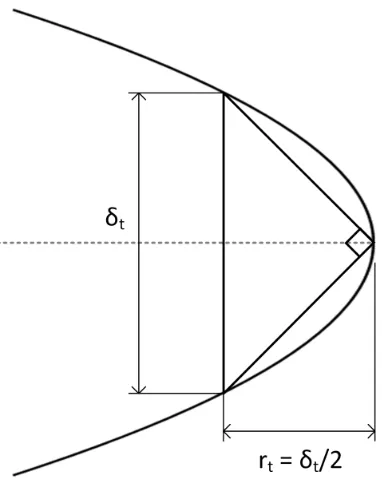
First, experimental and analysis methods are developed to study fracture mechanics in soft brittle polymers with the goal of developing a more detailed understanding of the effects of microstructural heterogeneities on crack propagation and renucleation in three-dimensions. To better understand these processes, experiments on crack propagation in thin soft polymers using confocal microscopy images are conducted. Traditional metrics associated with crack propagation including stress intensity fac-tor (SIF,K) and energy release rate (ERR,G) are calculated by direct measurement of the crack tip opening displacement (CTOD,δt) on the sub-millimeter scale. Er-rors in these calculations are comparable to those reported in the literature for more traditional fracture experiment geometries. Fluorescent speckle images are cap-tured using confocal microscopy imaging, a fast and low cost 3D optical imaging technique, to study crack geometry during propagation. Images of renucleation events are also captured allowing investigation of factors contributing to slow crack roughening observed by earlier researchers. The goal of this study is to provide an experimental method to enhance understanding of crack interactions with mi-crostructural heterogeneities and of renucleation events, which can significantly improve our ability to design material toughness.
PUBLISHED CONTENT AND CONTRIBUTIONS
[1] K. A. Mac Donald and G. Ravichandran. “Confocal microscopy and digital volume correlation methods for intergranular force transmission experiments”.
Experimental Techniques, 2018. doi: 10.1007/s40799- 018-0292-8. K.A.M.D. participated in the conception of the project, conducted the experi-ments, analyzed the data, and wrote the manuscript.
[2] K. A. Mac Donald and G. Ravichandran. “Crack propagation and renucleation in soft brittle hydrogels”. 2019. Submitted.
TABLE OF CONTENTS
Chapter II: Crack Propagation and Renucleation in Soft Brittle Hydrogels . . 29
Bibliography . . . 55
Chapter III: Confocal Microscopy and Digital Volume Correlation Methods for Intergranular Force Transmission Experiments . . . 59
3.1 Introduction . . . 60
3.2 Materials and Methods . . . 61
Specimens . . . 61
Imaging . . . 62
Experimental Design . . . 63
3.3 Analysis, Results, and Discussion . . . 65
2D Analysis . . . 67
3D Analysis . . . 71
3.4 Conclusions . . . 76
Bibliography . . . 79
Chapter IV: Summary and Future Work . . . 85
4.1 Future Work . . . 86
Mechanics of slow crack roughening . . . 86
3D analysis of fracture toughening . . . 87
Granular mechanics in 3D . . . 87
LIST OF ILLUSTRATIONS
Number Page
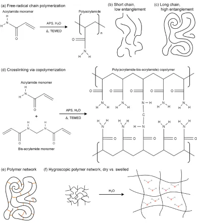
1.1 Linear and network polyacrylamide systems . . . 4 1.2 Ashby plot of stiffness modulus versus fracture energy for several
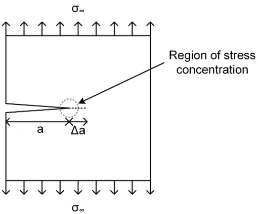
materials . . . 5 1.3 Elastic perfectly plastic material model for 1D tension loading. . . 9 1.4 Infinite plate with an edge crack of length, a subjected to far field
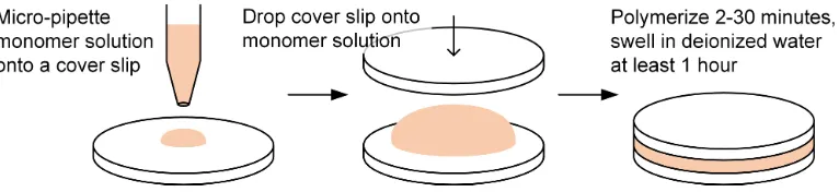
loading,σ∞. . . 9 1.5 Particle level force chains carry a continuum level compressive load . 12 1.6 Illustration of the transmission confocal microscope concept . . . 14 2.1 Procedure for casting thin polyacrylamide hydrogels between cover
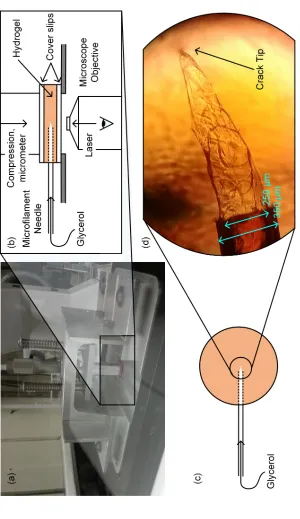
slips. . . 33 2.2 Fracture experiment configuration for stable slow crack growth using
hydrostatic pressure . . . 34 2.3 Parabolic crack opening profile with the crack tip opening displacement 39 2.4 2D DIC displacement and strain results indicating evidence of stress
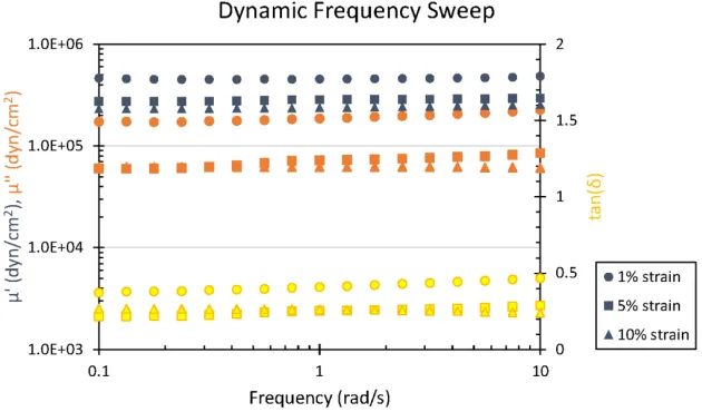
concentration ahead of crack tip . . . 41 2.5 Dynamic frequency sweep analysis of the gel at different strain levels. 42 2.6 Crack opening and propagation shapes . . . 44 2.7 Crack tip opening displacement (CTOD),δtc, versus measured crack
advance,∆a. . . 45 2.8 An example of 2D crack renucleation . . . 48 2.9 Gray scale intensity variation during a renucleation event . . . 49 2.10 3D representation of an initial crack shape (yellow) and location prior
to crack propagation in a volumetric speckle image. . . 51 2.11 Crack tip opening displacement variation through the specimen
thick-ness from the cover slip surface (z = 0 µm) to approximately the middle of the gel (z =120 µm). . . 52 2.12 Crack tip location (a) vs. CTOD (δ) vs. depth (z) . . . 53
3.1 Compression loading device mounted to microscope stage showing the micrometer used to apply displacement loading to the specimen. . 64 3.2 Example of 2D speckle pattern of a slice in a 3D granular assembly
3.3 Images of the granular assembly specimen, Granular 2: (a)
ortho-graphic projections and (b) z-stack sum 2D image. . . 68
3.4 Images of Suspension Polymerization Particles (SPP): (a) ortho-graphic projections and (b) 3D projection-view. . . 69
3.5 2D DIC displacement results for a granular assembly . . . 70
3.6 2D Granular Element Method (GEM) analysis results for interparticle forces . . . 72
3.7 Schematic showing how the volumetric image is partitioned into individual grains . . . 73
3.8 3D displacement and GEM results for a granular assembly . . . 74
3.9 3D DVC and strain results for a single grain . . . 77
LIST OF TABLES
Number Page
NOMENCLATURE
Abbreviations
µCT Micro-computed tomography
AFM Atomic force microscopy
CTOD Crack tip opening displacement,δt
DEM Discrete element method
DIC Digital image correlation
DVC Digital volume correlation
GEM Granular element method
PMT Photomultiplier tube
ROI Region of interest
SEM Scanning electron microscopy
SIF Stress intensity factor,K
XRD X-ray diffraction
Symbols
δ Crack opening profile
δΩ Derivative of the volume, the surface, used for integration
δt Crack tip opening displacement
1D strain
γ Surface energy
µ Bulk modulus
∇· Divergence, dot product of the gradient operator with a vector field
∇ Gradient operator
ν Poisson’s ratio
Stain tensor σ Stress tensor
a Acceleration vector
b Body force vector
n Normal vector
u Displacement vector
A Area
a Crack length
d Spatial dimension
E Young’s modulus
G Energy release rate
Gc Critical energy release rate
J Rice’s J-integral, see J. R. Rice,J. Appl. Mech,35(2):379–386, 1968.
K Stress intensity factor
Kc Critical stress intensity factor
r Radius, in polar coordinates the distance from the origin
rt The distance from the crack tip to the point where crack tip opening displace-ment is measured
rN L Estimate of the size of the nonlinear region
S Surface area
U Potential energy
V Volume
Terminology
Confocal Common focus, often refers to confocal microscopy which uses pinholes and objective lenses to capture light from a single point in volumetric space
Fractography The study of fracture surfaces using images to identify key charac-teristics of the fracture event
Pixel 2D image unit representing a measure of illumination for a single point in a 2D plane
C h a p t e r 1
INTRODUCTION
The goal of the work described in this dissertation is first and foremost to advance understanding of the mechanics of materials beyond continuum models and toward improving deformation and damage models and predictions. This is achieved by employing three-dimensional (3D) quantitative visualization techniques such as digital image and digital volume correlation (DIC, DVC) to characterize the full-field displacements. By moving away from thinking of materials as a continuum and toward thinking of them as a discontinuous material system, we can broaden the scope of both material models and damage models while learning more about the complexity of mechanical processes that impact the behavior of the material system.
1.1 Motivation
If we think about a traditional engineering material such as metal, we can think about the grain structure and how the crystal structure of each grain affects the stiffness and toughness of a component manufactured from that metal. Typically, we, as engineers, are happy to know that models and design parameters predict that our component will not fail under some load limit. But we also desire to know what will happen if that load limit is exceeded. When and where will the component fail? The scientist in us now begins to ask how will it fail?
having grain-like structures, or even having components with grain structures similar to what is seen in metals, the grains do not have the same interface properties as the grains in metals. Wood has a complex directional cellular structure where cells have layered walls and each wall is composed of a network of cellulose fibrils in a cellulose and lignin matrix [11]. Concrete has a cementitious matrix around sand and gravel particles that each have their own underlying granular structure [12]. Similarly FRP and FRC have a polymer or ceramic matrix respectively around fibrous inclusions that may be randomly dispersed or ordered in a woven mat [13]. Taking a polymer alone, there is a great deal of complexity in the chain entanglements or cross-linked network structure that significantly alters how we think about damage processes [14].
The complexity of the materials described above goes beyond the material system. Much of the research conducted on these materials measures global or continuum level behavior. In order to understand local behavior, full-field methods such as image correlation are employed but are often limited to the outer surface of the material [15]. Probing the full complexity of the three-dimensional nature of these material systems is typically a challenging and costly endeavor involving diffraction and tomography methods [10, 16–23].
This thesis presents experimental methods and work on fracture and granular me-chanics problems using model materials or systems. Material properties, param-eters, and mechanics quantities are measured from optical images and used to demonstrate the capabilities of these experimental methods as well as to improve our understanding of material deformation and damage processes.
1.2 Discontinuous Materials
Rather than thinking about the global behavior of a material or component, we want to understand how the microstructure of the material affects its local behavior and properties. Throughout this thesis polymers are used as model materials to study brittle fracture and granular mechanics. The structure and fracture behavior of the polymer itself is also of interest beyond its use as a model brittle material.
Polymers
can be used to form a network polymer where the chains are not only entangled, but are also chemically bonded to each other, typically resulting in a stiffer more elastic solid material [24–29]. Some of these crosslinked network polymers are hydrophilic and absorb water into the pores formed between the chains. Fig. 1.1(d) demonstrates the polymerization of poly(acrylamide-bis-acrylamide) copolymer, the network hydrogel used in this thesis and (f) shows a diagram of how the network swells when it absorbs water [30–34].
As polymers deform under loading their chains move and reorient. In the case of an entangled chain polymer, the individual chains can move relative to each other. Longer chains are typically more entangled which limits this motion [14]. If the polymer is networked, the chains have fixed bonds to other chains or to themselves, directly limiting relative motion of the chains at these crosslink sites [33].
Damaged and fractured materials
Many polymers, including polyacrylamide, have very brittle fracture behavior. This means they possess low fracture toughness and energy, and fractography shows smooth fracture surfaces without indicators of plasticity such as voids or large permanent deformations. Traditional fracture theories predict that these polymers will exhibit fracture behavior and properties similar to other very brittle materials like ceramics and glasses [34, 35].
Unlike these very stiff brittle materials, hydrogels are very compliant with stiffnesses several orders of magnitude lower than those of ceramics, glasses, and even structural polymers such as PMMA. This means that the deformations at failure in gels are expected to be several orders of magnitude larger, and thus more easily measurable, than in the stiffer materials [35]. When a crack propagates in a sheet of glass, the crack opening before propagation is on the order of nanometers [36]. Scanning electron microscopy (SEM) is one of the few methods by which such small features can be measured. Conducting fracture tests on glasses in-situin an SEM presents many challenges that limit further study of brittle fracture [37]. However, in a typical soft gel, the crack opening at propagation is in the tens to hundreds of micrometers or larger [7, 38]. At this scale, the crack is measurable via numerous optical techniques. This allows for a wide array of experimental configurations to advance understanding of brittle fracture processes using a polymer gel as a model brittle material.
Figure 1.2: Ashby plot of stiffness modulus versus fracture energy for several ma-terials. Adapted from Naficy et al. (2011) with permission from CSIRO Publishing [34]. Typical property ranges for conventional hydrogels are highlighted in orange and typical properties for human biological tissues are shown in pink.
rameter. In some formulations, when this parameter is equal to one the material is undamaged and when it is equal to zero the material is completely damaged and can no longer bear load. This is classified as failure or fracture [39, 40]. However, such a model does not describe or account for the processes that lead to the damage and fracture.
cracks through sharp changes in deformation gradients [42–45].
Over the last several years, advances in additive manufacturing technology have opened the way for designing, engineering, and printing microstructured materials. Several systems exist that allow for printing in multiple materials with different mechanical properties. For example, the Statasys Connex3 allows for a single print to use up to three different polymer materials with different mechanical properties. This printer can also mix the base polymers allowing for a range of material properties in a single print. Several researchers have begun exploring how this technology can be used to design material systems with enhanced fracture properties.
Several experiments on enhancing the adhesive properties of tape by using variation in the tape stiffness have demonstrated in a one-dimensional sense that elastic contrast interfaces between regions of different stiffnesses produce a toughening effect [46–48]. This work has been extended to the two-dimensional case using the Stratasys Connex3 and similar technologies to produce material systems with a wide array of toughening geometries. The simplest of these is a striped geometry with alternating stiff and compliant stripes normal to the crack [49, 50]. Circular and moon shaped inclusion arrays have also been studied as well as brick and mortar type arrays inspired by the structure of nacre [51]. All of these geometries are, however, two-dimensional and do not fully take advantage of the opportunities additive manufacturing technology allows.
Nevertheless, these studies show the powerful toughening effect engineered material discontinuities can have on the fracture properties of materials. Further study of these effects is needed to be able to effectively design such microstructures.
Granular media
Particle inclusions is one of the many ways we can toughen a material. From nanoparticles in rubber to sand and gravel aggregates in concrete, particle inclusions affect stress distributions and increase the energy necessary for a crack to propagate through a material [55–60]. While granular materials are of interest as toughening mechanisms, their mechanical properties and behavior without a matrix are also of great interest.
From building foundations and overpass embankments to food grains and pharma-ceuticals, the unique mechanical behavior of granular materials impacts our lives on a daily basis. When we think about foundations and embankments, we want these structures to behave like solids. But when we think about commercial processing of grains and pharmaceuticals, we want to take advantage of granular flow. De-pending on grain size and shape as well as boundary conditions like slope angles and retaining walls, a given load may be supported but the grains or they may flow [61–66].
To understand these phenomena and when a granular structure will transition from behaving like a solid to flowing like a fluid, we need to think about the structure in terms of its individual grains rather than approximating it as a continuous material [67–70]. Similarly, when we think about particles as toughening inclusions, there is a lot to learn about the mechanisms of toughening by understanding how the inclusion and matrix deform and fracture as separate entities. In this way, we can view granular materials as discontinuous. We can also view a material that has been toughened via particle inclusions as discontinuous.
1.3 Mechanics
According to the Collins English Dictionary, mechanics describes "the branch of science, divided into statics, dynamics, and kinematics, concerned with the equilib-rium or motion of bodies in a particular frame of reference." In the field of mechanics of materials, we typically use the classical mechanics formulations based on New-ton’s Laws of Motion. First the concept of equilibrium which can be described for a deformable body in general form by Eq. 1.1
∇ ·σ+ ρb= ρa, (1.1)
Balance of angular momentum can be used to show symmetry of the stress tensor for the continuum as written in Eq. 1.2
σ =σ|, (1.2)
where(·)| indicates the transpose.
These two equations are, however, not enough to describe the deformations that result form the action of the forces on a body. To relate the forces to deformations, or stresses to strains, a constitutive material model is required. Currently, material models are not derived from fundamental physics but rather are determined by fitting experimental data to a pre-defined model. Depending on the material, scale, boundary conditions, and loading, different models can be used [71].
In the simplest case, we make several assumptions: First we assume the material is a homogeneous continuum, then we further assume isotropy, meaning the material behavior is independent of loading direction. We then assume the material has a linear elastic response to loading, or in 1D, σ = E, where E is the Young’s modulus or stiffness of the material and is the strain [71]. For small deformations in traditional materials with simple geometries and loading conditions, this linear elastic isotropic constitutive model works well. However, it does not account for stresses that exceed the material’s elastic limit. When the yield stress is exceeded, plastic deformations begin, and when the ultimate stress is exceeded it can no longer carry any load [60]. Ductile materials typically experience significant permanent deformations before failure while brittle materials typically fail with little evidence of yielding.
There are several methods to account for plastic yielding and failure in material models. Perhaps one of the simplest is to assume an elastic perfectly plastic model. That is, to assume that once the yield stress is reached, the material no longer supports additional load and the stress cannot increase, as illustrated in Fig. 1.3. Although this model allows the material to yield, it does not describe final failure of the material. For this, we need to turn to fracture mechanics.
Fracture mechanics
Figure 1.3: Elastic perfectly plastic material model for 1D tension loading.
Figure 1.4: Infinite plate with an edge crack of length, a subjected to far field loading,σ∞.
The effect of stresses on a deformable body can be understood as the energy needed to deform that body by a fixed amount. Thus, excess energy can be thought of as the energy which is expended by forming or propagating a crack through the material. Griffith described this as the potential energy and related it to the energy needed to break atomic bonds [72, 73]. He defined a critical energy release rate as
Gc =2γ, (1.3)
whereγ is the energy needed to create a new surface and a crack is considered to consist of two newly created surfaces [76].
general fracture using this idea of energy release rate or the energy necessary to propagate the crack in Fig. 1.4 by the infinitesimal distance∆aas
G= −δU
δa, (1.4)
whereUis the potential energy andais the initial crack length [72, 73].
Brittle materials have much lower critical fracture energies than more ductile ma-terials. Often, fracture toughness is measured and described by the critical stress intensity factor (SIF),Kc, rather than the critical fracture energy,Gc, for traditional engineering materials. SinceKcis related to Gc and the material’s stiffness by Eq. 1.5 we can think of the fracture energy as the square of the toughness normalized by the stiffness [72, 73].
Eis the Young’s modulus, andν is Poisson’s ratio.
In general, although we know that stiffer materials may have very high toughness like metals or very low toughness like ceramics, we often assume that more com-pliant materials will have a lower toughness. However, due to their chemistry and microstructures, biological, polymeric, and composite materials may not follow this trend. For example, hydrogels that have been toughened by double networking exhibit fracture energies comparable to much stiffer plastics while retaining most of the extreme compliance of a gel. On the other hand, conventional hydrogels are extremely compliant and exhibit fracture energies comparable to glasses and ceramics [34, 35].
In this thesis, fracture energy is used to describe the resistance of a conventional polymer hydrogel to fracture due to the nature of its networked microstructure.
Granular mechanics
constrained; they can now rotate and slide against each other. This leads to the unique ability of granular materials to behave like both solids and liquids [61, 66, 67, 77].
In many civil engineering applications engineers design granular materials to behave as solids and liquid-like flow is considered as a failure mode. Here, the majority of theories and design equations treat the granular material as a continuum. In industrial processes like commercial grain and pharmaceutical processing, engineers want these materials to behave as fluids and flow through equipment like hoppers. Here also, the granular material is often treated as a continuum in models and design equations. However, all these models and equations are specific to a certain geometry and loading condition. There is no universal continuum model that can describe a granular materials solid-like and fluid-like behaviors and the transition between them [77, 78].
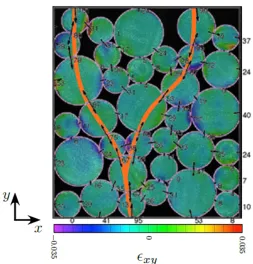
Over the last few decades significant work has been done to improve our under-standing of granular mechanics by considering grains as discrete particles. Several experimental techniques have been used to demonstrate how continuum level loads are carried via interparticle force chains in granular assemblies. Force chains are described as sets of particles in an assembly that carry large compressive loads while other particles near by experience much lower loads [68, 69, 79, 80]. Graphically, this concept is demonstrated in Fig. 1.5. The load applied to the upper boundary is carried primarily by two force chain branches that meet and transfer the load to the lower boundary. When the load exceeds a critical limit, force chains break and reconfigure. When the chains break, the particles are free to move relative to each other and can therefore flow. When flow happens in a narrow band through a granular specimen is is known as shear band failure, which is a very common mechanism of failure in granular structures [63, 69].
Figure 1.5: Particle level force chains carry a continuum level compressive load through a granular specimen. Adapted from Hurley et al. (2014) with permission from Elsevier [68].
1.4 Quantitative Visualization
To advance both granular mechanics and fracture mechanics theories, we need to expand experimental capabilities to be able to understand grain-level and micro-structural-level effects in a fully three-dimensional sense. Computational power for modeling, imaging, and analysis has greatly increased in recent years making these experiments and analyses more achievable than ever before [64, 83, 84].
Installing hundreds of thousands of minuscule strain gages or load cells on each particle in a granular specimen or distributed throughout a fracture specimen is not only impractical, it also affects the behavior of the specimens themselves. For this reason, volumetric imaging methods combined with quantitative analyses are becoming increasingly popular [85–88]. These methods are also being employed to improve modeling capabilities for complex geometries [12, 22, 89].
Volumetric imaging methods
Diffraction methods such as neutron diffraction and X-ray diffraction (XRD) use interactions between the beam and the nucleus and electron clouds of atoms re-spectively to "image" specimens. In both of theses methods, average strain in crystallographic materials can be measured by determining the change in atomic spacing as a result of loading [4, 5, 12, 63, 67, 90, 91].
Tomographic scanning of a specimen can be used to build a 3D image of the geometry and grain structure. When X-rays are used with tomographic scanning it is commonly called micro-computed tomography (µCT.) This method is often used in the medical industry to image a patient’s internal organs but it is also used in the aerospace and automotive industries for non-destructive assessment and inspection of parts and assemblies for damage and defects. More recently, it has been used for understanding mechanics and fracture inside opaque materials [62, 64, 70, 83, 84].
While these methods can provide excellent resolution both spatially and for mea-suring strains, they are very expensive and often highly time consuming. The diffraction methods also necessitate a material with a crystal structure in order to be able to measure grain strains via changes in atomic spacing. Tomographic image reconstruction is very challenging and can result in errors due to imaging artifacts [90, 92, 93].
Confocal Microscopy
Confocal microscopy is an optical volumetric imaging method that is much less expensive and less time consuming than the methods described above. As with any experimental method, it also has its own unique limitations among its many benefits.
The word "confocal" means having a common focus. This concept is illustrated in Fig. 1.6 for a transmission confocal microscope set up. The black lines show light that goes through the upper pinhole, is focused at the focal plane, and then transmitted through the lower pinhole to be captured by the detector. The dashed red lines show light that is not in the focal plane and is therefore not transmitted through the pinhole and captured by the detector. Most confocal microscopy systems capture reflected or emitted light rather than transmitted so incorporate a beam splitter to redirect the reflected or emitted light to the detector [94–97]. Commonly, this light is in the visible spectrum but it is also possible to use ultraviolet and infrared wavelengths just outside of the visible spectrum.
stage up or down in the vertical-direction.
Figure 1.6: Illustration of the transmission confocal microscope concept where the black lines of light are in the focal "point" and the dashed red lines are out of focus and therefore not captured.
Some confocal systems use photo-multiplier tubes (PMTs) to capture the light intensity of individual voxels. When multiple PMTs are used, dif-ferent light wavelength ranges can be captured separately allowing for iden-tification and separation of different features in a specimen. Swept field and spinning disc systems usually use a CCD or CMOS camera and are typ-ically faster because they capture sev-eral voxels or a line of voxels at once. While this does introduce some noise from spurious light reflections from adjacent pixels, it can exponentially increase scanning speeds. Addition-ally, CCD or CMOS camera cannot inherently filter different wavelengths of light so filters may need to be used in some applications [94, 95].
In most cases, lasers and fluorescent dyes or particles are used in confocal microscopy imaging. The laser ex-cites the fluorescent molecules using a wavelength close to the peak exci-tation and the molecule then emits a photon at a lower wavelength known as the peak emission wavelength. The intensity of this emission is captured by the PMT or camera [94, 95].
the organelles [98].
Some researchers are using confocal microscopy to study how cells move, com-municate, and respond to stimuli in 3D by measuring the deformations of a gel substrate around the cell. This is achieved by casting fluorescent microspheres into the gel and using these as tracking particles or as speckles for image correlation type methods [97, 99–104]. This suggests that a similar method could be used to study the mechanics of the polymer material itself in 3D [85]. It also motivates considering the wealth of geometries and loading conditions that could be studied [105–107].
One of the primary limitations of confocal microscopy is that in order to capture volumetric images, the material must have good optical transparency. Spatial res-olution and optical constraints also limit the size of specimens and the imaging window. While this method is significantly faster than diffraction and tomogra-phy methods, raster scanning is still relatively slow compared to many material mechanical processes such as crack propagation.
Image correlation methods
In studying the mechanics of materials, several quantities need to be calculated or measured. A common way to measure full-field deformations is by using image correlation methods such as digital image correlation (DIC). A random pattern, often speckles, acts as a unique identifier for subsets of the image. Each subset in a reference image is matched to a subset in the deformed image by finding the closest pattern match using a cross-correlation coefficient. Displacements are then calculated for each subset and strains can be calculated from these deformations [108]. Then, knowing material properties allows for calculation of stresses. When boundary conditions and loading are well defined, material properties can be inferred from the deformation and strain results.
3D-DIC typically refers to the use of a multi-camera system to determine out-of-plane deformations. Digital volume correlation (DVC) extends the idea of DIC to volumetric space to determine the full 3D displacements and strains in a material. Most algorithms match subsets by allowing them to have both free-body motion and to deform but only measure the displacements directly [108, 109]. Strains are typically determined by computing the deformation gradient from the displacements.
relative motions of the material on either side of a crack or between particles which artificially impact both displacement and strain measures. For fracture experiments, regions of interest (ROI) are commonly defined to exclude the final crack geometry [42–45]. For granular specimens, it is generally necessary to define an ROI for each particle individually [68, 110].
In addition to correlation methods, images can be used to measure geometric quan-tities such as particle shapes and areas in the case of granular materials. These parameters also allow for determining particle contacts and when combined with average strains determined using a correlation method become the inputs for the granular element method (GEM), an inverse solution method to determine interpar-ticle forces [63, 68, 81, 110].
Granular element method
The granular element method (GEM) uses the discrete element method (DEM) as a basis and incorporates a contact law for interparticle friction. The formulation includes balance of forces and moments,Keqf =0, the average stress in each particle, Kstf = bst where bstp = Ωpσp, and friction constraint equations, Bf ≥ 0. The inverse problem is solved as a minimization subject to constraints as in Eq. 1.7 as follows:
f =arg min f,Bf≥0
(λ||Keqf||+(1−λ)||Kstf−bst||), (1.7)
where the preferred solution is determined by the knee point of the curve (||Keqf||,
||Kstf−bst||.) The full formulation of GEM can be found in the following references: [64, 68, 81, 82, 110, 111].
Applying GEM to experiments allows for determination of interparticle forces which can be used to understand force chains and how a granular material carries load. Images are used to extract geometric descriptors known as the granular fabric and correlation methods with a constitutive model for the particle’s material are used to determine average particle stresses.
1.5 Outline
Chapter 2 describes work on understanding fracture processes in hydrogels. Slow stable crack propagation is achieved using fluid pressure in thin soft polymer gel specimens. Confocal microscopy is used to capture 2D internal plane fluorescent speckle images during propagation events and 3D volumetric images are captured before propagation and after crack arrest. Analysis of fracture energy shows that higher energy is needed to renucleate a crack after it arrests. Based on assessment of these renucleation events and on through thickness variation in crack shape, toughening mechanisms are suggested as contributors to the slow crack surface roughening observed by other researchers. Further experiments to better understand these effects are suggested. This experimental method is also recommended to improve understanding of interface and inclusion toughening effects.
Chapter 3 describes several aspects of conducting intergranular force transmission experiments using confocal microscopy imaging techniques. Commercially avail-able fluorescently marked polymer spheres are considered as a potential model granular material. While the speckle pattern is excellent for image correlation tech-niques and the particle size is good for the scale of confocal microscopy imaging, the particles’ optical properties are not appropriate for this imaging method. A method to produce custom in-house manufactured spheres with a volumetric speckle pattern that could be easily imaged using a confocal microscope is also presented. Imaging and DVC capabilities for a large gel sphere are then presented and suggest that many new granular experiments can be conducted using these particles with the described experimental technique.
REFERENCES
[1] W. T. Read. Dislocations in crystals. McGraw-Hill, 1953.
[2] J. P. Hirth, J. Lothe, and T. Mura. Theory of dislocations (2nd ed.). Journal of Applied Mechanics, 50(2):476–477, June 1983. ISSN 0021-8936. doi: 10.1115/1.3167075.
[3] A. N. Stroh. The cleavage of metal single crystals. The Philosophical Mag-azine: A Journal of Theoretical Experimental and Applied Physics, 3(30): 597–606, 1958. doi: 10.1080/14786435808565802.
[4] J. Oddershede, S. Schmidt, H. F. Poulsen, L. Margulies, J. Wright, M. Mosci-cki, W. Reimers, and G. Winther. Grain-resolved elastic strains in de-formed copper measured by three-dimensional X-ray diffraction. Ma-terials Characterization, 62(7):651–660, 2011. ISSN 1044-5803. doi: 10.1016/j.matchar.2011.04.020.
[5] U. Lienert, T. S. Han, J. Almer, P. R. Dawson, T. Leffers, L. Margulies, S. F. Nielsen, H. F. Poulsen, and S. Schmidt. Investigating the effect of grain interaction during plastic deformation of copper. Acta Materialia, 52(15): 4461–4467, 2004. ISSN 1359-6454. doi: 10.1016/j.actamat.2004.05.051.
[6] J. Marrow, C. Reinhard, Y. Vertyagina, L. Saucedo-Mora, D. Collins, and M. Mostafavi. 3D studies of damage by combined X-ray tomography and digital volume correlation. Procedia Materials Science, 3:1554–1559, 2014. ISSN 2211-8128. doi: 10.1016/j.mspro.2014.06.251.
[7] F. Baldi, F. Bignotti, I. Peroni, S. Agnelli, and T. Riccò. On the measurement of the fracture resistance of polyacrylamide hydrogels by wire cutting tests.
Polymer Testing, 31(3):455–465, 2012. ISSN 0142-9418. doi: 10.1016/j. polymertesting.2012.01.009.
[8] J. P. Gong and Y. Osada. Soft and wet materials: From hydrogels to biotissues. In M. Cloitre, editor,High Solid Dispersions, pages 203–246. Springer Berlin Heidelberg, Berlin, Heidelberg, 2010. ISBN 978-3-642-16382-1. doi: 10. 1007/12_2010_91.
[9] R. Long and C.-Y. Hui. Fracture toughness of hydrogels: measurement and interpretation.Soft Matter, 12(39):8069–8086, 2016. ISSN 1744-683X. doi: 10.1039/C6SM01694D.
[11] R. B. Miller. Chapter 2 - Structure of wood. InWood handbook—Wood as an engineering material. General Technical Report FPL–GTR–113. U.S. De-partment of Agriculture, Forest Service, Forest Products Laboratory, Madi-son, WI, 1999. ISBN 978-0-88415-474-7. doi: https://doi.org/10.2737/FPL-GTR-113.
[12] O. K. Mahabadi, B. S. A. Tatone, and G. Grasselli. Influence of microscale heterogeneity and microstructure on the tensile behavior of crystalline rocks.
Journal of Geophysical Research: Solid Earth, 119(7):5324–5341, 2014. ISSN 2169-9356. doi: 10.1002/2014JB011064.
[13] R. M. Jones. Mechanics of composite materials, 2nd Ed. Taylor & Francis, Philadelphia, Penn, 1999. ISBN 156032712X.
[14] G. Odian. Principles of Polymerization. Wiley InterScience electronic col-lection. Wiley, 2004. ISBN 978-0-471-47874-4.
[15] T. A. Berfield, J. K. Patel, R. G. Shimmin, P. V. Braun, J. Lambros, and N. R. Sottos. Micro- and nanoscale deformation measurement of surface and internal planes via digital image correlation. Experimental Mechanics, 47 (1):51–62, 2007. ISSN 0014-4851. doi: 10.1007/s11340-006-0531-2.
[16] J. Lachambre, J. Réthoré, A. Weck, and J.-Y. Buffiere. Extraction of stress intensity factors for 3d small fatigue cracks using digital volume correlation and X-ray tomography. International Journal of Fatigue, 71:3–10, 2014. ISSN 0142-1123. doi: 10.1016/j.ijfatigue.2014.03.022.
[17] J. Lachambre, A. Weck, J. Réthoré, J.-Y. Buffière, and J. Adrien. 3D analysis of a fatigue crack in cast iron using digital volume correlation of X-ray tomographic images. In H. Jin, C. Sciammarella, C. Furlong, and S. Yoshida, editors,Imaging Methods for Novel Materials and Challenging Applications, Volume 3: Proceedings of the 2012 Annual Conference on Experimental and Applied Mechanics, pages 203–209. Springer New York, New York, NY, 2013. ISBN 978-1-4614-4235-6. doi: 10.1007/978-1-4614-4235-6_28.
[18] N. Limodin, J. Réthoré, J.-Y. Buffière, A. Gravouil, F. Hild, and S. Roux. Crack closure and stress intensity factor measurements in nodular graphite cast iron using three-dimensional correlation of laboratory X-ray microtomography images. Acta Materialia, 57(14):4090–4101, 2009. ISSN 1359-6454. doi: 10.1016/j.actamat.2009.05.005.
[20] M. Mostafavi, N. Baimpas, E. Tarleton, R. C. Atwood, S. A. McDonald, A. M. Korsunsky, and T. J. Marrow. Three-dimensional crack observation, quantification and simulation in a quasi-brittle material. Acta Materialia, 61 (16):6276–6289, 2013. ISSN 1359-6454. doi: 10.1016/j.actamat.2013.07. 011.
[21] M. Mostafavi, S. A. McDonald, P. M. Mummery, and T. J. Marrow. Ob-servation and quantification of three-dimensional crack propagation in poly-granular graphite. Engineering Fracture Mechanics, 110:410–420, 2012. ISSN 0013-7944. doi: 10.1016/j.engfracmech.2012.11.023.
[22] J. Rannou, N. Limodin, J. Réthoré, A. Gravouil, W. Ludwig, M.-C. Baïetto-Dubourg, J.-Y. Buffière, A. Combescure, F. Hild, and S. Roux. Three dimen-sional experimental and numerical multiscale analysis of a fatigue crack.
Computer Methods in Applied Mechanics and Engineering, 199(21–22): 1307–1325, 2009. ISSN 0045-7825. doi: 10.1016/j.cma.2009.09.013.
[23] Y. Tanaka, K. Fukao, Y. Miyamoto, and K. Sekimoto. Discontinuous crack fronts of three-dimensional fractures.EPL (Europhysics Letters), 43(6):664, 1998. ISSN 0295-5075.
[24] E. M. Ahmed. Hydrogel: Preparation, characterization, and applications: A review. Journal of Advanced Research, 6(2):105–121, 2013. ISSN 2090-1232. doi: 10.1016/j.jare.2013.07.006.
[25] N. Annabi, J. W. Nichol, X. Zhong, C. Ji, S. Koshy, A. Khademhosseini, and F. Dehghani. Controlling the porosity and microarchitecture of hydrogels for tissue engineering. Tissue Engineering. Part B, Reviews, 16(4):371–383, 2010. ISSN 1937-3368 1937-3376. doi: 10.1089/ten.teb.2009.0639.
[26] A. K. Denisin and B. L. Pruitt. Tuning the range of polyacrylamide gel stiffness for mechanobiology applications.ACS Applied Materials & Interfaces, 8(34): 21893–21902, 2016. ISSN 1944-8244. doi: 10.1021/acsami.5b09344.
[27] C. A. Grattoni, H. H. Al-Sharji, C. Yang, A. H. Muggeridge, and R. W. Zimmerman. Rheology and permeability of crosslinked polyacrylamide gel.
Journal of Colloid and Interface Science, 240(2):601–607, 2001. ISSN 0021-9797. doi: 10.1006/jcis.2001.7633.
[28] S. Kiatkamjornwong and P. Phunchareon. Influence of reaction parameters on water absorption of neutralized poly(acrylic acid-co-acrylamide) synthe-sized by inverse suspension polymerization.Journal of Applied Polymer Sci-ence, 72(10):1349–1366, 1999. ISSN 1097-4628. doi: 10.1002/(SICI)1097-4628(19990606)72:10<1349::AID-APP16>3.0.CO;2-K.
[30] T. Bertrand, J. Peixinho, S. Mukhopadhyay, and C. W. MacMinn. Dynamics of swelling and drying in a spherical gel. Physical Review Applied, 6(6), 2016. doi: 10.1103/PhysRevApplied.6.064010.
[31] T. R. C. Boyde. Swelling and contraction of polyacrylamide gel slabs in aqueous solutions. Journal of Chromatography A, 124(2):219–230, 1976. ISSN 0021-9673. doi: 10.1016/S0021-9673(00)89737-X.
[32] R. Brighenti, A. Spagnoli, A. Carpinteri, and F. Artoni. Notch effect in highly deformable material sheets. Thin-Walled Structures, 105(Supplement C):90–100, 2016. ISSN 0263-8231. doi: 10.1016/j.tws.2016.03.030.
[33] A. Grillet. Polymer gel rheology and adhesion. In N. Wyatt, L. Gloe, and J. De Vicente, editors, Rheology, page Ch. 3. InTech, Rijeka, 2012. doi: 10.5772/36975.
[34] S. Naficy, H. R. Brown, J. M. Razal, G. M. Spinks, and P. G. Whitten. Progress toward robust polymer hydrogels.Australian Journal of Chemistry, 64(8):1007–1025, 2011.
[35] S. Agnelli, F. Baldi, F. Bignotti, A. Salvadori, and I. Peroni. Fracture char-acterization of hyperelastic polyacrylamide hydrogels.Engineering Fracture Mechanics, 2018. ISSN 0013-7944. doi: 10.1016/j.engfracmech.2018.06. 004.
[36] M. V. Swain, J. C. Metras, and C. G. Guillemet. XIIth international congress on glass: A deformation and fracture mechanics approach to the scoring and breaking of glass. Journal of Non-Crystalline Solids, 38:445–450, 1980. ISSN 0022-3093. doi: 10.1016/0022-3093(80)90459-7.
[37] E. Bouchbinder and T. Goldman and J. Fineberg. The dynamics of rapid fracture: instabilities, nonlinearities and length scales. Reports on Progress in Physics, 77(4):046501, 2014. ISSN 0034-4885.
[38] T. Baumberger, C. Caroli, D. Martina, and O. Ronsin. Magic angles and cross-hatching instability in hydrogel fracture. Physical Review Letters, 100 (17):178303, 2008. doi: 10.1103/PhysRevLett.100.178303.
[39] I. Einav, G. T. Houlsby, and G. D. Nguyen. Coupled damage and plasticity models derived from energy and dissipation potentials.International Journal of Solids and Structures, 44(7–8):2487–2508, 2006. ISSN 0020-7683. doi: 10.1016/j.ijsolstr.2006.07.019.
[41] T. Brenner, S. Matsukawa, K. Nishinari, and R. Johannsson. Failure in a soft gel: Delayed failure and the dynamic yield stress.Journal of Non-Newtonian Fluid Mechanics, 196:1–7, 2012. ISSN 0377-0257. doi: 10.1016/j.jnnfm. 2012.12.011.
[42] J. Réthoré, F. Hild, and S. Roux. Extended digital image correlation with crack shape optimization. International Journal for Numerical Methods in Engineering, 73(2):248–272, 2008. ISSN 1097-0207. doi: 10.1002/nme. 2070.
[43] J. Réthoré, S. Roux, and F. Hild. An extended and integrated digital image correlation technique applied to the analysis of fractured samples. European Journal of Computational Mechanics, 18(3-4):285–306, 2009. ISSN 1779-7179. doi: 10.3166/ejcm.18.285-306.
[44] J. Réthoré, S. Roux, and F. Hild. Optimal and noise-robust extraction of fracture mechanics parameters from kinematic measurements. Engineering Fracture Mechanics, 78(9):1827–1845, 2011. ISSN 0013-7944. doi: 10. 1016/j.engfracmech.2011.01.012.
[45] S. Roux, J. Réthoré, and F. Hild. Digital image correlation and fracture: an advanced technique for estimating stress intensity factors of 2d and 3d cracks. Journal of Physics D: Applied Physics, 42(21):214004, 2009. ISSN 0022-3727.
[46] L. Avellar, T. Reese, K. Bhattacharya, and G. Ravichandran. Effect of cohesive zone size on peeling of heterogeneous adhesive tape. Journal of Applied Mechanics, 85(12):121005–121005–7, 2018. ISSN 0021-8936. doi: 10. 1115/1.4041224.
[47] S. Xia, L. Ponson, G. Ravichandran, and K. Bhattacharya. Toughening and asymmetry in peeling of heterogeneous adhesives. Physical Review Letters, 108(19):196101, 2012.
[48] S. M. Xia, L. Ponson, G. Ravichandran, and K. Bhattacharya. Adhesion of heterogeneous thin films—I: Elastic heterogeneity.Journal of the Mechanics and Physics of Solids, 61(3):838–851, 2013. ISSN 0022-5096. doi: 10.1016/ j.jmps.2012.10.014.
[49] C.-J. Hsueh, L. Avellar, B. Bourdin, G. Ravichandran, and K. Bhattacharya. Stress fluctuation, crack renucleation and toughening in layered materials.
Journal of the Mechanics and Physics of Solids, 120:68 – 78, 2018. ISSN 0022-5096. doi: https://doi.org/10.1016/j.jmps.2018.04.011.
[51] L. T. Avellar. Observations of Failure Phenomena in Periodic Media. Dis-sertation (Ph.D.), California Institute of Technology, 2018.
[52] M. L. Cooke and D. D. Pollard. Fracture propagation paths under mixed mode loading within rectangular blocks of polymethyl methacrylate.Journal of Geophysical Research: Solid Earth, 101(B2):3387–3400, 1996. ISSN 2156-2202. doi: 10.1029/95JB02507.
[53] S. Y. Wang, S. W. Sloan, D. C. Sheng, and C. A. Tang. 3d numerical analysis of crack propagation of heterogeneous notched rock under uniaxial tension. Tectonophysics, 677–678:45–67, 2016. ISSN 0040-1951. doi: 10.1016/j.tecto.2016.03.042.
[54] J. Zuo, X. Deng, M. A. Sutton, and C.-S. Cheng. Three-dimensional crack growth in ductile materials: Effect of stress constraint on crack tunneling.
Journal of Pressure Vessel Technology, 130(3):031401–031401–8, 2008. ISSN 0094-9930. doi: 10.1115/1.2937738.
[55] A. F. Bower and M. Ortiz. Solution of three-dimensional crack problems by a finite perturbation method.Journal of the Mechanics and Physics of Solids, 38 (4):443–480, 1990. ISSN 0022-5096. doi: 10.1016/0022-5096(90)90008-R.
[56] E. N. Brown, N. R. Sottos, and S. R. White. Fracture testing of a self-healing polymer composite. Experimental Mechanics, 42(4):372–379, 2002. ISSN 1741-2765. doi: 10.1007/bf02412141.
[57] H. Gao and J. R. Rice. A first-order perturbation analysis of crack trapping by arrays of obstacles. Journal of Applied Mechanics, 56(4):828–836, 1989. ISSN 0021-8936. doi: 10.1115/1.3176178.
[58] H. Gao. A boundary perturbation analysis for elastic inclusions and interfaces.
International Journal of Solids and Structures, 28(6):703–725, 1991. ISSN 0020-7683. doi: 10.1016/0020-7683(91)90151-5.
[59] J. W. Hutchinson. Mechanisms of toughening in ceramics. In Theoretical and Applied Mechanics, pages 139–144. Elsevier, Amsterdam, 1989. ISBN 978-0-444-87302-6. doi: 10.1016/B978-0-444-87302-6.50017-X.
[60] J. J. Reinosa, A. del Campo, and J. F. Fernández. Indirect measurement of stress distribution in quartz particles embedded in a glass matrix by using confocal Raman microscopy.Ceramics International, 41(10, Part A):13598– 13606, 2015. ISSN 0272-8842. doi: 10.1016/j.ceramint.2015.07.155.
[62] S. A. Hall, M. Bornert, J. Desrues, Y. Pannier, N. Lenoir, G. Viggiani, and P. Besuelle. Discrete and continuum analysis of localised deformation in sand using X-ray µCT and volumetric digital image correlation. Géotechnique, 60:315–322, 2010.
[63] S. A. Hall, J. Desrues, G. Viggiani, P. Bésuelle, and E. Andò. Experimental characterisation of (localised) deformation phenomena in granular geomate-rials from sample down to inter-and intra-grain scales. Procedia IUTAM, 4: 54–65, 2012. ISSN 2210-9838. doi: 10.1016/j.piutam.2012.05.007.
[64] R. C. Hurley, S. A. Hall, J. E. Andrade, and J. Wright. Quantifying inter-particle forces and heterogeneity in 3D granular materials. Physical Review Letters, 117(9):098005, 2016.
[65] D. Muir Wood and D. Leśniewska. Stresses in granular materials. Granular Matter, 13(4):395–415, 2011. ISSN 1434-5021. doi: 10.1007/s10035-010-0237-0.
[66] F. Radjai, D. E. Wolf, M. Jean, and J.-J. Moreau. Bimodal character of stress transmission in granular packings. Physical Review Letters, 80(1):61–64, 1998.
[67] S. A. Hall, J. Wright, T. Pirling, E. Andò, D. J. Hughes, and G. Viggiani. Can intergranular force transmission be identified in sand? Granular Matter, 13 (3):251–254, 2011. ISSN 1434-5021. doi: 10.1007/s10035-011-0251-x.
[68] R. Hurley, E. Marteau, G. Ravichandran, and J. E. Andrade. Extracting inter-particle forces in opaque granular materials: Beyond photoelasticity.
Journal of the Mechanics and Physics of Solids, 63(0):154–166, 2014. ISSN 0022-5096. doi: 10.1016/j.jmps.2013.09.013.
[69] A. Tordesillas and M. Muthuswamy. On the modeling of confined buckling of force chains.Journal of the Mechanics and Physics of Solids, 57(4):706–727, 2009. ISSN 0022-5096. doi: 10.1016/j.jmps.2009.01.005.
[70] I. Vlahinić, E. Andò, G. Viggiani, and J. E. Andrade. Towards a more accurate characterization of granular media: extracting quantitative descriptors from tomographic images. Granular Matter, 16(1):9–21, 2014. ISSN 1434-7636. doi: 10.1007/s10035-013-0460-6.
[71] A. F. Bower. Applied Mechanics of Solids. CRC Press, 2009. ISBN 978-1-4398-0248-9.
[72] T. L. Anderson.Fracture Mechanics: Fundamentals and Applications, Third Edition. CRC Press, 2005. ISBN 978-1-4200-5821-5.
[74] J. W. Hutchinson. A course on nonlinear fracture mechanics. Dept. of Solid Mechanics, Technical University of Denmark, 1979.
[75] J. W. Hutchinson. Micro-mechanics of damage in deformation and fracture. Dept. of Solid Mechanics, Technical University of Denmark, 1987.
[76] A. A. Griffith and T. G. Ingram. VI. The phenomena of rupture and flow in solids. Philosophical Transactions of the Royal Society of London. Series A, Containing Papers of a Mathematical or Physical Character, 221(582-593): 163–198, 1921. doi: 10.1098/rsta.1921.0006.
[77] P. Jop, Y. Forterre, and O. Pouliquen. A constitutive law for dense granular flows. Nature, 441(7094):727–730, 2006. ISSN 0028-0836. doi: 10.1038/ nature04801.
[78] H. P. Zhu, Z. Y. Zhou, R. Y. Yang, and A. B. Yu. Discrete particle simulation of particulate systems: A review of major applications and findings.Chemical Engineering Science, 63(23):5728–5770, 2008. ISSN 0009-2509. doi: 10. 1016/j.ces.2008.08.006.
[79] N. Brodu, J. A. Dijksman, and R. P. Behringer. Spanning the scales of granular materials through microscopic force imaging. Nat Commun, 6, 2015. doi: 10.1038/ncomms7361.
[80] R. C. Hurley. Force chains, friction, and flow: Behavior of granular media across length scales. Dissertation (Ph.D.), California Institute of Technology, 2016.
[81] J. E. Andrade, K.-W. Lim, C. F. Avila, and I. Vlahinić. Granular element method for computational particle mechanics.Computer Methods in Applied Mechanics and Engineering, 241–244:262–274, 2012. ISSN 0045-7825. doi: 10.1016/j.cma.2012.06.012. URL http://www.sciencedirect.
com/science/article/pii/S0045782512002009.
[82] K.-W. Lim and J. E. Andrade. Granular element method for three-dimensional discrete element calculations. International Journal for Numerical and An-alytical Methods in Geomechanics, 38(2):167–188, 2014. ISSN 1096-9853. doi: 10.1002/nag.2203.
[83] S. Cottrino, Y. Jorand, E. Maire, and J. Adrien. Characterization by X-ray tomography of granulated alumina powder during in situ die compaction.
Materials Characterization, 81:111–123, 2013. ISSN 1044-5803. doi: 10. 1016/j.matchar.2013.04.004.
[85] J. Y. Huang, X. C. Pan, S. S. Li, X. L. Peng, C. Y. Xiong, and J. Fang. A digital volume correlation technique for 3-D deformation measurements of soft gels. International Journal of Applied Mechanics, 3(2):335–354, 2011. ISSN 1758-8251. doi: 10.1142/s1758825111001019.
[86] A. I. Hussein, P. E. Barbone, and E. F. Morgan. Digital volume correlation for study of the mechanics of whole bones. Procedia IUTAM, 4:116–125, 2012. ISSN 2210-9838. doi: 10.1016/j.piutam.2012.05.013.
[87] M. Sjödahl, C. R. Siviour, and F. Forsberg. Digital volume correlation applied to compaction of granular materials. Procedia IUTAM, 4:179–195, 2012. ISSN 2210-9838. doi: 10.1016/j.piutam.2012.05.020.
[88] J. Réthoré, N. Limodin, J.-Y. Buffière, F. Hild, W. Ludwig, and S. Roux. Digital volume correlation analyses of synchrotron tomographic images.The Journal of Strain Analysis for Engineering Design, 46(7):683–695, 2011. ISSN 0309-3247. doi: 10.1177/0309324711409999.
[89] M. S. Wu. Strategies and challenges for the mechanical modeling of biological and bio-inspired materials. Materials Science and Engineering: C, 31(6): 1209–1220, 2010. ISSN 0928-4931. doi: 10.1016/j.msec.2010.11.012.
[90] L. Margulies, T. Lorentzen, H. F. Poulsen, and T. Leffers. Strain tensor development in a single grain in the bulk of a polycrystal under loading.Acta Materialia, 50(7):1771–1779, 2002. ISSN 1359-6454. doi: 10.1016/S1359-6454(02)00028-9.
[91] R. V. Martins, L. Margulies, S. Schmidt, H. F. Poulsen, and T. Leffers. Simul-taneous measurement of the strain tensor of 10 individual grains embedded in an Al tensile sample. Materials Science and Engineering: A, 387–389: 84–88, 2004. ISSN 0921-5093. doi: 10.1016/j.msea.2004.02.069.
[92] H. Leclerc, S. Roux, and F. Hild. Projection savings in CT-based digital volume correlation. Experimental Mechanics, 55(1):275–287, 2014. ISSN 1741-2765. doi: 10.1007/s11340-014-9871-5.
[93] T. Taillandier-Thomas, S. Roux, T. F. Morgeneyer, and F. Hild. Localized strain field measurement on laminography data with mechanical regulariza-tion.Nuclear Instruments and Methods in Physics Research Section B: Beam Interactions with Materials and Atoms, 324:70–79, 2013. ISSN 0168-583X. doi: 10.1016/j.nimb.2013.09.033.
[94] D. M. Sheppard and C. R. J. Shotton. Confocal Laser Scanning Microscopy. Number 38 in Royal Microscopy Society Microscopy Handbooks. Springer-Verlag, New York, USA, 1997. ISBN 0-387-91514-1.
[96] C. Franck. Quantitative characterization of 3D deformations of cell inter-actions with soft biomaterials. Dissertation (Ph.D.), California Institute of Technology, 2008.
[97] J. K. Notbohm. Dynamics of cell–matrix mechanical interactions in three dimensions. Dissertation (Ph.D.), California Institute of Technology, 2013.
[98] M. A. Hemphill, B. E. Dabiri, S. Gabriele, L. Kerscher, C. Franck, J. A. Goss, P. W. Alford, and K. K. Parker. A possible role for integrin signaling in diffuse axonal injury. PLoS ONE, 6(7):e22899, 2011. doi: 10.1371/journal. pone.0022899.
[99] C. Franck, S. A. Maskarinec, D. A. Tirrell, and G. Ravichandran. Three-dimensional traction force microscopy: A new tool for quantifying cell-matrix interactions. PLoS ONE, 6(3):e17833, 2011. doi: 10.1371/journal. pone.0017833.
[100] J. Y. Huang, X. L. Peng, L. Qin, T. Zhu, C. Y. Xiong, Y. Y. Zhang, and J. Fang. Determination of cellular tractions on elastic substrate based on an integral boussinesq solution. Journal of Biomechanical Engineering-Transactions of the Asme, 131(6):9, 2009. ISSN 0148-0731. doi: 10.1115/1.3118767.
[101] S. A. Maskarinec, C. Franck, D. A. Tirrell, and G. Ravichandran. Quanti-fying cellular traction forces in three dimensions. Proceedings of the Na-tional Academy of Sciences, 106(52):22108–22113, 2009. doi: 10.1073/ pnas.0904565106.
[102] J. Notbohm, J. H. Kim, A. R. Asthagiri, and G. Ravichandran. Three-dimensional analysis of the effect of epidermal growth factor on cell-cell adhesion in epithelial cell clusters. Biophysical Journal, 102(6):1323–1330, 2012. ISSN 0006-3495. doi: 10.1016/j.bpj.2012.02.016.
[103] J. Notbohm, A. Lesman, D. A. Tirrell, and G. Ravichandran. Quantifying cell-induced matrix deformation in three dimensions based on imaging matrix fibers. Integr. Biol., 7(10):1186–1195, 2015. doi: 10.1039/C5IB00013K.
[104] A. Lesman, J. Notbohm, D. A. Tirrell, and G. Ravichandran. Contractile forces regulate cell division in three-dimensional environments.The Journal of Cell Biology, 205(2):155–162, 2014. doi: 10.1083/jcb.201309029.
[105] J. T. Fredrich. 3d imaging of porous media using laser scanning confocal microscopy with application to microscale transport processes. Physics and Chemistry of the Earth, Part A: Solid Earth and Geodesy, 24(7):551–561, 1999. ISSN 1464-1895. doi: 10.1016/S1464-1895(99)00079-4.
[107] E. Merson, V. Danilov, D. Merson, and A. Vinogradov. Confocal laser scan-ning microscopy: The technique for quantitative fractographic analysis. Mod-ern Imaging Techniques in Fracture and Damage Analyses, 183(Supplement C):147–158, 2017. ISSN 0013-7944. doi: 10.1016/j.engfracmech.2017.04. 026.
[108] J. Sutton, H. Schreier, and M. A. Orteu.Image Correlation for Shape, Motion and Deformation Measurements: Basic Concepts, Theory and Applications. Springer US, 1 edition, 2009. ISBN 978-0-387-78747-3. doi: 10.1007/978-0-387-78747-3.
[109] E. Bar-Kochba, J. Toyjanova, E. Andrews, K. S. Kim, and C. Franck. A fast iterative digital volume correlation algorithm for large deformations.
Experimental Mechanics, 55(1):261–274, 2015. ISSN 0014-4851. doi: 10. 1007/s11340-014-9874-2.
[110] E. Marteau and J. Andrade. A novel experimental device for investigating the multiscale behavior of granular materials under shear. Granular Matter, 19, 2017. doi: 10.1007/s10035-017-0766-x.
[111] R. C. Hurley, K. W. Lim, G. Ravichandran, and J. E. Andrade. Dynamic inter-particle force inference in granular materials: Method and application.
C h a p t e r 2
CRACK PROPAGATION AND RENUCLEATION IN SOFT
BRITTLE HYDROGELS
This Chapter is adapted from:
K. A. Mac Donald and G. Ravichandran. “Crack propagation and renucleation in soft brittle hydrogels”. 2019. Submitted.
Abstract
Crack tip opening displacement (CTOD) and fracture energy are determined from crack geometry and material properties for very slowly propagating cracks, less than 50µm/s, in thin brittle hydrogels on the sub-millimeter scale. 2D fluorescent speckle images are captured using confocal microscopy during propagation, and 3D volumetric images are captured both before propagation begins and after the crack arrests. Fracture energy builds up until a critical value is reached and then remains constant as the crack propagates and eventually arrests when the energy is no longer sufficient for propagation. Once a crack arrests, more energy is needed for renucle-ation, suggesting that local toughening effects are at play. Based on observations of renucleation events and analysis of 3D crack shapes, this local toughening points to a mechanism for fracture surface roughening observed in the literature for slowly propagating cracks. Additionally, through-thickness variation in fracture energy, while expected from linear elastic fracture mechanics (LEFM) theory, suggests lo-cal toughening in the process zone which contributes to this roughening of crack surfaces.
Keywords: brittle, confocal microscopy, fracture mechanics, slow cracks, soft
2.1 Introduction
interest in using such materials in load bearing applications [2, 3]. In soft robotics, gels and other soft materials are used to encase hard components so they feel more life-like. They are also used to build soft actuators to perform delicate tasks like picking up glasses or eggs and in realistic joints to minimize friction [4, 5]. In the field of biomedical devices one of the major challenges is producing functional, comfortable, and bio-compatible implants and devices. Many biological tissues are very compliant, so implants and devices with high stiffnesses are likely to cause significant inflammation, leading to scarring and rejection of the implant [6]. Ad-vancements in additive manufacturing techniques have led to interest in printing customized scaffolds for cell growth. Nutrient transport through the scaffold is critical to be able to grow cells in complex geometries [7]. Additionally, it has been shown that substrate stiffness has a great effect on cell growth [8–10]. This suggests that in order to move toward printing viable simple organs, scaffolds must be compliant enough to allow proper growth of cells and tissues.
One of the major drawbacks of conventional synthetic soft materials is their low toughness. Since hydrogels are compliant, they can undergo large deformations but they also typically exhibit very brittle fracture. There are several methods that can be used to increase gel toughness such as double networking which can produce gels with mechanical and fracture responses comparable to biological tissues [5, 11, 12]. Hydrogels also show excellent potential for improving cardiac implants because they can be manufactured with stiffnesses as low as that of cardiac muscle, one of the most compliant yet toughest tissues in the human body.
In addition to their uses in biological applications, conventional hydrogels offer a unique opportunity to improve our understanding of fracture mechanics for both soft and brittle materials. The fracture toughness of conventional hydrogels is comparable to that of ceramics and glasses, but they undergo significantly larger and therefore measurable displacements within the linear elastic regime, making them good candidates for investigating fracture of brittle materials [13–16]. Further study of fracture in conventional gels will also provide insights into the mechanics of toughened gels.
the crack front. At faster rates these ridges do not form but micro-scale generalized roughening is still observed. Another fracture behavior unique to soft hydrogels is fracturing as a result of contact stresses at the gel-water-air interface. Studies have been conducted examining the natural periodicity in formation of such cracks depending on gel thickness. It has been suggested that these cracks then propagate due to the hydrostatic pressure resulting from capillarity [19].
In this chapter we present an experimental method that allows us to measure fracture energy in a soft brittle hydrogel during slow crack propagation on the sub-millimeter scale. Fracture energy is measured using geometric analysis of the crack opening within the linear elastic fracture mechanics (LEFM) regime. Results show the expected characteristic increase in fracture energy followed by a plateau when the crack begins to propagate. Additionally, we visualize renucleation on the scale of the stress concentration near the crack tip and begin to probe the volumetric aspects of fracture by characterizing the crack shape and front. First, we describe the specimens and experimental considerations in Section 2.2. Then, we discuss in Section 2.3 the analysis methods used to measure stress concentration, crack propagation and renucleation, and crack shape. This is followed by a discussion of the results and findings of these 2D and 3D analyses in Section 2.4.
2.2 Materials and Methods
Specimens
A cross-linked polyacrylamide/bis-acrylamide copolymer (polyacrylamide) hydro-gel is chosen as the material for this study because it is a well characterized polymer system that shows excellent optical transparency and has highly tunable mechanical properties. It also exhibits linear elastic response up to 10% strain. Once poly-merized, polyacrylamide is highly inert and is used in many biological applications ranging from soft contact lenses to burn dressings. Gel stiffness and water content can be controlled by adjusting the cross-linker ratio and monomer concentration respectively. Fluorescent microspheres have been used successfully for confocal microscopy imaging and as speckles for image correlation in similar gels for several biomechanics studies [20–22].