ABSTRACT
HU, JIANCHEN. Transaction-level Modeling for a Network-on-chip Router in Multiprocessor Systems. (Under the direction of Prof. William Rhett Davis.)
As the complexity of SoC design grows, the traditional register transfer level (RTL)
centric design flow cannot meet the time to market. In that case, a higher modeling level of
abstraction is need for designer to explore the design space at system level. Transaction-level
model (TLM) is such an approach since it could run much faster than RTL model and also
have enough accuracy. There are different modeling styles of TLM for different applications.
In this thesis, we develop a hybrid-TLM of Network-on-chip (NoC) based on OSCI
TLM-2.0 standard. We use a simplified version of the AMBA AXI protocol for the bus. This
model contains a cycle-accurate AXI router and other periphery modules with
approximately-timed coding style, which achieve fast simulation speed and accurate result.
This model keeps good interoperability since it entirely based on TLM-2.0 standard. And the
Transaction-level Modeling for a Network-on-chip Router in Multiprocessor System
by Jianchen Hu
A thesis submitted to the Graduate Faculty of North Carolina State University
in partial fulfillment of the requirements for the degree of
Master of Science
Computer Engineering
Raleigh, North Carolina
2009
APPROVED BY:
_______________________________ ______________________________ Prof. Xun Liu Prof. Gregory T. Byrd
________________________________ Prof. William Rhett Davis
BIOGRAPHY
Jianchen Hu was born on 4th Sep. 1984 in Beijing, China. He received his Bachelor’s
degree in Electrical Engineering in Tsinghua University in2007. In Fall 2007, he began his
graduate studies in the Electrical and Computer Engineering Department in North Carolina
State University, Raleigh, NC. From June 2008, he has been working in the Methodologies
for User-friendly System-on-a-chip Experimentation (MUSE) group of Prof. Rhett Davis in
the field of network-on-chips in multiprocessor system issue. He will continue his Ph.D
TABLE OF CONTENTS
LIST OF TABLES ...iv
LIST OF FIGURES ...v
CHAPTER 1 INTRODUCTION ...1
1.1 Background...1
1.2 Organization of Thesis...3
CHAPTER 2 TRANSACTION-LEVEL MODELING ...4
2.1 Introduction to transaction-level modeling...4
2.2 OSCI TLM-2.0 standard...10
CHAPTER 3 CROSSBAR BASED ROUTER ARCHITECTURE...12
3.1 AMBA AXI protocol ...12
3.2 Router Structure...18
CHAPTER 4 SYSTEM IMPELMENTATION...27
4.1 Simple bus system in TLM-2.0 ...27
4.2 AXI bus model based on TLM-2.0 ...31
4.3 Simulation result for TLM and RTL model ...39
4.4 Performance analysis...43
CHAPTER 5 CONCLUSTION AND FUTURE WORK ...46
5.1 Conclusion...46
5.2 Future work ...47
REFERRENCES...48
APPENDIX...50
LIST OF TABLES
Table 2.1 SystemC language architecture ...9
Table 3.1 attributes in TLM-2.0 generic payload...14
Table 3.2 Signal description for write address channel...15
Table 3.3 Signal description for write data channel ...16
Table 3.4 Signal description for write response channel...17
LIST OF FIGURES
Fig 2.1 Comparison between RTL and TLM ...4
Fig 2.2 TLM abstraction levels ...7
Fig 2.3 Applications for different coding styles ...8
Fig 2.4 TLM-2.0 architecture...10
Fig 3.1 channel handshake mechanism ...13
Fig 3.2 Four-stage-pipelined router structure...18
Fig 3.3 FIFO in the input queue stage...19
Fig 3.4 Schematic of the decoder at the register-transfer level ...21
Fig 3.5 Schematic of the arbiter ...22
Fig 3.6 Schematic of the crossbar stage ...23
Fig 3.7 FSM for crossbar block in the NoC router...24
Fig 3.8 Timing diagram for the router with 1 master and 1 slave ...25
Fig 3.9 Timing diagram for the router with traffic contention ...26
Fig 4.1 Different type of bus system ...27
Fig 4.2 Block diagram for a 4-phase AT bus...28
Fig 4.3 Router structure in TLM-2.0 SimpleBusAT.h...29
Fig 4.4 Block diagram for target with memory...30
Fig 4.5 Hybrid TLM...32
Fig 4.6 Block diagram of the router in TLM...33
Fig 4.7 Phase transition sequence in a 4-phase protocol...36
Fig 4.8 Phase transition sequence in AXI bus model ...38
Fig 4.9 Simulation result for TLM in case of single-beat transfers...40
Fig 4.10 Simulation result for RTL model in case of single-beat transfers...40
Fig 4.11 Simulation result for TLM in case of multi-beat transfers...42
Fig 4.12 Simulation result for RTL model in case of multi-beat transfers ...43
CHAPTER 1
INTRODUCTION
1.1
Background
One Problem to the SoC (System-on-a-chip) designers today is the gap between the
complexity of ICs and design ability grows larger. The trade-off between product capability
and time to market becomes a big problem for the designer. The designer needs try to
develop complex system in a short period of time, which makes it hard to explore the design
space and find optimum solutions.
As an important subsystem of SoC, Network-on-a-chip (NoC) is widely used in today’s
SoCs, especially in Multiprocessor (MP) systems. Basically, there are two types of on-chip
interconnections: bus-based and NoC. Bus-based interconnection is easy to implement and
has little overhead on area and power. But this type of interconnection usually has low
throughput due to the shared-bus feature. NoC provides much better throughput while
handling traffic congestions, but has large power and area overhead [7]. As the number of
processors grows, the interconnection is required to have high throughput and the ability to
reduce traffic congestion. And the development of three dimensional integrated circuits
(3DICs) allows the designer to build the interconnection across different tiers, which helps
However, there are many factors affecting the NoC performance such as network
topology, flow control, routing, arbitrating algorithm and so on. Hence it is very difficult to
determine the optimum circuit structure and parameters based on the Register Transfer Level
(RTL)-centric design flow. To solve this problem, a new level of abstraction at which people
could explore the design space much faster than RTL begins to interest the designer.
Transaction-level Modeling (TLM) is one such approach [1]. Many works of bus-based
TLM have been stressed and show approximately 100 times simulation speed faster than the
RTL model [9] – [11]. Some works focus on the accuracy of TLM [12], and show the
trade-off between speed and accuracy [13]. But it is still little work on NoC modeling.
In this paper, we build a transaction-level model for an on-chip network router based on
TLM-2.0 standard. The router is fully pipelined, cycle-accurate, and compliant with AMBA
AXI protocol. The router is used for a simple NoC based on TLM-2.0 simple bus. To keep
good interoperability, we modify the basic protocol in TLM-2.0 to add some AXI features in
the router. Then we could connect any types of initiator/target to the router as long as they
use the basic protocol in TLM-2.0.
Many instances of the router could easily be connected with each other to form a
multi-hop network. We envision designer using this model to estimate the throughput of an
1.2
Organization of Thesis
Chapter 2 will introduce the concept of TLM and different transaction-level modeling
styles as well as their advantages/disadvantages. Chapter 3 will discuss the structure and
flow control of the router. Then we put the router in a system which contain several initiators
and targets, and discuss how to build the system under TLM-2.0. In chapter 4 we compare
the simulation results of TLM and RTL model to verify the functional correctness of our
model and to show the cycle-accurate feature of the TLM router. Chapter 5 summarizes the
CHAPTER 2
TRANSACTION-LEVEL MODELING
2.1
Introduction to transaction-level modeling
2.1.1
Concept of TLM
Compared to RTL models, transaction-level models are a higher level of abstraction.
Transaction-level modeling is an approach to modeling digital systems where details of
communication among modules are separated from the details of the implementation of the
functional units or of the communication architecture [1]. As such, TLMs usually do not
include pin-accurate detail like RTL models, but aggregate many input/output signals into
channels. Communications among channels are implemented by calling functions [2].
REG Combinatio nal logic wires
REG MODULE MODULE
Port Channel
(a) Register transfer level model (b) Transaction level model
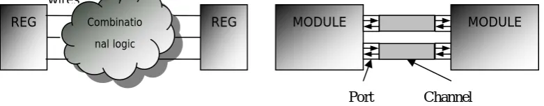
Fig 2.1 Comparison between RTL and TLM
Fig 2.1 illustrates the difference between RTL models and TLMs. In the RTL model,
logics are divided into 2 parts: combinational logic and register slices. And signals are
transferred through wires. In the TLM, high-level packets can be transferred via ports and
(since they are 10 times shorter than RTL models) and run much faster than RTL models
(100 times faster) [9]. Thus, transaction-level models can be used in both design and
verification at system level.
2.1.2
Different modeling style of TLM
Transaction-level models vary in their level of abstraction, depending on module
partitioning and timing. The lowest level of abstraction is an RTL model which strictly
defines the hardware features. RTL models have full cycle-accuracy as well as gate delay in
post-synthesis simulation. The highest level of abstraction is an algorithmic model, which is
an un-timed functional model.
As a level of abstraction between the algorithmic level and register transfer level, the
transaction-level space can be further divided into five levels [3]:
Communication Processes (CP). In this level, the behavior of a system is partitioned
into parallel modules that communicate with each other with complex high-level data
Communication Processes with time (CP+T). Compared to CP, this level adds timing
information. Usually the annotated timing information is multi-cycle estimates. Although
synchronization for different modules needs to be considered in this level, the exact
communication protocol has not been decided.
Programmer’s View (PV). The PV level is much more architecture specified than the
level above. Most SoC designers will develop the system level model in this level. The PV
level is register accurate to the point that low-level software drivers will see an actual
programmer’s representation of the hardware structure.
Programmer’s View with time (PV+T). As the CP+T level, PV+T level adds timing
information to the PV level with greater accuracy. The communication between modules is
resolved to a certain type of interconnection. Hence the timing model could estimate the
transaction delay over the interconnect structure. PV+T level is widely used for hardware
design and verification.
Cycle Accurate (CA). This level captures the micro-architecture details and typically
Fig 2.2 TLM abstraction levels [3]
The levels of abstraction shown in Fig 2.2 are divided into 2 categories: un-timed and
timed. We can further divide the timed models into 3 categories according to the timing
model style: loosely-timed, approximately-timed, and cycle-accurate.
Loosely-timed: this modeling style allows few timing point compared to
approximately-timed and cycle-accurate model. The latency of a transaction is predefined at
the beginning of the transaction. And the functions in modules can be executed ahead of
simulation time, which means the module behavior does not depend on simulation time
strictly.
Approximately-timed: This coding style provides more timing points in a transaction. It
breaks a transaction into several phases. The module could annotate delay in each phase,
which was implemented by using timeout or timed event notification. Approximately-timed
Cycle-accurate: This type of model captures the behavior in each clock cycle. There is
no need to predict the delay before sending a transaction since a cycle-accurate,
clock-triggered module could calculate the delay itself. This is useful when simulating a
complex NoC system. However, this kind of model needs more work on modeling and runs
slower than the loosely-timed and approximately-timed models.
Fig 2.3 Applications for different coding styles [4]
Fig 2.3 shows the applications of TLMs with different coding styles. It is clear that for
hardware applications, approximately-timed (AT) style is preferred. Cycle-accurate style is
not listed since there is no standard for that kind of coding style. In this thesis, we will build
2.1.3
Developing a TLM with SystemC
One important problem is how to describe a TLM. TLM has both hardware and
software features, which leads to the requirement for specifying and validating designs at
multiple levels of abstraction and fast design/simulation speed.
SystemC [14] was created largely in response to the need for TLM. Based on C++,
SystemC provides a serial of classes and methods to help to build TLMs, in addition to RTL
models.
Table 2.1 SystemC language architecture [1]
Standard Channels for Various Models of Computation
Kahn Process Networks, Static dataflow, etc.
Methodology-specified Channels Master/Slave channels, etc.
Elementary Channels
Signal, Timer, Mutex, Semaphore, FIFO, etc. Core Language
Modules, Ports, Processes, Events, Interfaces, Channels
Event-Driven Simulation Kernel
Data-Types
4-valued logic types (01xz)
4-valued logic-vectors, Bits and bit-vectors Arbitrary-precision integers, Fixed-point number, C++ user-defined types
C++ Language Standard
Table 2.1 shows the architecture of SystemC language. The basic layer of SystemC
provides an event-driven simulation kernel. This kernel works with events and processes in
an abstract manner, coordinating events and switching between processes, thereby allowing
SystemC to simulate the implicitly parallel hardware features. Modules and processes
abstraction for communications. Data is transferred between modules through interfaces and
channels. Since SystemC is implemented on top of C++, we can make use of all the C++
features to speed up modeling and increase code reusability.
2.2
OSCI TLM-2.0 standard
OSCI (Open SystemC Initiative) have released a new TLM standard in Jun 2008. It
provides a standardized approach for creating models and transaction-level simulations.
Fig 2.4 shows the architecture of TLM-2.0. One contribution of TLM-2.0 is the
standard transaction type (generic payload) and related interfaces and socket. To maintain
interoperability, TLM-2.0 defines a unified communication mechanism that uses core
interfaces, sockets and a basic protocol.
Different modules send transactions to each other through interfaces and sockets.
Modules are bound with each other via sockets. Compared to the traditional sc_port, sockets
aggregate several interfaces and bind to another sockets with port-export binding method.
Thus, each module with appropriate type of socket could bind with each other, and sends
transactions by calling the relative method of the socket. TLM-2.0 also provides convenient
sockets allowing user to implement their own interface methods and to register them. We
can connect modules by binding these sockets, but define different interface method between
each pair of modules. So the use of socket provides a unified connection structure for
SystemC modules.
TLM-2.0 also defines the generic payload and basic transaction phase to maintain a
basic communication protocol. The basic protocol is accurate enough for simple transactions.
Users can extend the payload with extra attributes and define new phases to implement a
CHAPTER 3
CROSSBAR BASED ROUTER
ARCHITECTURE
3.1
AMBA AXI protocol
Before we design the control flow for the router, we need a transaction protocol.
Advanced Microprocessor Bus Architecture (AMBA) [6] is a widely used on-chip bus
system standard defined and developed by ARM.
The AMBA bus system has several bus protocols, including AHB, APB, multi-layer
AHB, and AXI. In this thesis, we use AXI protocol as our bus protocol, because it is used in
the highest-performance devices. Our goal is to design a NoC router which can handle
multi-beat transfers and can to simulate a multi-hop network by connecting the routers
together.
3.1.1
Channel handshake
AXI protocol specifies five independent channels for each master-slave pair to support
parallel transactions. They are write address channel (AW), read address channel (AR), write
data channel (W), read data channel (R) and write response channel (B). Each channel is one
direction. The AW, AR and W channels are in the forward paths, which means the
channel are in the backward paths. All the AXI channels use the same valid/ready handshake
to transfer data and control information.
The information source uses the VALID signal to show when valid data or control
information is available on the channel. The destination uses the READY signal to show
when it can accept the data. The transfer occurs when both the valid and ready signals are set
to high.
Fig 3.1 channel handshake mechanism [6]
The default value of the ready signal could be either 0 or 1, but the recommended value
is 1 since the transfer could occur once the incoming transaction is available.
3.1.2
Signal description
AXI protocol is a configurable protocol which provides lots of control information.
Some of the control information is not necessary for basic transactions. To reduce modeling
effort, we present the simplifications that were applied to the AXI protocol, along with the
There is different control information defined in each AXI channel. To reduce the
complexity of this project, we have removed some of the AXI features and signals and to
keep good interoperability we add the essential AXI feature to the TLM-2.0 generic payload.
3.1.2.1 TLM-2.0 generic payload
TLM-2.0 defines a generic payload class as the standard transaction type. The class
attributes are shown in table 3.1 [4].
Table 3.1 attributes in TLM-2.0 generic payload [4]
attributes Descriptions
Command read or write type of the transaction
Address read or write address
Data pointer the pointer pointed to the data array
Data array a data array, each member is one byte data.
Data length number of bytes of the data in a transaction (data array size)
Byte enable array Identify which byte lanes are used in the data array.
Streaming width the number of bytes transferred on each beat in a transaction
Response status the status for the response transaction
As table 3.1 shows, TLM-2.0 provides a standard transaction class. This class is passed
from initiators to targets. In the case of multi-beat transaction, the data length should be
greater than 1. The streaming width and data length determine the # of beats and the data
width on each beat. That is:
# of beats = Data length/Streaming width
data bus width in bits = streaming width * 8
3.1.2.2 AXI signal simplifications
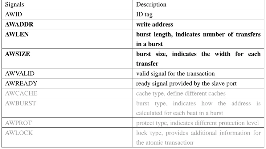
Table 3.2 Signal description for write address channel
Signals Description
AWID ID tag
AWADDR write address
AWLEN burst length, indicates number of transfers
in a burst
AWSIZE burst size, indicates the width for each
transfer
AWVALID valid signal for the transaction
AWREADY ready signal provided by the slave port
AWCACHE cache type, define different caches
AWBURST burst type, indicates how the address is calculated for each beat in a burst
AWPROT protect type, indicates different protection level AWLOCK lock type, provides additional information for
the atomic transaction
Table 3.2 shows the signals in the AW channel. The cache, burst, protect and lock types
are unnecessary since they specifies how to deal with transactions in different type of targets,
The AWADDR, AWLEN, AWSIZE have been already included in the TLM-2.0 generic
payload. As table 3.1 shows, AWADDR = Address, AWSIZE = Streaming width, AWLEN =
Data length/Streaming width.
The valid and ready signals are not needed in the payload in the TLM. In an RTL model,
both the transaction attributes and channel hand-shake signals (valid/ready) are implemented
as wire or reg variables in each AXI channel. And the transaction attributes is passed from
initiators to targets while the channel hand-shake signals are not. In a TLM, transactions are
aggregated in a class which is passed from initiators to targets. Thus we do not include the
channel hand-shake signals in the transaction class, but implement the hand-shake signals in
the interfaces.
We add the ID tag and AXI channel type identifier in the payload extension class which
will be introduced in chapter 4. The AR channel is the same as AW channel.
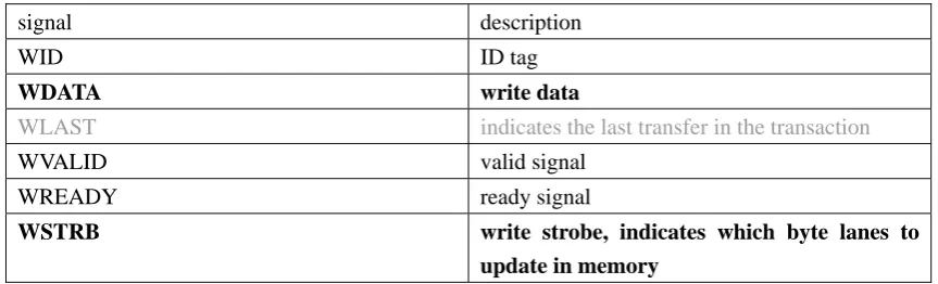
Table 3.3 Signal description for write data channel
signal description
WID ID tag
WDATA write data
WLAST indicates the last transfer in the transaction
WVALID valid signal
WREADY ready signal
WSTRB write strobe, indicates which byte lanes to
Table 3.3 shows the signals in W channel. The data is included in the default generic
payload type in TLM-2.0. And the write strobe is functional identical as byte enable array.
As a high-level model, TLM does not need the WLAST to indicate the last transfer
since we do not send multi-beat transactions in multiple cycles. The R channel is the same as
W channel.
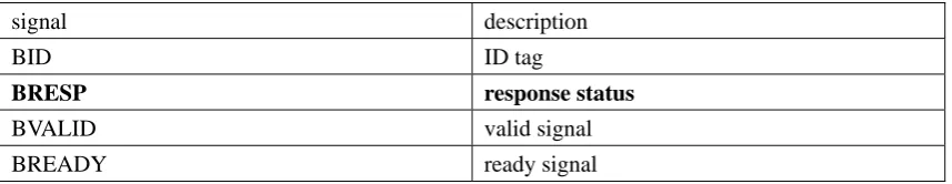
Table 3.4 Signal description for write response channel
signal description
BID ID tag
BRESP response status
BVALID valid signal
BREADY ready signal
Table 3.4 shows the signals in write response channel. The BRESP is the response
status to indicate if the transaction is success. Since the generic payload in TLM-2.0 has the
tlm_response_status member, we do not need to add an extra status member.
From Table 3.1-3.4, we could conclude that the default TLM-2.0 generic payload holds
nearly all the necessary features to implement the AXI protocol. What we need to add are the
ID tag and an AXI channel identifier to ensure the transaction will be forwarded to the
3.2
Router Structure
The router structure is one of the core contributions of this thesis. To deal with
multi-beat transaction and multiple requests, we use a full pipelined canonical router which
is simplified from [5].
3.2.1
Router structure and component
arbiter Crossbar block input_queu
e
input_queu
e
decoder
decoder 1
1
2
2
3
3
4
4
5
5
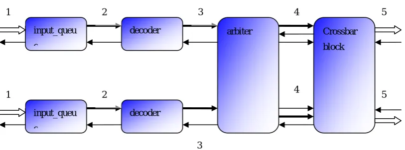
Fig 3.2 Four-stage-pipelined router structure
Fig 3.2 shows the pipeline structure for one AXI channel of the router. Each number
represents the signal that transfers from current block to the next one. The description of
those signals is listed below:
1: Incoming transactions and AXI ready signal (backward)
2: Transactions from the input_queue
3: generated request
5: transactions to send to the targets and AXI ready signal (backward)
This pipeline structure is identical for each AXI channel. We will describe the function
and implementation in SystemC for each stage.
Input Queue
The input queue is essentially a FIFO. Whenever the initiator sends a transaction to this
router, the input queue will put the pending transaction into the FIFO as long as the FIFO is
not full. In our model, there are four types of transactions: write request, write response, read
request, read response. The write response and read request are single-beat transactions
while the write request and read response could be multi-beat since they may contain data
blocks.
Trans-1 Trans-2
Trans-3
Addr 1 Addr 2
Addr 3
Fig 3.3 FIFO in the input queue stage
As Fig 3.3 shows, there are two FIFOs in the input queue stage. The address
we do not want to call the interface function every cycle to transfer a multi-beat transaction,
we forward the entire transaction at one time and wait for several cycles. In case of a
multi-beat transaction whose burst length is N, the ready signal is asserted to logic 1 again N
cycles later.
Decoder
A simple decoder is implemented to determine the destination of the transaction. Both
forward requests and backward requests need to be decoded. Different decoding
mechanisms are implemented in different channels. In the AW and AR channels, we simply
apply a dummy decoder that uses the MSB of the address to find out which target the
transaction should be forwarded to. In other words, the memory address mapping is fixed
and static. In the backward channels (read data/write response), decoders look at the ID tag
to identify the initiator #. More advanced routing mechanisms will be added to this design as
it is used to research different network-on-chip topologies. The decoder will pop out the
transaction from the FIFO and generate a request to the relative arbiter. Fig 3.4 shows the
REG
REG
Addr or ID
Port ID
Transaction Transacti Request
on Decode
logic
Fig 3.4 Schematic of the decoder at the register-transfer level
To model this behavior, we define a enumerate type implement a simple FSM (Finite
State Machine).
typedef enum { REQ_NULL = 0, REQ_WAIT, REQ_GRANT,
REQ_NOT_FINISHED } request_status;
This is the request status for all the pipeline stages. In decoder block, we do not need all
4 of these states. After initialization, the status is set to REQ_NULL. A status with
REQ_NULL indicates that the decoder should pop out the input queue and decode the
incoming transaction. Once the decoder generates a request, the status is set to REQ_WAIT
transaction blocks the traffic; and the decoder just holds under this condition.
Arbiter
The schematic of the arbiter is illustrated in Fig 3.5. The function of the arbiter is to
generate a winner from multiple pending requests. To simplify the problem, we use a
fixed-priority mechanism. Each initiator has a fixed priority. A request from high priority
initiator will be granted first in case of multiple pending requests. However, in multi-beat
transfer, one transaction cannot be interrupted after granted. Thus we still need a simple
FSM to control the arbiter.
Arbitrate logic
REG
REG REG
REG
Transaction Transaction
Transaction
Transaction Request 1
Request 2
Winner 1
Winner 2 Response
Fig 3.5 Schematic of the arbiter
We use “request_status”. The arbiter block will check the status of the decoder to see if
there is any pending request available. Then the arbiter reads all the requests for one target
port, grants the one with highest priority, modifies the status of the arbiter to REQ_GRANT,
REG
REG Transaction
Transaction Winner 1
Winner 2
Output 1
Output 2
Fig 3.6 Schematic of the crossbar stage
Crossbar
As Fig 3.5 shows, the crossbar block forwards the granted request to the relative target.
We need to consider the case of a multi-beat transaction in the write data channel and read
data channel. It takes several cycles to forward all the data in a multi-beat transaction. We
could send one piece of data to the target each clock cycle, but it would need to be
reassembled into one transaction and would slow down the simulation speed. Instead, we
mark two timing points for the data: the time of the first transfer and the time of the last
transfer. At the first point, the router forwards the entire transaction to the target. At the
second point, the crossbar modifies the crossbar status to REQ_NULL and begins to forward
the next transaction. This approach provides good interoperability. For a cycle-accurate
target, it could deal with the multi-beat transfer; for a loosely-timed or approximately-timed
at the second point.
Fig 3.7 FSM for crossbar block in the NoC router
The FSM is shown in Fig 3.7. The crossbar block reads the data length from the
transaction and maintains a counter to get the second timing point. The current transaction is
sent to the target in the REQ_GRANT status.
To simulate the 4-stage-pipeline structure, we execute each block in reverse order.
void pipeline(AXI_BUS_VAR_TYPE &AXI_channel, char direction){ crxbar(AXI_channel, direction);
}
Fig 3.1 shows the pipeline structure for one channel. Since different channels are
independent according to AXI protocol, we duplicate several pipeline() function to represent
different channels. The direction indicates that if the pipeline is a forward path or backward
path since there is a tiny difference between the two directions due to the number of port in
each direction.
3.2.2
Pipeline timing diagram
Some case studies are presented here to demonstrate the pipeline behavior. First, we
look at a router with only 1 master port and 1 slave port.
clock cycle
0 1 2 3 4 5
inputQ trans 1 trans 2-1 trans 2-2 trans 3 trans 4 trans 5 Decoder request 1 request 2 - request 3 request 4
Arbiter winner 1 winner 2 - winner 3
Crossbar trans 1 trans 2-1 trans 2-2
Fig 3.8 Timing diagram for the router with 1 master and 1 slave
Fig 3.8 shows the timing diagram for a one-master one-slave router. Assuming that
there are more than 5 transactions in the input queue, the timing diagram shows the pipeline
behavior clearly. Transaction 1 is single-beat, so we should not block the transfer.
Transaction 2 contains multiple transfers (as shown in Fig 3.3), after the crossbar stage
TLM, the “request_status” helps to implement the control flow.
clock 0 1 2 3 4 5
InputQ A InputQ B trans A-1-1 trans B-1-1 trans A-1-2 trans B-1-2 trans A-2-1 trans B-1-2 trans A-2-2 trans B-2-1 - trans B-2-1 - trans B-2-2 Decoder A Decoder B request A-1 request B-1 - request B-1 request A-2 - request A-2 - - request B-2
Arbiter winner A-1
- winner B-1 - winner B-1 - winner A-2 -
Crossbar trans A-1-1
-
trans A-1-2 -
trans B-1-1 -
Fig 3.9 Timing diagram for the router with traffic contention
In case of two initiators (A and B) sending transactions to the same target, the request
with higher priority will be granted first. In Fig 3.9, both initiator A and B send transactions
to the same target, and initiator A has higher priority. In cycle 2, request A-1 is granted, and
then the request B-1 is blocked by the arbiter. In cycle 4, since transaction A-1 is multi-beat,
CHAPTER 4
SYSTEM IMPELMENTATION
In this chapter, we will discuss how to build an interconnect system based on TLM-2.0.
We will introduce a simple bus model, to see how the basic protocol works in TLM-2.0.
Then we will see how to combine the approximately-timed model and cycle-accurate model
to form the hybrid TLM based on the TLM-2.0 basic protocol.
4.1
Simple bus system in TLM-2.0
4.1.1
Bus architecture and component
A simple bus system consists of initiators, targets, interconnect components, traffic
generators and memory blocks. Fig 4.1 shows different types of simple bus.
The simplest way to model a bus is to connect an initiator and a target together directly,
but this is used only in a point to point bus. To model a bus bridge, there are two alternatives:
model the bus bridge as an interconnect component or model the bus bridge as a
combination of initiator and target. An interconnect component just passes the point of the
transaction from the initiator to the target, which increases simulation speed. The transaction
bridge gives more flexibility since the transaction is changeable in the bridge, but reduces
the simulation speed.
Since only one protocol is applied in our model, we prefer the interconnect component
to achieve higher simulation speed.
traffic generator
traffic generator
initiator
initiator
Router target with
memory
target with memory
Fig 4.2 Block diagram for a 4-phase AT bus
Fig 4.2 shows the block diagram of the approximately-timed bus model that comes with
the TLM-2.0 standard. The system has 2 initiators and 2 targets. The traffic generator and
traffic generator and forwards it to the bus through a non-blocking channel. The bus block
performs simple decode and arbitrate functions forwards the transaction to the right target
through a non-blocking channel. A target receives the transaction from the bus and forwards
to the memory block.
Interconnect component
The structure of the simple bus router interconnect component from the TLM-2.0
standard is illustrated in Fig 4.3
SC_THREAD (request)
SC_THREAD (response) PEQ
PEQ
Fig 4.3 Router structure in TLM-2.0 SimpleBusAT.h
All transactions received by the target socket of the bus will be sent into the PEQ
(Payload Event Queue). The PEQ includes a pointer to the transaction entity and an event
with notified time. The main process (SC_THREAD) will get the next transaction from the
PEQ if the notified timing point has been past. The timing point helps to set the transaction
delay between the initiator and the bus. The pseudo code for the process is: SC_thread(request) {
while(true) {
get pending request from the queue; decode, find destination port;
forward the pending request to the relative target; get response, change transaction phase;
tell initiator the result if necessary; erase the transaction if completed; }
}
Target and memory block
The structure of the target and memory block from TLM-2.0 standard is illustrated in
Fig 4.4. One advantage of this bus structure is that it provides a simple memory block.
PEQ
END_REQ_THREAD
get delay
Memory
BEG_RESP_THREAD PEQ Trans. for sent
W/R
Fig 4.4 Block diagram for target with memory
The target uses 2 PEQs to synchronize with bus block. The memory access delay and
4.2
AXI bus model based on TLM-2.0
The TLM-2.0 simple bus gives a good framework to our bus system. To simplify code
development, we base our Hybrid TLM on that model and maintain interoperability with it.
4.2.1
Hybrid TLM
One problem of the TLM-2.0 standard is that it currently does not support
cycle-accurate modeling. We want to implement a cycle-accurate model because:
1. It best describes the hardware structure.
2. It gives accurate transaction delays in the presence of complex traffic congestion.
The approximately-timed model could run much faster than CA model. To get better
performance, we divide the model into 2 parts: the router part which needs CA model to
make precise delay estimation, and the other peripheral parts, which use the original AT
clock
traffic generator
traffic generator
initiator
initiator
Router target with
memory
target with memory
approximately-timed approximately-timcycle-accurate ed
Fig 4.5 Hybrid TLM
A clock signal is applied to the interconnect component. The functions inside the router
will be executed every cycle to maintain a cycle-accurate model. But the inter-module
process still works in approximately-timed mode. Essentially, this model is
approximately-timed, but the router block has a SC_METHOD running every clock cycle.
Channel Identifi-cation
SC_METHOD clock
AW_channel
AR_channel
R_channel
B_channel
Channel Identifi-cation
Monitor block
Fig 4.6 Block diagram of the router in TLM
Fig 4.6 shows the block diagram of the router. The router has one SC_METHOD
process which is sensitive to the clock rising edge to handle the request. There are 4
independent channels in the process, each of which is a pipeline structure as Fig 3.1. Once
the transaction is sent to the bus from the initiator, it will be processed as follows:
1. The initiator calls the socket function “nb_transport_fw()” to send the transaction to
the socket of the router.
2. The socket passes the transaction to a “channel identification” function in which the
pending transaction is stored temporary and a valid signal is asserted for the correct AXI
channel.
3. After clock rising edge, the SC_METHOD reads the pending transactions and sends
4. The transaction is processed in the SC_METHOD for several cycles and then the
SC_METHOD will call the socket function “nb_transport_fw()” to send the transaction to
the target socket.
In the case of multiple incoming transactions, the socket function “nb_transport_fw()”
will be called multiple times by initiators, and all the transactions will be stored. After clock
rising edge, all the transactions will be sent into relative input queues. If more than one
transaction are forwarded from the SC_METHOD to the target socket in the same cycle,
multiple socket function calls occurs, and the target will receive multiple transactions. Since
the target is not cycle-accurate and cannot process parallel transaction, it will put all
incoming transactions in a queue, and processes them one by one.
The monitor block gets the internal signal for each pipeline stage in the METHOD, and
let me view the wave form in QuestaSim.
Initiator and traffic generator
One important issue here is the extension of the generic payload. To implement the AXI
protocol, some extension is needed. An extension is a user-defined class including extra
attributes (memory variables) and methods. The TLM-2.0 generic payload has an extension
pointer to a user defined structure. This pointer is NULL if no extension is defined. In our
First is the AXI_channel_type. There are 5 independent channels in the router but only
1 channel for the inter-module transaction. So a mechanism of channel identification is
applied in the router to forward the transaction to the right channel. The AXI_channel_type
is determined by the traffic generator and the target.
Second is the ID tag of the transaction. The ID tag is not necessary right now for the
single-hop NoC, but might be useful for a multi-hop network since the ID tag records the
initiators on the routing path.
Target with memory
There are a few changes in the target module including AXI_channel_type setting and
CA-AT interface. Notice that the router is CA and the target-and-memory block is AT. A
multi-beat transaction takes several clock cycles to be forwarded in a cycle-accurate model.
To avoid sending one piece of data cycle-by-cycle and slowing the simulation with repeated
function calls, we send the entire transaction to the target at the first cycle to increase the
simulation speed. Hence the target needs to calculate the “accept delay” according to the
burst length.
4.2.2
Protocol modification
TLM-2.0 uses transaction phases to implement a basic protocol. There are 4 phases to
transition is: BEGIN_REQ -> END_REQ -> BEGIN_RESP -> END_RESP. One or two
phase(s) could be ignored in certain kinds of protocols.
Initiator 1,7 SimpleBusAT 2,8 Target
3,5 4,6
Fig 4.7 Phase transition sequence in a 4-phase protocol
The above figure shows how a 4-phase transaction is implemented in AT_4-phase bus.
The arrow represents a forward or backward channel and the number represents the
sequence of method/function call.
1: The initiator sends transaction to the router with “BEGIN_REQ” phase, and waits for
“END_REQ” phase.
2: The router forwards the transaction to the target with “BEGIN_REQ” phase, and
waits for “END_REQ” phase from the target.
3: The target receives the transaction and send back “END_REQ” to the router, and
forwards the transaction to the memory.
4: The router sends back “END_REQ” to the initiator; the initiator prepares to send
next transaction.
5: The target sends back the transaction with “BEGIN_RESP” phase to the router.
7: The initiator sends “END_RESP” to the router, router return “TLM_COMPLETE” to
the initiator to identify the completion of that transaction and remove the transaction from
the queue.
8: The router forward “END_RESP” to the target and release the transaction entity, the
target is able to send another response.
In our router module, we need to apply the AXI protocol which has a valid-ready
channel handshake. A valid signal is asserted with the corresponding non-blocking function
call. The default value of the ready signal is 1. When a new transaction is received by the
target socket, the ready signal is set to 0. It is set to 1 again with the response of
END_REQ/END_RESP. In other words, the BEGIN_REQ or BEGIN_RESP phase
represents the AXI valid signal, and the END_REQ or END_RESP phase represents the AXI
ready signal.
The original transition sequence ensures that the END_REQ is sent back to the initiator
after the target receives the transaction. In a fully pipelined router, the initiator should be
able to send the next transaction as long as the router input queue is not full. So we modify
Initiator 1,8 Router Target
2,7
3,6
4,5 valid
valid ready
ready
Fig 4.8 Phase transition sequence in AXI bus model
1: The initiator sends a transition to the router with BEGIN_REQ phase, AXI valid
signal is asserted to 1.
2: The router receives the transaction and sends back a response with END_REQ phase
if the input queue is not full. AXI ready signal is set to 0 until the completion of the burst in
case of multi-beat transfer. Then the initiator is capable to send another transaction.
3: The router forwards the transaction to the target with BEGIN_REQ and asserts the
AXI valid signal.
4: The target sends back END_REQ, the AXI ready signal will be set to 1 after the
entire transaction is completed.
5: The target sends BEGIN_RESP to the router and asserts the AXI valid signal to 1.
6: The router sends back END_RESP to the target.
7: The router forwards the transaction to the initiator with BEGIN_RESP phase.
By making above modification, we are able to apply the AXI protocol based on the
4-phase protocol in TLM-2.0. The extra handshake signals are defined and used in the router
module to keep the interoperability.
4.3
Simulation result for TLM and RTL model
To show that the transaction-level model of the AXI router is cycle-accurate with
respect to the RTL model, we will demonstrate some simulation results of a common
test-case. While this does not verify complete cycle accuracy, it does demonstrate complete
agreement for the test case used so far.
Single-beat transaction
The single-beat transaction example shows the pipeline feature and the crossbar feature
in a 2-initiator-2-target system.
Stimulus:
Initiator 1: 3 transactions, high priority, destination: target 1
Initiator 2: 3 transactions, low priority, destination: target 2
cycle behavior
0 Initiator 1 and 2 send trans-A1 and trans-B1
1 trans-A1 and trans-B1 are sent to the input queue
2 request-A1 and request-B1 are generated, trans-A2 and trans-B2 are sent to input queue
3 request-A1 and request-B1 are granted, request-A2 and request-B2 are generated, trans-A3 and trans-B3 are sent to input queue
4 trans-A1 and trans-B1 are forwarded to target 1 and 2. request-A2 and request-B2 are granted, request-A3 and request-B3 are generated
5 trans-A2 and trans-B2 are forwarded to target 1 and 2. request-A3 and request-B3 are granted.
6 trans-A3 and trans-B3 are forwarded to target 1 and 2. All transactions are complete
Simulation result for TLM in QuestaSim v6.3:
Fig 4.9 Simulation result for TLM in case of single-beat transfers
Simulation result for RTL model in QuestaSim v6.3:
Fig 4.9 and Fig 4.10 shows the simulation result in AW channel for TLM and RTL
model. In the TLM, the signal “ADDR_crxbar” is the output of the router while in RTL
model, the signal “AWADDR_OUT_1/2” is the output. In the TLM, we do not really build
SystemC channels between pipeline stages but only C++ struct arrays. But the simulation
result shows that the TLM router is cycle-accurate and the value of internal registers is
identical to which in RTL model.
Multi-beat transaction
The following example shows the multi-beat condition in a 2-initiator-2-target system
with traffic contention.
Stimulus:
Initiator 1: 2 transactions, high priority.
Initiator 2: 4 transactions, low priority.
For all the transactions, the destination is target 1 and the burst length is 4.
All the initiators send the transactions continuously. In case of multi-beat transaction
with a burst length equals to 4, the next transaction will be sent 4 cycles later.
cycle behavior
0 Initiator 1 sends trans-A1, initiator 2 sends trans-B1
1 Both of the transactions are transferred to the input queue, but not complete. 2 Decoder generates request-A1 and request-B1
3 A1 is granted by the arbiter. arbiter generates winner-A1
4 A1 is sent to the target. Request B1 is granted, arbiter generates winner-B1. trans-A1 and B1 are sent complete.
5 Initiator 1 and 2 send trans-A2 and B2 to the input queue. 6 request-A2 and request-B2 are generated.
7 trans-A1 is sent complete to target 1.
8 trans-B1 is sent to target 1, request-A2 is granted. A2 and B2 are sent complete. 9 Initiator 2 sends trans-B3 to the input queue
11 B1 is completely forwarded to target 1.
12 A2 is sent to target 1. request-B2 is granted, request-B3 is generated. trans-B3 is received completely by the input queue.
13 trans-B4 is sent to the input queue 15 trans-A2 is sent complete to target 1
16 trans-B2 start being to sent to target 1, request-B3 is granted, request-B4 is generated 19 trans-B2 is completely forwarded to target 1
20 trans-B3 start begin to sent to target 1, request-B4 is granted. no pending request generated
23 trans-B3 is completely forwarded to target 1 24 trans-B4 start begin to sent to target 1
27 trans-B4 is completely forwarded to target 1. All transactions are sent complete.
Simulation result for TLM in QuestaSim v6.3:
Simulation result for RTL model in QuestaSim v6.3:
Fig 4.12 Simulation result for RTL model in case of multi-beat transfers
The simulation result for the RTL model and TLM are still identical in case of
multi-beat transaction from Fig 4.11 and 4.12.
4.4
Performance analysis
We compare the simulation speed among our hybrid model, the RTL model and the
original approximately-timed TLM in the TLM-2.0 as Fig 4.13 shows. The
approximately-timed model and hybrid model are identical except the router part. The
hybrid model acts as we introduced before. And in the approximately-timed model, the
router does not do any arbitrating work. It stores the incoming transactions in a queue and
forwards them to the right targets. The RTL model contains a 4-channel router as we
described in Chap. 3, and we send the same transaction directly to the router. In the
target will send back response transactions via write response channel (B channel). And we
do not have a target in the RTL model, so only one channel is used in that model.
Initiators
Cycle-accurate router
Targets
Approximately-timed router
(a) AT-TLM and Hybrid TLM
Stimulus RTL router
(b) RTL model
Fig 4.13 Block diagram for the test bench of the three types of model
We run the simulation to send 500 transactions for each initiator (1000 transactions
total). Each transaction has 4 beats. The hybrid model and the RTL model take the same
cycles to finish the simulation (4000 cycles), while the original approximately-timed TLM
runs less cycles.
Table 4.1 Simulation time measurement
RTL model Original TLM Hybrid TLM
Wall time (sec) 0.2880 0.02951 0.04728
CPU time (sec) 0.2809 0.02399 0.04099
Speed Up from CPU time
1 shows the simulation result. All the models run in QuestaSim v6.3. We use
“sim
Table 4.
stats” command to record the CPU time and wall time. Wall time is the amount of time
taken by a computer to complete a task. It consists of CPU time, I/O time and
communication channel delay. We calculate the speed up of TLM from the CPU time.
RTL TLM
CPUtime
speedup= . The difference between the Original TLM and Hybrid TLM is
curate router in the Hybrid TLM. A SC_METHOD based
cycle-accurate module will slow down the simulation speed by 30%, but provides more
accurate result and the ability to handle complex traffic contention. CPUtime
that we have a cycle-ac
he speed up of the TLM compared to the RTL model is not very high because the RTL
mod
his chapter has demonstrated a TLM that is cycle-accurate with respect to an RTL
mod T
el is just the router part while the TLM contains initiators, targets and memory blocks. If
we develop the entire bus system for the RTL model, the simulation time of RTL model will
increase further more.
T
el. This model is ideal to use in estimating accurate latency in cycle-counts, especially
CHAPTER 5
CONCLUSTION AND FUTURE WORK
5.1
Conclusion
This thesis has presented a transaction-level model for a simple on-chip interconnect. It
also describes a cycle-accurate full-pipelined router structure. Based on TLM-2.0 standard,
this model keeps good interoperability. The simulation results of the TLM and RTL shows
the accuracy of our model.
One important feature in our model is the hybrid timing mechanism. In the router
module, we use SC_METHOD to simulate a pipeline structure and keep cycle-accurate. This
kind of cycle-accurate model will produce the latency automatically in cycle count, which
makes it easy to calculate the throughput. As the network grows bigger, the traditional
approximately-timed model cannot deal with complex traffic, but our model can. Another
feature is the interoperability of the protocol. We built an AXI protocol based on the basic
4-phase protocol in TLM-2.0. Hence other modules could be connected to our model as long
as it complies with TLM-2.0 standard. That increases the flexibility and reusability of our
5.2
Future work
One goal of this model is to provide an approach to explore the design space of NoCs at
system level. With this model, designers could connect the AXI routers together to form
network-on-chips with different structures and analyze the performance.
This model also provides a basic framework for transaction-level model of NoCs.
REFERRENCES
[1] Thorsten et al., System Design with SystemC, Kluwer Academic Publisher, 2002.
[2] The Open SystemC Initiative (OSCI), “Transaction Level Model Standard” v1.0, 2005. Available: http://www.systemc.org
[3] Adam Donlin, “Transaction Level Modeling: Flows and Use Models,” Int’l Conf. Hardware/Software Codesign and system synthesis, pp. 75-80, 2004.
[4] The Open SystemC Initiative (OSCI), “Transaction Level Model Standard” v2.0, 2008. Available: http://www.systemc.org
[5] Kim et al., “Microarchitecture of a high radix router,” Proc. 32nd Int’l Symp. Compute Architecture, pp. 420–431, 2005.
[6] ARM inc., “AMBA AXI protocol specification,” v1.0, Available:
http://www.arm.com/products/solutions/axi_spec.html
[7] Wayne Wolf et al., “On-chip networks: A scalable, communication-centric embedded system design paradigm,” Proc. 17th Int’l Conf. VLSI Design, pp. 845-851, 2004.
[8] H. Hua, et al. “Exploring compromises among timing, power and temperature in three-dimensional integrated circuits,” ACM/IEEE Design Automation Conf., pp. 997-1002, 2006.
[9] Sudeep Pasricha, Nikil Dutt, Mohamed Ben-Romdhane, “Using TLM for Exploring Bus-based SoC Communication Architectures,” Proc. 16th Int’l Conf. Application-Specific Systems, Architecture and Processors, 2005.
[10]M. Caldari et al., “Transaction-Level Models for AMBA Bus Architecture Using SystemC 2.0,” Proc. Design, Automation and Test in Europe, pp. 26-31, 2003.
[11]Hye-On Jang et al., “High-Level System Modeling and Architecture Exploration with SystemC on a Network SoC: S3C2510 Case Study,” Proc. Design, Automation and Test in Europe, vol. 1, pp. 538-543, Feb. 2004.
[13]Gunar Schirner, Rainer Dömer, “Result-Oriented Modeling—A Novel Technique for Fast and Accurate TLM,” IEEE Trans. Computer-Aided Design of Integrated Circuit and Systems, vol. 26, no. 9, Sep. 2007.
Appendix A
Code change list
//---traffic_generator.cpp---
// the traffic generator generates write or read request transactions, and sends them to the // initiators. All attributes of generic payload are set up here. If AXI feature is used, the extension // class needs to be set here. The extension class is declared in the traffic_generator and is
// connected to the transaction class. Memory space are allocated to the transactions and the // pointers are passed among modules
//
//---
--- // generate write request. Set the attributes for each transaction
transaction_ptr->set_command ( tlm::TLM_WRITE_COMMAND ); transaction_ptr->set_address ( mem_address );
transaction_ptr->set_data_length ( m_txn_data_size ); transaction_ptr->set_streaming_width ( m_txn_data_size ); transaction_ptr->set_response_status ( tlm::TLM_INCOMPLETE_RESPONSE );
#if ( defined ( USING_EXTENSION_OPTIONAL ) )
// set the extension, generate ID tag and channel type. The extension is optional according to // TLM-2.0. The macro “USING_EXTENSION_OPTIONAL” controls it.
AXI_extension *extension_pointer; // extension pointer
extension_pointer = new AXI_extension; sc_dt::sc_uint<AWID_WIDTH> AWID = 0;
AXI_channel_type trans_channel = AW_CHN;
AWID = sc_dt::sc_uint<AWID_WIDTH>((m_ID << AWID_WIDTH-1) + j); extension_pointer->set_AWID(AWID);
extension_pointer->set_channel_type(AW_CHN);
// register the extension
transaction_ptr->set_extension ( extension_pointer );
//generate read request
transaction_ptr->set_command ( tlm::TLM_READ_COMMAND ); transaction_ptr->set_address ( mem_address );
transaction_ptr->set_data_length ( m_txn_data_size ); transaction_ptr->set_streaming_width ( m_txn_data_size ); transaction_ptr->set_response_status ( tlm::TLM_INCOMPLETE_RESPONSE );
#if ( defined ( USING_EXTENSION_OPTIONAL ) )
// set the extension
AXI_extension *extension_pointer; // extension pointer extension_pointer = new AXI_extension;
sc_dt::sc_uint<AWID_WIDTH> AWID = 0; AXI_channel_type trans_channel = AR_CHN;
AWID = sc_dt::sc_uint<AWID_WIDTH>((m_ID << AWID_WIDTH-1) + i); extension_pointer->set_AWID(AWID);
extension_pointer->set_channel_type(trans_channel);
// register the extension
transaction_ptr->set_extension ( extension_pointer );
#endif /* USING_EXTENSION_OPTIONAL */
//---SimpleBusAT.h---
// the implementation of the router. Contains socket methods and pipeline functions (input queue, // decoder, arbiter, crossbar). It is a 2-input-2-output router which connected to initiators and // targets via sockets. Registered socket methods are implemented here. As a user-defined socket
// method, it forwards the incoming transaction to the relative AXI channel, maintains a // valid-ready handshake mechanism and help synchronize modules. The pipeline functions
// simulate the behavior of the cycle-accurate router. This router runs every clock cycle by // executing a SC_METHOD process.
//
//---
--- public:
#if ( defined(USING_MONITOR_OPTIONAL))
sc_core::sc_port <AXI_monitor_if > monitor_port;
#endif
public:
SC_HAS_PROCESS(SimpleBusAT);
SimpleBusAT(sc_core::sc_module_name name) : sc_core::sc_module(name),
{
for (unsigned int i = 0; i < NR_OF_INITIATORS; ++i) {
target_socket[i].register_nb_transport_fw(this, &SimpleBusAT::initiatorNBTransport, i);
target_socket[i].register_transport_dbg(this, &SimpleBusAT::transportDebug, i); target_socket[i].register_get_direct_mem_ptr(this, &SimpleBusAT::getDMIPointer, i);
}
for (unsigned int i = 0; i < NR_OF_TARGETS; ++i) {
initiator_socket[i].register_nb_transport_bw(this, &SimpleBusAT::targetNBTransport, i);
initiator_socket[i].register_invalidate_direct_mem_ptr(this, &SimpleBusAT::invalidateDMIPointers, i);
}
num_initiator = NR_OF_INITIATORS; num_target = NR_OF_TARGETS;
init_reg();
SC_METHOD(ForwardPath);
sensitive_pos << clock;
} //
// AT protocol //
void ForwardPath(){
pipeline(AW_channel, 'f');
monitor_port->chn_monitor(AW_channel); #endif
pipeline(RD_channel, 'b');
}
//
// interface methods //
sync_enum_type initiatorNBTransport(int initiator_id,
transaction_type& trans, phase_type& phase, sc_core::sc_time& t) {
if (phase == tlm::BEGIN_REQ) { trans.acquire();
//addPendingTransaction(trans, 0, initiator_id);
#if ( defined ( USING_EXTENSION_OPTIONAL ) ) //identify AXI channel
AXI_extension *extension_pointer; AXI_channel_type channel_type; trans.get_extension(extension_pointer);
channel_type = extension_pointer->get_channel_type();
switch (channel_type)
{
case AW_CHN: {
AW_channel.pending_payload_ptr[initiator_id] = &trans; AW_channel.in_valid[initiator_id] = 1;
break; }
case AR_CHN:
{ //should be AR_channel that is not implemented right now AW_channel.pending_payload_ptr[initiator_id] = &trans;
AW_channel.in_valid[initiator_id] = 1; break;
}
{
std::cout<< "ERROR: '"<< name()
<< "':Illegal AXI_channel received from initiator " <<initiator_id << std::endl;
assert(false); exit(1); }
default: {
std::cout<< "ERROR: '"<< name()
<< "Unknown AXI_channel from initiator " << initiator_id << std::endl; assert(false); exit(1);
} }
#endif /* USING_EXTENSION_OPTIONAL */
} else if (phase == tlm::END_RESP) { mEndResponseEvent.notify(t); return tlm::TLM_COMPLETED;
} else {
std::cout << "ERROR: '" << name()
<< "': Illegal phase received from initiator." << std::endl; assert(false); exit(1);
}
return tlm::TLM_ACCEPTED; }
sync_enum_type targetNBTransport(int portId,
transaction_type& trans, phase_type& phase, sc_core::sc_time& t) {
if (phase != tlm::END_REQ && phase != tlm::BEGIN_RESP) { std::cout << "ERROR: '" << name()
<< "': Illegal phase received from target." << std::endl; assert(false); exit(1);
}
//change by Jianchen Hu
if(phase == tlm::END_REQ)
mEndRequestEvent.notify(t); if (phase == tlm::BEGIN_RESP) {
#if ( defined (USING_EXTENSION_OPTIONAL) )
AXI_extension *extension_pointer; AXI_channel_type channel_type;
trans.get_extension(extension_pointer);
channel_type = extension_pointer->get_channel_type(); switch (channel_type)
{
case(R_CHN):
{
RD_channel.pending_payload_ptr[portId] = &trans; RD_channel.in_valid[portId] = 1;
break; }
case(B_CHN): {
RD_channel.pending_payload_ptr[portId] = &trans;
RD_channel.in_valid[portId] = 1; break;
}
case(AW_CHN): case(AR_CHN):
{
std::cout<< "ERROR: '"<< name()
<< "':Illegal AXI_channel received from target " <<portId << std::endl; assert(false); exit(1);
break;
} default:
{
std::cout<< "ERROR: '"<< name()
<< "Unknown AXI_channel from target " << portId << std::endl;
assert(false); exit(1); }
}
#endif /* USING_EXTENSION_OPTIONAL */
return tlm::TLM_ACCEPTED; }
private:
void addPendingTransaction(transaction_type& trans, initiator_socket_type* to, int initiatorId)
{
const ConnectionInfo info = { &target_socket[initiatorId], to };
assert(mPendingTransactions.find(&trans) == mPendingTransactions.end()); mPendingTransactions[&trans] = info;
}
private:
struct ConnectionInfo { target_socket_type* from; initiator_socket_type* to; };
typedef std::map<transaction_type*, ConnectionInfo> PendingTransactions; typedef typename PendingTransactions::iterator PendingTransactionsIterator;
typedef typename PendingTransactions::const_iterator PendingTransactionsConstIterator;
private: PendingTransactions mPendingTransactions; tlm_utils::peq_with_get<transaction_type> mRequestPEQ0; tlm_utils::peq_with_get<transaction_type> mRequestPEQ1; sc_core::sc_event mBeginRequestEvent; sc_core::sc_event mEndRequestEvent; tlm_utils::peq_with_get<transaction_type> mResponsePEQ; sc_core::sc_event mBeginResponseEvent; sc_core::sc_event mEndResponseEvent; int num_initiator; int num_target;
AXI_BUS_VAR_TYPE AW_channel, RD_channel;
arbitrate(AXI_channel, direction); decode(AXI_channel,direction); input_queue(AXI_channel,direction);
}
void init_reg(){ int i;
AW_channel.Req_inputQ = new virtual_fifo[NR_OF_INITIATORS];
AW_channel.pending_request = new AXI_REQ_TYPE[NR_OF_INITIATORS]; AW_channel.arb_winner = new AXI_WINNER_TYPE[NR_OF_TARGETS]; AW_channel.Trans_for_sent = new CRXBAR_TYPE[NR_OF_TARGETS]; AW_channel.pending_payload_ptr = new gp_ptr[NR_OF_INITIATORS]; AW_channel.in_valid = new int[NR_OF_INITIATORS];
AW_channel.out_ready = new int[NR_OF_TARGETS];
AW_channel.input_length = new unsigned int[NR_OF_INITIATORS]; AW_channel.priority_table = new short[NR_OF_INITIATORS]; AW_channel.winner_table = new short[NR_OF_TARGETS]; RD_channel.Req_inputQ = new virtual_fifo[NR_OF_TARGETS];
RD_channel.pending_request = new AXI_REQ_TYPE[NR_OF_TARGETS]; RD_channel.arb_winner = new AXI_WINNER_TYPE[NR_OF_INITIATORS]; RD_channel.Trans_for_sent = new CRXBAR_TYPE[NR_OF_INITIATORS]; RD_channel.pending_payload_ptr = new gp_ptr[NR_OF_TARGETS]; RD_channel.in_valid = new int[NR_OF_TARGETS];
RD_channel.out_ready = new int[NR_OF_INITIATORS];
RD_channel.input_length = new unsigned int[NR_OF_TARGETS]; RD_channel.priority_table = new short[NR_OF_TARGETS]; RD_channel.winner_table = new short[NR_OF_INITIATORS];
for(i=0;i<num_initiator;i++){
AW_channel.pending_request[i].status = REQ_NULL;
AW_channel.pending_request[i].trans_ptr = new transaction_type; AW_channel.pending_request[i].destination = 0;
AW_channel.pending_request[i].dummy_count = 0; AW_channel.in_valid[i] = 0;
AW_channel.input_length[i] = 0;
RD_channel.arb_winner[i].status = REQ_NULL;
RD_channel.arb_winner[i].trans_ptr = new transaction_type; RD_channel.Trans_for_sent[i].status = REQ_NULL; RD_channel.Trans_for_sent[i].length = 0;
RD_channel.out_ready[i] = 1; AW_channel.priority_table[i] = i; RD_channel.winner_table[i] = -1;
}
for(i=0;i<num_target;i++){
AW_channel.arb_winner[i].status = REQ_NULL;
AW_channel.arb_winner[i].trans_ptr = new transaction_type; AW_channel.Trans_for_sent[i].status = REQ_NULL; AW_channel.Trans_for_sent[i].length = 0;
AW_channel.Trans_for_sent[i].trans_ptr = new transaction_type; AW_channel.Trans_for_sent[i].source = -1;
AW_channel.out_ready[i] = 1;
RD_channel.pending_request[i].status = REQ_NULL; RD_channel.pending_request[i].trans_ptr = new transaction_type; RD_channel.pending_request[i].destination = 0;
RD_channel.pending_request[i].dummy_count = 0; RD_channel.in_valid[i] = 0;
RD_channel.input_length[i] = 0; AW_channel.winner_table[i] = -1; RD_channel.priority_table[i] = i;
} }
void input_queue(AXI_BUS_VAR_TYPE &AXI_channel, char direction){ int i;
int range = 0;
transaction_type *trans;
AXI_extension *extension_pointer; AXI_channel_type channel;
sc_core::sc_time t = sc_core::SC_ZERO_TIME; if(direction == 'f')
range = num_initiator;
else range = num_target; for(i=0;i<range;i++){
if((AXI_channel.Req_inputQ[i].fifo_free()>0)&&(AXI_channel.in_valid[i] == 1)){ trans = AXI_channel.pending_payload_ptr[i];
AXI_channel.in_valid[i] = 0;
![Fig 2.2 TLM abstraction levels [3]](https://thumb-us.123doks.com/thumbv2/123dok_us/1765397.1227046/13.595.233.372.76.206/fig-tlm-abstraction-levels.webp)
![Fig 2.3 Applications for different coding styles [4]](https://thumb-us.123doks.com/thumbv2/123dok_us/1765397.1227046/14.595.125.484.268.535/fig-applications-for-different-coding-styles.webp)
![Fig 2.4 TLM-2.0 architecture [4]](https://thumb-us.123doks.com/thumbv2/123dok_us/1765397.1227046/16.595.114.521.318.625/fig-tlm-architecture.webp)
![Fig 3.1 channel handshake mechanism [6]](https://thumb-us.123doks.com/thumbv2/123dok_us/1765397.1227046/19.595.98.448.301.418/fig-channel-handshake-mechanism.webp)
![Table 3.1 attributes in TLM-2.0 generic payload [4]](https://thumb-us.123doks.com/thumbv2/123dok_us/1765397.1227046/20.595.81.513.333.656/table-attributes-tlm-generic-payload.webp)