DOI: http://dx.doi.org/10.26483/ijarcs.v8i7.4310
Volume 8, No. 7, July – August 2017
International Journal of Advanced Research in Computer Science
RESEARCH PAPER
Available Online at www.ijarcs.info
ISSN No. 0976-5697 ISSN No. 0976-5697
PERFORMANCE EVALUATION OF 8 CHANNELS DWDM-PON NETWORK
UNDER DIVERSE CONDITIONS
Vishal Sharma
Research Scholar (M Tech) DAVIET, Jalandhar
Love Kumar
DAVIET, Jalandhar India
Abstract: This paper presents the performance evaluation of 8 channels (8X10 Gbps in downlink, 8X5Gbps in uplink) bidirectional DWDM-PON based network. The result demonstrates that at 10Gbps data rate (downstream), the bit error rate (BER) for user 1 & 8 (randomly selected) are 3.16e-14 and 1.57e-10, respectively. Similarly, at 5Gbps data rate (upstream), the BER for user 1 & 8 are 1.66e-20 and 2.331e-09, respectively. The QAM line coding has been proved to be the optimum format for downstream, whereas CRZ modulation format is optimum for upstream in the designed system. The impact of various design parameters and impairments has also been considered during performance optimization
Keywords: Dense Wavelength Division Multiplexing (DWDM); Passive Optical Network; Optical Network Unit (ONU); Optical Line Terminal; DWDM-PON
1.INTRODUCTION
In the modern world, the demand of fast and cost effective communication system is required. Services like high speed Internet and broadband access have become an inseparable part of human society. The data traffic has risen tremendously over already existing communication system and customer based requested services like voice, video, High Definition TV etc. are continued to increase [1] The higher demand of broadband around the globe significantly makes service provider to provide services that are bandwidth intensive and which support many user [ 2,3]. Now, it is a challenge for service providers to provide best qualities of service to fulfill the demand of customers. Passive Optical Network seems to be a key technology that provides multiple services to users and make different architectures to effectively use bandwidth of fiber optical [4,5]. PONs provides cost effective solution [6]. WDM-PON emerged as useful technique to use the bandwidth effectively. It plays a critical role for multiservice and multicasting because of increased bandwidth facility. WDM PON is being widely used by the Korean telecom to provide commercial multiple services to end users [7]. Passive optical networks (PONs) are used as a cost effective method for sharing fiber infrastructure to business premises, curb and home etc. The PON system uses the passive components, which potentially reduces the cost and maintenance since it is point to multi point transport network. PON has several advantages such as fiber data rates up to 10 Gbits and passive power splitters which can be installed anywhere. Using upstream and downstream the PONs are served bi- directionally [8]. Research is going on for carrying multiple applications such as subcarrier multiplexing, OFDM, carrier reuse, wavelength reuse and data rates for extended reach [9]. An extensive research has been undergoing in WDM-PONs for different applications. A PON consist of an optical line terminal (OLT) at the service providers central office (CO) and a number of optical network units (ONU) or optical network terminals (ONTs), near end users. A PON reduces the amount of fiber
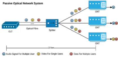
[image:1.595.331.532.395.493.2]and central office equipments as compared with point to point architectures. A passive optical network is a form of fiber optics access network which provide high bandwidth. The figure-1 depicts the various components used in the architecture Passive Optical Network (PON).
Figure 1. Architecture of PON
Initially, passive type optical network were developed during 1980’s . This type of optical network use passive components, which reduces the maintenance charges as well as cost since,it is a point to many point transport network
A. WDM-PON
operates at distance beyond 20 Km and provide data rates in the order of Gbits/sec due to its end to end fiber infrastructure. Due to less usage of the active components in PONs provides cost advantage since power and maintenance are one of the main cost factors for the local exchange
Figure 2 WDM PON architecture
Although the PON is a significant step towards providing broadband access to the end user, it is not very scalable. Since the basic form of PON employs only a single optical channel, the available bandwidth is limited to the maximum bit rate of an optical transceiver, which, under current technology is 1 Gbps. The deployment cost of laying fiber in the access network being high, it is important to consider technologies which may help scale the PON capacity in future. Many telecom operators are considering deploying PONs using a Fiber to-the-X(FTTX) model to support converged Internet Protocol (IP) video, voice, and data services defined as “triple-play” at a cheaper subscription cost than the cumulative of the above services deployed separately[10]. Although the PON provides higher bandwidth than traditional copper based access networks, there exists the need for further increasing the bandwidth of the PON by employing Wavelength Division Multiplexing (WDM) so that multiple wavelengths may be supported in either or both upstream and downstream directions. Such a PON is known as a WDM-PON [11]
A. DWDM PON
Dense wavelength division multiplexing type passive optical network is a upgraded version of WDM-PON in which channel spacing is very less. In DWDM channel spacing among signal is less so that more signals can be sent to end users. This type of Passive optical network increases the channel capacity and bit rate. The DWDM-PON architecture remains same except channel spacing as of WDM PON. In DWDM PON the main concern is chances of intermixing of signals due close spacing. Further, lot of research work is being carried out to make practical implementation of coherent ultra dense wavelength division multiplexing passive optical networks since, it provides inherent high selectivity of wavelength, enhanced sensitivity and provide more number of users in
network security, easy management, and upgrade-ability [14].
This paper consists of four sections, starts with the introduction in section 1, section 2 describes the simulation setup. In section 3 result and discussion are shown. Finally, section 4 shows the conclusion.
2.SIMULATIONSETUP
[image:2.595.317.558.477.562.2]The DWDM-PON provides high bandwidth for each user and supports multiple channels. Figure 4 shows the block diagram of simulation setup of bidirectional WDM-PON for 8 channels.
Figure 4: Block diagram of simulation setup of bidirectional DWDM-PON for 8 channels
The block diagram shows 8 DWDM channels transmitted each at -3dB input power and modulated by different modulation formats from optical line terminal (OLT) and multiplexed with the help of optical multiplexer and transmit through bidirectional fiber (BD). The output of BD fiber goes to splitter which separates each channel as it transmit from OLT and received by different receiver with filter bandwidth 3.5GHz.
Figure 5: Simulation setup of bidirectional DWDM-PON for 8 channels in OPTSYSTEM
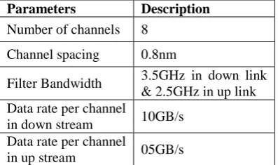
The figure 5 shows the simulation setup of bidirectional DWDM-PON for 8 channels. The different key parameters have been setup as shown in the table 1 below.
Table 1: System Description
Parameters Description
Number of channels 8
Channel spacing 0.8nm
[image:2.595.339.538.657.774.2]Pattern length 29
Modulation format in down stream Varied Modulation format in up stream Varied Bidirectional fiber
length 40km
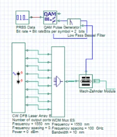
[image:3.595.60.259.55.143.2] [image:3.595.311.510.88.258.2]Optical Transmitter comprises of 8 Channels DWDM transmitters, which is amplified with EDFA at gain 20dB. The eight channel WDM transmitter is shown in figure 6.
Figure 6: 8-channel DWDM transmitter
Here, initially RZ transmitter is used at 5 Gbps data rate then it increases to 10 Gbps using different modulation formats. The channel spacing between the two adjacent wavelengths is 0.8nm whereas data rate per channel are set at 10Gbps and 5Gbps for downstream and upstream respectively. The Optical Line Terminal (OLT) components for single channel are shown in figure 7.
Figure 7: OLT components for single channel
3.RESULTANDDISCUSSION
[image:3.595.100.215.189.299.2]The work in this paper demonstrates high speed DWDM-PON. In WDM-PON, multiplexing of 8 channels which having different wavelengths and each channel is transmitted 40 GB/s data rate. The 8 DWDM channels were separated by 0.8nm at standard International Telecommunication Union (ITU). Table 2 shows the BER values for channel 1 and channel 8 with their respective eye diagram.
Table 2: BER and Eye Diagram of Channel 1 & 8 for Downstream
Channel BER Eye Diagram
1 (1550nm)
3.1662e -14
8(1544.2nm)
1.5700e -10
Similarly, the BER and Eye diagram of channel 1 & 8 for upstream is shown in table 3. In which the data rate is kept at 10Gbps. For simplicity, two channels i.e. first channel at 1578nm and 8th channel at 1581.2nm have been seen to measure the performance of the designed system in downlink direction.
Table 3: BER and Eye Diagram of Channel 1 & 8 for Upstream
Channel BER Eye Diagram
1(1550nm)
1.6632e-020
2(1544.2)
1.8573e-018
It has been observed that BER of the order of e-14 and e-10 has been analyzed for channel one and 8 respectively in downstream direction. Also, BER of the order of 20 and e-18 has been analyzed for reflected wavelength of 1550nm and 1544.2nm respectively and the eye is open in both the cases.
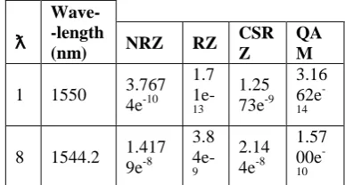
[image:3.595.337.537.385.574.2] [image:3.595.106.226.426.566.2]Table 4: BER for different modulation formats at different wavelengths for (8X10) 80 GB/s at 40km in down link transmission
ƛ
Wave- -length
(nm) NRZ RZ CSR Z
QA M
1 1550 3.767 4e-10 1.7 1e-13 1.25 73e-9 3.16 62e -14
8 1544.2 1.417 9e-8 3.8 4e-9 2.14 4e-8 1.57 00e -10
Similar observations have been carried out for different modulation formats at different wavelengths for 80GB/s at 40km fiber length in upstream transmission. The results are shown in table 5.
Table 5: BER for different modulation formats at different wavelengths for 40GB/s at 40km fiber length in upstream transmission S. No. Wavelengths (nm) Modulation formats
CRZ RZ NRZ
BER BER BER
ƛ1 1578.0
1.6632e-20 3.21e-11 5.7146e-09
ƛ8 1581.2
1.8573e-18 1.e-13
2.4247e-09
For channel 1 obtained values of BER are e-10, e-13, e-9 and e-14 for NRZ, RZ, CSRZ and QAM modulation format at 40km fiber length in down link transmission. Similarly for channel 8 obtained BER values are e-8, e-9, e-8 and e-10 for RZ, NRZ, CSRZ and QAM for same fiber length. Similarly, in upstream for channel 1 BER is e-20, e-11 and e-09 for CRZ, RZ and NRZ formats whereas for channel 8 it is 1e-18, 1.e-13 and 2.4247e-09. It has been observed that QAM modulation format has best format for downstream and CRZ is best for upstream direction.
[image:4.595.324.548.201.346.2] [image:4.595.45.271.308.406.2]Since modulation format QAM produces the satisfactory results for downstream, it is analyzed that at 10Gbps data rate results are better for both the channels, as shown in table 6.
Table 6: BER for QAM modulation format at different data rates in downstream transmission
Lambdas
(ƛ) Data Rate
Modulation Formats
QAM 1
5Gbps 1.7206e-21
8 6.5732e-16
1
10 Gbps 3.1662e-12
8 1.570e-10
Similar observations have been taken for upstream transmission keeping CRZ modulation format and seen the
21 and e-16 for 10GB/s at 60km fiber length. For 40GB/s and for same channels we obtained BER value are e-12 and e-09 at 60km fiber length in down link. Similarly in uplink for channel 1 and channel 2 we obtained BER values are e-20 and e-18 for 5Gbps. For 10GB/s on each channels for same channels we observed BER values are e-11 and e-9 at 40km fiber length for QAM modulation format, so there is tradeoff between BER and data rate. If we increase data rate BER is also increases. The results are shown in table 7.
Table 7: BER at different data rates for CRZ modulation format in uplink transmission
S.
No. Data Rate
Wavelengths (nm) Modulation formats CRZ BER ƛ1 5 Gbps
1550.0 1.6632e-20
ƛ8 1544.2
1.8573e-018
ƛ1
10Gbps
1550.0 3.242e-09
ƛ8 1544.2 2.331e-06 Another aspect of analyzing the system is to vary the total link length in QAM modulation format at 40 Gbps data rate in downstream transmission. The result for the same is shown in table 8.
Table 8: BER at 40Gbps for different total network length
Lambdas (ƛ) Data Rate Total Network Length Modulation Format OQPSK 1 40Gbps 40Km 2.131e-18
8 4.242e-16
1
60 Km 3.324e -12
8 1.000e-9
1
80Km 2.424e-8
8 6.453e-4
At total network length of 60 km the BER value of channel 1 & 8 is e-12and -9 at data rate of 40 Gbps. This result is the optimized result for downstream.
4. CONCLUSION
It has been concluded that for designed 8 Channels DWDM-PON network, the system gives best performance using
QAM modulation format in downlink direction and CRZ modulation format in upstream modulation format. Moreover, 10 Gbps and 5Gbps data rate has been achieved in downstream and upstream directions respectively
[image:4.595.327.536.420.561.2] [image:4.595.31.262.625.732.2][2] E. Harstead, and R. Sharpe “Forecasting of access network bandwidth demands for aggregated subscriber using Monte Carlo methods,” Communication Magazine, IEEE 53.3 (2015): 199-207
[3] Usmani, F., “Efficient dynamic bandwidth allocation schemes in Long Reach Passive Optical Networks-A survey.” High capacity Optical Networks and Emerging/Enabling Technologies (HONET),2014 11th Annual IEEE, 2014 [4] Van der Wee, Marlies, et al. “ Techno- Economic Evaluation
of FTTH Migration for a Network provider : Comparison of NG-AON and TWDM-PON.” Asia Communications and Photonics Conference. Optical society of America,2013 [5] Patrick Iannone,Dora Van Veen, Alan Gnauck and vincent
“Extending capacity in access beyond NG-PON2: WDM Vs TDM.” Optical Communication (ECOC), 2015 European Conference on IEEE,2015
[6] P. Chanclou, C.R.Physique ,” Access network evolution: Optical fiber to the subscriber and impact on the metropolitan and home networks”, Computes Rendus Physique, volume 9, Issues 9-10, November-December 2008
[7] C.Michie, A.E. Kely, J. McGeough, S. Karagiannopopulos, and I. Andonovis,”optically amplified passive optical networks: A power budget analysis,’ Journal of Optical Network, Vol. 8, 2009,pp. 370-382.
[8] J.D.Downie, A.b. Ruffin and J. Hurley,”Ultra low loss optical fiber enabling purely passive 10 Gbits PON system with 100 km length,” opt Express 17, 2009,pp. 2392-2399.
[9] J.Zhang, N, Ansari,” On analyzing the capacity of WDM PONs”, Proc IEEE GlobeCOM, 2009
[10] Y. Lu, Y. Wei, M. Hu, X. Zhou, Z. Qian, Q.Li, Triple functional shared channel in WDM PON by orthogonal modulation and network coding, Opt. Communication 336 (2015)103 – 105.
[11] X.Ma, C. Gan, S. Deng, a novel colorless WDM passive optical network delivering up/downstream signals and video broadcast signal simultaneously, opt. switch. Netw.(2013) 100-105.
[12] H. Rohde, S. Smolorz, J.S. Wey, E. Gottwald, coherent optical access networks, OFC 2011, paper OTuB1.
[13] K.Kikuchi, S. Tsukamoto, Evaluation of sensitivity of the digital coherent receiver, J. Lightwave Technol.26 (2008) 1817-1822.