3093
Microstructural Evolution and Machining Behaviour of
in-situ Aluminium Matrix Composites fabricated by
Stir Casting Process
Arjun Kumar
1, Arun Kumar Chaudhary
2Research scholar1, Assistant Professor2, Industrial & Production Engineering Department 1,2, College of Technology, G.B Pant University of Agriculture & Technology, Pantnagar,Uttarakhand1,2
Email: [email protected]1,[email protected]2
Abstract- In the present work we brought a polymer precursor into liquid aluminum and afterward in-situ pyrolyzed to deliver castings of metal matrix composites (P-MMCs) containing silicon-carbonitride (SiCNO) ceramic particles. An aluminum alloy which has low elasticity and hardness is being composited with other materials to enhance its properties and decrease its drawback. Aluminum based metal matrix composite are casted utilizing aluminum alloy fortified with different volume division of hexamethyl disilazane (HMDS) which produce ceramic phases. A stir casting process has been utilized under an idle air to produce aluminum matrix composite. Further the synthesized aluminium based metal matrix composites are machined by EDM. Metal removal Rate and surface roughness of the composites are estimated and their variations in performance are studies using orthogonal array.
Keywords-Metal matrix composites (MMCs), Polymer derived ceramics, Microstuctural evaluation, Machining.
1. INTRODUCTION
The wide range of availability of aluminium has made it an important material for manufacturing many components. Aluminum is the third most plentiful material available in nature. It has supplanted the ferrous element in extensive variety of utilizations because of its particular properties like low density, corrosion resistance because of passivation, light in weight and so forth. Aluminum additionally has defective properties which keep it from being connected in different fields. Keeping in mind the end goal to beat the imperfections of pure aluminum alloys, another material called aluminum composite was discovered. Aluminum composites are likewise called as aluminum metal matrix composites. A metal matrix composite is a blend of two unmistakable metals to acquire an intensified material known as reinforced material. Solidification process is the most prudent, practical and flexible procedure to create MMCs for extensive scale in manufacturing sectors. Pradepet al. [1] looked into the vital solidification principles fundamental the microstructure evaluation which administers the composite properties. Surappa [2] investigated particle-solidification front collaborations in various MMCs, and inferred that characteristic material properties and additionally processing variables play a major role in controlling the microstructural evaluation in the last MMCs. A large portion of the specialized difficulties in solidification processing can be extraordinarily limited by receiving in-situ composite approach by which
ceramic particles are created within the molten state by means of chemical reaction between the added precursor and the host metal. In-situ composites offer predominant microstructural/mechanical characteristics when contrasted with their conventional partners. For example, in-situ MMCs included uniform dispersion of fine-sized thermodynamically stable ceramic particles, clean and unoxidized ceramic metal interfaces alongside high interfacial strength, enhanced hardness/yield strength and elastic modulus (Tjong et al. [3]).
2. EXPERIMENTAL PROCEDURE
2.1. Matrix materials and polymer precursor
An Al6061 Wrought aluminum alloy (commercial purity 99.5%) is chosen as the matrix materials. Alloy of this series have flexible heat treatable expelled alloy with medium to high strength capabilities. Hexamethyl Disilazane (HMDS) was used as a precursor for reinforcement. The weight division of polymer precursor to be included into liquid Al/Al-alloy can be assessed by the following formula [4].
=
(1)
3094
2.2.Material characterization
Optical microscope (Leica DM2700, Germany), scanning electron microscope (JEOL JSM-6610LV, Japan) coupled with energy dispersive spectroscopy (EDS) and transmission electron microscope (Tecnai T20, FEI Company) were utilized for micro structural studies. Diffraction spectra of the as-cast composites were collected using an X-Ray Diffractometer (PANalyticalX'pert-Pro (MPD), Netherlands) [10,11].In the present work; composites are fabricated using matrix material Al6061 and reinforcement material Hexamethyl Disilazane (HMDS). The alloy composition and mechanical properties of Al6061 is tabulated. Three different compositions, taking 10%, 20% and 30% disilazne as a constant required composites are fabricated. The Table-1 shows the composition in which the material is fabricated. The fabrication of composites is done by stir casting method, Due to its suitability in producing uniformly distributed reinforcements. Al6061 was purchased in the form of ducts and then were cut into pieces to as per requirement of the crucible. Table-2 and 3 shows the composition of Al6061 alloy and its mechanical properties respectively. Casting process is done by stir casting technique and the machining process is done by EDM Machine. The Surface roughness of the machined surface is tested in Surface roughness testing equipment. The parametric studies were conducted for the surface roughness and material removal rate.
Table 1. Compositions of Al6061-Disilazne
COMPOSITION Al1060
(in gram)
DISILAZANE (in gram)
1 700 70
2 700 140
[image:2.595.123.480.92.307.2]3 700 210
Table 2. Chemical Compositions in percent by weight of Al6061
Alloy 6061
Si 0.4-0.8
Fe 0.7
Cu 0.15-0.40
Mn 0.15
Mg 0.08-1.2
Zn 0.25
Ti 0.15
Cr 0.04-0.35
Al min 99.50
Table 3. Mechanical properties of Al6061 Density (g/cm3) 2.7 Ultimate Tensile Strength (MPa) 310 Yield Tensile Strength(MPa) 276
Elongation % 12
Modulus of Elasticity 68.9 Poisson ratio 0.33
Metallic moulds of required shapes are used to obtain the specimens for tests. The molten metal of aluminium obtained by stir casting is poured into the moulds.
[image:2.595.299.532.445.673.2]
3095
2.3. Fabrication of Al6061/SiC Composites -
Stir casting
Stir casting includes filtration of particles or fiber packages by liquid metals or alloys. At first, the solid reinforced materials are mixed in the metallic matrix melt, and the mixture is then permitted to harden in a particular shape or ingot [5].This is achieved by utilizing conventional processing machineries on a continuous or semi continuous background having great molecule wettability. The homogeneity of the MMCs relies upon the mixing speed and time. For Al– SiC-based MMCs; it has been discovered that the expanding of stirring speed prompts get more homogeneous MMC along the deposition direction. Good wetting in the molten metal also depends on the degree of mixing that can be controlled by different shapes of mixer blade [6]. The schematic of stir casting is depicted in Fig.2 above.
3. EXPERIMENTAL ILLUSTRATIONS
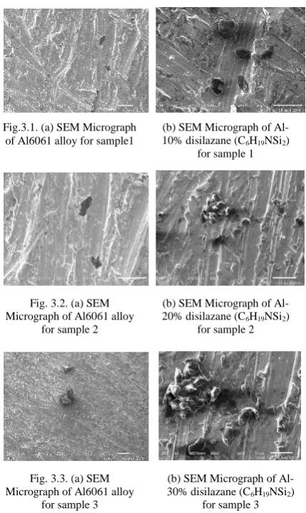
3.1. Microstructure
Scanning Electron Microscopy (SEM) is the device used to view the particles and grain size of the specimen. The specimen is prepared by polishing 10×10×10 mm cube. 5% of volume of HF etchant is used to etch the surface of the sample and it is washed in distilled water before carrying out SEM. The micrographs obtained by scanning electron microscopy show the dispersion of the reinforcement particles in the matrix [12,13,14]. The SiC particles were evenly distributed was clogged at some places. There is an agglomeration of particles. Appearances of small pits are due to oxidation of surface by the
etchants or may be by the grinding of the surface. Thread like grain boundaries are due to fine particles of reinforcements added with matrix.
3.2.X-Ray diffraction
[image:3.595.166.438.83.269.2]The X-ray spectra from the casted specimen are shown in Figure 4, which shows the formation of the Al2Si Fig. 2. Schematic diagram of Stir casting of MMC.
Fig.3.1. (a) SEM Micrograph of Al6061 alloy for sample1
(b) SEM Micrograph of Al-10% disilazane (C6H19NSi2)
for sample 1
Fig. 3.2. (a) SEM Micrograph of Al6061 alloy
for sample 2
(b) SEM Micrograph of Al-20% disilazane (C6H19NSi2)
for sample 2
Fig. 3.3. (a) SEM Micrograph of Al6061 alloy
for sample 3
(b) SEM Micrograph of Al-30% disilazane (C6H19NSi2)
[image:3.595.311.526.338.698.2]3096 intermetallic phase. The formation of silicides when
[image:4.595.73.294.335.466.2]metals are reacted with polymer-derived silicon carbonitride has been reported in the literature. [7, 8]. The nature of their experiments was quite different from ours, because in our case, a small amount of the polysilazane was added to the metal melt and pyrolysis was carried out within the molten melt. Janakiraman et al.[8] used mixed polysilazane and heated them from 10000C to 16000C in argon atmosphere. It should be kept in mind that the peaks of SiCNO phases have not appeared in diffraction spectra as they are amorphous in nature. It is more obvious that while Al peaks are observed in all fabricated composites[15]. It is pertinent to mention that the mean volume fraction of PDC particles in in-situ MMCs having Al2Si crystals is found to be always greater than that of projected volume fraction, which was about 2.5%.
Fig. 4. XRD spectra of fabricated in-situ MMC
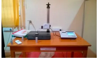
4. SURFACE ROUGHNESS TEST
[image:4.595.79.276.607.724.2]Surface Roughness (Ra) is a component of surface texture. It is quantified by the deviations in the direction of the normal vector of a real surface from its ideal form. If these deviations are large, the surface is rough; if they are small, the surface is smooth. The Ra is measured using SURFTEST machine shown in Figure 5.
Fig. 5. Schematic diagram of Surface Roughness testing machine.
Ra is typically considered to be the high-frequency, short-wavelength component of a measured surface (see surface metrology). However, in practice it is often necessary to know both the amplitude and frequency to ensure that a surface is fit for a purpose. Ra of the samples is measured by using surface testing machine and the values are tabulated in Table 4.
Table4. Experimental values of Roughness Testing
4.1.L9 Orthogonal array
While there are numerous standard orthogonal arrays accessible, each of the exhibits is intended for a particular number of design variable and levels. For instance, in the event that one needs to lead an investigation to comprehend the impact of 4 different independent variables with every variable having 3 set values (level values), at that point a L9 orthogonal array may be the correct decision. The L9 symmetrical array is intended for understanding the effect of 4 independent factors each having 3 factor level values. This exhibit expects that there is no association between any two factors. While much of the time, no cooperation model presumption is substantial, there are a few situations where there is an unmistakable confirmation of interaction. A run of the mill instance of interaction would be the interaction between the material properties and temperature. At that point readings are classified in below Table 5.
The Material Removal Rate (MRR) can be characterized as the mass of material removal partitioned by the machining time. Another approach to characterize MRR is to imagine an instantaneous material removal rate as the rate at which the cross segment zone of material being removed travels through the work piece. The MRR values are calculated and displayed in Table 5.
Table 5. Metal Removal Rate and Surface Roughness values
S.NO. IP TON V MRR(mg/min) SR
(µm)
1 5 10 10 50 3.472
2 5 15 20 59.5 4.213
3 5 20 50 65 6.432
4 7.5 10 30 43.33 3.124
Exp. No
IP (A)
Ton (µs)
Gap Voltag
e (volt)
Rough ness Value
(Ra) µm
Time duration
during experime
nt (min)
1 5 10 20 3.472 3
2 7.5 15 30 6.432 2
3 10 20 50 6.047 2
3097 5 7.5 15 50 85 6.047
6 7.5 20 20 56 3.214
7 10 10 50 48 2.912
8 10 15 20 64 4.543
9 10 20 30 58.5 4.012
5. CONCLUSION
(1)In-situ aluminium matrix composites were fabricated successfully by injecting cross-linked polysilazane directly into, and having it convert to the SiCNO ceramic phase, within molten Al/Al-alloy using liquid stir- casting method.
(2)During in-situ pyrolysis, it is possible to minimize the formation of Al2Si phase by reducing the processing temperature from 800°C to 700°C. (3)Machining Aluminium metal matrix composites
in the EDM machine produces good performance measure values.
(4)The variation of surface roughness with respect to the gap voltage is very significant. The percentage of reinforcement decreases the surface roughness in aluminium composites.
Acknowledgments
The authors acknowledge Head IPED and Dean, College of Technology, G.B. Pant University of Agriculture & Technology, Pantnagar, Uttarakhand and Technical Education Quality Improvement Programme (TEQIP)-III of All India Council for Technical Education (AICTE), New Delhi, India for providing financial assistance for doing this research
work. (A.1)
REFERENCES
[1] P. Rohatgi, and R. Asthana.“The solidification science in MMCs: the influence ofMerton Flemings”.The Journal of the Minerals, Metals & Materials Society, 53:9–13, 2001.
[2] M. K. Surappa.“Microstructural evolution during solidification of DRMMCs(Discontinuous reinforced metal matrix composites): state of art”.Journal of Materials Processing Technology, 63:325–333, 1997.
[3] S.C. Tjong, and Z.Y. Ma.“Microstructural and mechanical characteristics of in-situ metal matrix composites”.Materials Science and Engineering: R: Reports, 29:49–113, 2000.
[4] N. M. Chelliah, H. Singh, R. Raj, and M.K. Surappa.“Processing, microstructural evolution and strength properties of in-situ magnesium matrix composites containing nano-sized polymer
derived SiCNO particles”.Materials Science and Engineering: A, 685:429–438, 2017.
[5] J. Hashim, L. Looney, and M. S. J. Hashmi. “Metal matrix composites: production by the stir casting method”.Journal of Materials Processing Technology, 92–93:1–7, 1999.
[6] A. R. A. McLelland, H. V. Atkinson and P. R. G. Anderson.“Thixoforming of a novel layered metal matrix composite”.Materials Science and Technology, 15:939–945, 1999.
[7] H. Y. Ryuand R. Raj. “Selection of tin as the Interconnect Material for Measuring the Electrical Conductivity of Polymer‐Derived sicn at High Temperatures”. Journal of the American Ceramic Society, 90(1):295–97, 2007.
[8] N. Janakiraman, T. Höche, J. Grins, and S.Esmaeilzadeh. “Synthesis and phase evolution of Mg–Si–C–N ceramics prepared by pyrolysis of magnesium-filled poly (ureamethylvinyl) silazane precursor”.Journal of Materials Chemistry, 16:3844–3853, 2006.
[9] Z. Chun-Yan, Z. Rong-Chang, L. Cheng-Long, and G. Jia-Cheng.“Comparison of calcium phosphate coatings on Mg-Al and Mg-Ca alloys and their corrosion behavior in Hank’s solution”. Surface and Coatings Technology, 204(21–22): 3636–3640, 2010.
[10]X. Du, T. Gao, G. Liu, andX. Liu. “In situ synthesizing SiC particles and its strengthening effect on an Al–Si–Cu–Ni–Mg piston alloy”. Journal of Alloys and Compounds, 695:1–8, 2017.
[11]J. Hirsch, and T. Al-Samman. “Superior light metals by texture engineering: Optimized aluminum and magnesium alloys for automotive applications”. ActaMaterialia, 61(3):818–843, 2013.
[12]M. B. Kannan, and R. K. S. Raman. “In vitro degradation and mechanical integrity of calcium-containing magnesium alloys in modified-simulated body fluid”. Biomaterials, 29:2306– 2314, 2008.
[13]Z. Li, X. Gu,S. Lou, andY. Zheng. “The development of binary Mg-Ca alloys for use as biodegradable materials within bone”. Biomaterials, 29(10):1329–1344, 2008.
[14]M. Rashad, F. Pan, A. Tang, M. Asif, S. Hussain, J. Gou, andJ. Mao. “Improved strength and ductility of magnesium with addition of aluminum and grapheme nanoplatelets (Al+GNPs) using semi powder metallurgy method”. Journal of Industrial and Engineering Chemistry, 23:243–250, 2015.
![Fig. 1. Components of, casting furnace used in processing of in-situ MMCs.[4]](https://thumb-us.123doks.com/thumbv2/123dok_us/736910.1083552/2.595.123.480.92.307/fig-components-casting-furnace-used-processing-situ-mmcs.webp)