Progress In Electromagnetics Research M, Vol. 65, 151–164, 2018
Digital Harmonic Canceling Algorithm for Power Amplifiers Based
on Nonlinear Adaptive Filter
Xuan Peng1, 2, *, Xin Qiu1, 2, and Fuqi Mu1, 2
Abstract—High power amplifier not only causes in-band intermodulation but also causes out-of-band harmonic distortion. For a wideband transmitter, harmonic distortion out of communication frequency can be restrained by a radio-frequency filter, but harmonic distortion in the communication frequency is difficult restrain. In this paper, we develop harmonic memory polynomial to model harmonic distortion and then propose a digital harmonic canceling algorithm based on direct learning structure — nonlinear filtered-x affine projection algorithm (NFX-APA). Simulation and measurement results demonstrate that this novel digital canceling method can cancel harmonic effectively.
1. INTRODUCTION
Nowadays wideband transmitters need to support multi-communication-channels at different frequency bands, such as Wi-Fi, LTE Advanced, and 5G. Sometimes cognitive radio systems and software defined radios (SDRs) transmitter should work from tens of megahertz to several gigahertz, and designing such a wideband transmitter needs significant effort.
In order to increase the efficiency of high power amplifiers (HPA) and signal to noise ratio of the receiver, we often drive HPAs into a nonlinear region. However, nonlinear behavior of HPAs always gives rise to in-band intermodulation and out-of-band harmonic distortion, which causes spectrum electromagnetic pollution. In-band intermodulation can be effectively compensated by digital predistortion (DPD) technique with a direct learning structure [1, 2] or indirect learning structure [3, 4], and this technique is well explored in the literature. When dealing with harmonic distortion, a radio-frequency filter can be utilized to filter harmonic distortion out of communication band, but there exist difficulties in filtering harmonic distortion in the communication band. It may use different communication links of different communication bands to avoid harmonic distortion falling on the same communication band, which significantly increases the cost and volume of transceiver when communication frequency range is of different orders. The demand for decreasing cost and volume requires sharing a single HPA and radio-frequency filter among multiple communication bands, thus it is desirable to exploit more effective techniques.
One way to reduce harmonic distortion is using RF (radio frequency) bandpass filters with tunable center frequency and bandwidth [5, 6]. In the past several years, considerable attention has been paid to tunable RF filters. However, limits of the range of center frequency and bandwidth are not enough for practical application of a wider frequency band. Another way to suppress harmonic distortion is using couplers or combiner [7–9]. However, all these circuits cannot cancel harmonic distortions in the communication band. Analog method to suppress harmonic distortion remains an ongoing challenge.
Traditional DPD techniques cannot be used to cancel harmonic distortion [1–4, 10–15] because all these techniques are based on memory polynomials [1, 16], generalized memory polynomials [4] or
Received 9 January 2018, Accepted 10 February 2018, Scheduled 9 March 2018 * Corresponding author: Xuan Peng ([email protected]).
Volterra series [3, 15], etc. DPD techniques including harmonic distortions need impractical sampling rate requirements for the DAC (Digital to Analog Converter) and ADC (Analog to Digital Converter). Some techniques are developed for reducing DPD sampling rate, but they are not applicable to this problem. Bassam et al. [10] proposed a 2-D DPD architecture applicable to linearization of concurrent dual-band transmitters based on memory polynomials and indirect learning structure, which is not suitable for the harmonic distortions. Liu et al. [12] proposed a DPD technique in order to reduce in-band feedback bandwidth, and this technique only considers in-band intermodulation. On the other hand, Piazza et al. [14] gave a method for multicarrier transmission based on memory polynomials and direct learning structure, which is also not suitable for harmonic distortions. Although digital predistorters cannot deal with harmonic distortions yet, compared with analog way, digital processing techniques often provide several advantages such as accuracy and lower cost, thus novel digital processing methods have to be in place.
In this paper, we will present a new harmonic canceling predistorter which can work effectively on each harmonic and combine with digital predistorters to compensate the nonlinear behavior of HPAs. We firstly introduce an improved memory polynomial to model harmonic distortions which are also down-converted to baseband as complex signals. After modeling the harmonic distortions, we calculate predistorters coefficients using a nonlinear adaptive filter based on the nonlinear filtered-x adaptive algorithm and the direct learning structure.
This paper is organized as follows. Section 2 mainly describes a wideband transmitter system and develops a harmonic memory polynomial in it. With the introduction of harmonic memory polynomial, Section 3 develops the Nonlinear Filtered-x Affine Projection Algorithm (NFX-APA) extended from NFX-LMS (Nonlinear Filtered-x Least Mean Square) and NFX-RLS (Nonlinear Filtered-x Recursive Least Square) algorithm. Simulation and measurement results given in Section 4 demonstrate the effectiveness of our digital harmonic canceling techniques in the wideband transmitter. Finally, we state the conclusion of the proposed method in Section 5.
2. HARMONIC CANCELING SYSTEM
2.1. Distortions and Nonlinearity of the Transmitter System
The nonlinear behavior of a wideband transmitter mainly comes from HPAs, which has been studied by researchers for years, especially for in-band modulation distortion and cross modulation distortion [1, 10, 14, 16], but harmonic distortion has received less attention.
The nonlinear behavior of HPA produces in-band intermodulation and out of band harmonic distortions. In-band intermodulation results in well-known bandwidth regrowth of the signal spectrum at the output of HPAs. On the other hand, out of band modulation results in harmonic distortions at the output of HPAs, which causes spectrum pollution. For a multi-band signal, the nonlinear behavior also produces cross-modulation. These effects are shown in Fig. 1.
The in-band intermodulation has been studied for many years, which can be modeled by Volterra series, Hammerstein system, Wiener system, memory polynomial, generalized memory polynomial, orthogonal base functions, etc. Among them, memory polynomial is the most popular simplified Volterra series, because of its tradeoff between complexity and performance. The memory polynomial model including memory effect and even order nonlinearity is given by,
y1(n) =
D
d=0
N
i=1
h11(d, i)x1(n−d)|x1(n−d)|i−1 (1)
where x1(n−d) is the sample of HPA input modulated baseband signal that is d-delayed, y1(n) the sample of the output baseband signal, h11(d, i) the polynomial coefficient that depicts HPA nonlinear channel,Dthe memory depth, andN the nonlinearity order. x1(n−d),y1(n) andh11(d, i) are complex values because they are the lowpass equivalence of bandpass signals and system.
Progress In Electromagnetics Research M, Vol. 65, 2018 153
Figure 1. Power spectrum of signal before and after HPA.
because of low cost and small volume [5, 6, 17]. In [17], an ultra-wideband efficient linearized power amplifier proposed supports 0.4 to 4.2 GHz bandwidth, whose communication frequency range is of different orders. A single fixed RF filter cannot be used in this case because there may be another transmitting signal at the harmonic frequency. In order to share a single HPA and a single radio-frequency filter, harmonic distortion in the communication band should be suppressed in a different way to satisfy power spectrum mask. Harmonic distortion poses an important challenge to wideband transmitter design.
Because the harmonic distortion is far away from the signal, conventional DPD techniques have difficulties to deal with it. The limitation of the analog approach makes suppression of harmonic difficult.
2.2. Harmonic Distortion Analysis
Accurate modeling of the harmonic distortion is needed before suppressing harmonic distortion. The conventional baseband modeling approach like memory polynomial needs to be derived differently in this case. Considering bandpass signal in the Volterra channel [18], we can express HPA output bandpass signal with the HPA input bandpass signal as
y(n) = +∞
q1=0
hq1x(n−q1) + +∞
q1=0 +∞
q2=0
hq1q2x(n−q1)x(n−q2) +. . .
+ +∞
q1=0 +∞
q2=0
. . .
+∞
qm=0
hq1... qmx(n−q1)x(n−q2) . . . x(n−qm) +. . . (2)
The HPA input bandpass signal at carrier frequency ω can be defined as a lowpass equivalent complex signal given by,
x(n) = Rex1(n)ejωn
= 1
2
x1(n)ejωn+x∗1(n)e−jωn
(3)
Using Equation (3), the quadratic term and cubic term in Equation (2) can be developed as follows, which assumes a same delayed timeq1=q2 =q3 to decrease the complexity of polynomials:
+∞
q1=0 +∞
q2=0
hq1q2x(n−q1)x(n−q2)
= 1
22 +∞
q1=0
hq1
x1(n−q1)ejω(n−q1)+x∗1(n−q1)e−jω(n−q1)
= 1 22
+∞
q1=0
hq1
x21(n−q1)e2jω(n−q1)+|x1(n−q1)|2+x21∗(n−q1)e−2jω(n−q1)
(4)
+∞
q1=0 +∞
q2=0 +∞
q3=0
hq1q2q3x(n−q1)x(n−q2)x(n−q3)
= 1
23 +∞
q1=0
hq1
x1(n−q1)ejω(n−q1)+x∗1(n−q1)e−jω(n−q1)
3
= 1
23 +∞
q1=0
hq1
x31(n−q1)e3jω(n−q1)+ 3x1(n−q1)|x1(n−q1)|2ejω(n−q1)
+3x∗1(n−q1)|x1(n−q1)|2e−jω(n−q1)+x31∗(n−q1)e−3jω(n−q1)
(5)
where x1(n − q1)|x1(n−q1)|2ejω(n−q1) and x∗1(n − q1)|x1(n−q1)|2e−jω(n−q1) are the HPA output intermodulation distortion at the transmitter signal frequency; x21(n − q1)e2jω(n−q1) and x21(n −
q1)e2jω(n−q1) are the second harmonic distortion at the output of the HPA; x31(n−q1)e3jω(n−q1) and
x31∗(n−q1)e−3jω(n−q1) are the third harmonic distortion of transmitter signal.
Although in-band intermodulation derivation only includes odd order nonlinear terms of straight mathematical manipulations, it is proven in the test that the even order nonlinear terms are also effective in the baseband channel modeling [19]. Hence we defineiorder harmonic memory polynomial extended from Equations (4) and (5) as follows:
yi(n) = D
d=0
N1
j=i
h1i(d, j)xi1(n−d)|x1(n−d)|j−i (6)
whereh1i(d, j) is the parameters of harmonic memory polynomial produced by the transmitting signal
x1.
2.3. Harmonic Canceling System
After modeling harmonic distortion with harmonic memory polynomial of Eq. (6), we can improve conventional DPD techniques to suppress harmonic distortion. There are two types DPD technique, indirect learning architecture (ILA) and direct learning architecture (DLA). ILA directly calculates HPA post-inverse function as the predistorter instead of calculating pre-inverse function [3, 4, 10, 16], assuming that HPA nonlinear behavior is invertible. DLA firstly estimates nonlinear function of the HPA and then calculates the predisorter parameters by analysis method [1, 11] or adaptive filter [2, 12– 14]. Indirect learning architecture has less computational complexity than direct learning architecture, but indirect learning is sensitive to measured noise, thus direct learning has better performance than indirect learning [20]. Moreover, DLA has a more flexible structure so that it can be improved to decrease feedback bandwidth [12]. The harmonic distortion has a smaller power than transmitting signal, which results in a low signal-noise ratio for parameter estimation. Furthermore, it is difficult to demonstrate the invertible property of the harmonic distortion function. Hence, the new harmonic canceling method we proposed here is built on direct learning architecture.
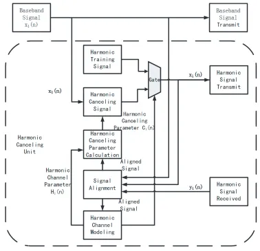
Figure 2 illustrates the basic structure of the harmonic canceling system, which is similar to DPD structure except that predistorter and feedback path work at the harmonic frequency. This structure can be combined with DPD structure to simplify the whole structure and decrease computational resources. To simplify the discussion, this figure only cancels one harmonic distortion.
The digital harmonic canceling system sends transmitting signalx1(n) at carrier frequency f0 and
Progress In Electromagnetics Research M, Vol. 65, 2018 155
Figure 2. Digital harmonic canceling system.
Figure 3. Power spectrum of two signal before and after HPA.
modulation products between x1(n) and xi(n), intermodulation ofxi(n) at harmonic frequencyif0, as Fig. 3 illustrated.
These signals after HPA at the harmonic frequency if0 pass the attenuator and feedback path, which will be received by signal processor. The iorder harmonic received signal yi(n) includes xi(n), harmonic distortion ofx1(n), cross modulation products betweenx1(n) andxi(n), and intermodulation ofxi(n). Because the power ofxi(n) is small, its nonlinear intermodulation terms can be ignored. Thus, recalling Equation (6), yi(n) can be modeled as follows,
yi(n) = D
d=0
N1
j=i
h1i(d, j)xi1(n−d)|x1(n−d)|j−i+
D
d=0
Ni
j=0
hii(d, j)xi(n−d)|x1(n−d)|j (7)
(Whenj = 0). The nonlinearityNi is smaller thanN1, because the power ofxi(n) is smaller thanx1(n) so that the cross-modulation terms are smaller than harmonic terms in the same nonlinearity order. In order to simplify representation, Equation (7) can be developed with vector and matrix form as follows:
yi(n) = x1i(n)h1i+xii(n)hii (8)
Yi(n) = X1i(n)h1i+Xii(n)hii= [ X1i(n) Xii(n) ]∗[ h1i hii ]T =Xi(n)hi (9) where
h1i = [h1i(0,1), h1i(1,1), . . . , h1i(D, N1)]T
hii = [hii(0,1), hii(1,1), . . . , hii(D, Ni)]T
x1i(n) = xi1(n), . . . , x1i(n−d), xi1(n)|x1(n)|, . . . , xi1(n−d)|x1(n−d)|N1−i
xii(n) = xi(n), . . . , xi(n−d), xi(n−1)|x1(n−1)|, . . . , xi(n−d)|x1(n−d)|Ni
Yi(n) = [yi(n), yi(n−1), . . . , yi(n−L+ 1)]T
X1i(n) = ⎡ ⎢ ⎣
x1i(n)
x1i(n−1)
. . . x1i(n−L+ 1)
⎤ ⎥
⎦ Xii(n) = ⎡ ⎢ ⎣
xii(n)
xii(n−1)
. . . xii(n−L+ 1)
⎤ ⎥ ⎦
3. NONLINEAR FILTERED-X AFFINE PROJECTION ALGORITHM
In this section, we will discuss the Nonlinear Filtered-x Affine Projection Algorithm (NFX-APA) of the harmonic canceling system for one harmonic distortion, which can be shown as Fig. 4.
The baseband signal unit sends baseband signalx1(n) at carrier frequencyf0, while the harmonic channel modeling unit firstly controls the gate to select the output of the harmonic training signal unit as thei order harmonic signalxi(n) at frequency if0. The output of the harmonic training signal unit is thei order harmonic training signal that is uncorrelated with x1(n). The power ofxi(n) is close to the power of i order harmonic distortion of x1(n) so that it has little effect on the HPA. The signal alignment unit aligns transmitting signal x1(n) and xi(n) with received signal yi(n) according to the correlation between the transmitting and received signals. After that, the harmonic channel modeling unit combines x1(n) and xi(n) with i order harmonic received signal yi(n) to model the nonlinear channel of HPA at theiorder harmonic frequency. The irrelevance betweenx1(n) and xi(n) guarantees the accuracy of modeling HPA harmonic channel. The channel estimation can use LS (Least Square) estimation or adaptive method such as LMS (Least Mean Square) or RLS (Recursive Least Square) algorithm. When using LS estimation and Equation (9), the nonlinear channel parameter hi can be derived as follows,
hi=XHi Xi−1XHi Yi (10)
When theiorder harmonic HPA channel is modeled, the harmonic channel modeling unit controls the gate to select the output of the harmonic canceling signal unit as the i order harmonic signal
xi(n). Meanwhile, the harmonic channel modeling unit sends nonlinear channel parameter hi to the harmonic canceling parameter calculation unit. The harmonic canceling parameter calculation unit uses an adaptive filter NFX-APA to calculate harmonic canceling parameter and then sends it to the harmonic canceling signal unit. After some iterations, the iorder harmonic distortion is suppressed by
xi(n).
The harmonic canceling signal can be generated from the baseband transmitting signalxi(n) with the harmonic memory polynomial of Eq. (6),
xi(n) = D
d=0
N1
j=i
Ci(n, d, j)xi1(n−d)|x1(n−d)|j−i=x1i(n)Ci(n) (11)
Progress In Electromagnetics Research M, Vol. 65, 2018 157
Figure 4. Harmonic canceling system based on NFX-APA algorithm.
parameter identification problem. The harmonic distortion can be viewed as noise, which is correlated with signalx1(n). x1(n) generates xi(n) and passes a nonlinear system to cancel harmonic distortion. This problem is a nonlinear prefilter problem [21] like DPD, thus NFX-LMS, NFX-RLS can be applied to this problem. However, here we introduce nonlinear filtered-x affine projection algorithm extended from the affine projection algorithm, which converges more quickly than RLS and LMS in same iterative times. The affine projection adaptive filter is developed from NLMS (Normalized Least Mean Square). In order to decrease the power of harmonic distortion at the harmonic frequencies, here errorei(n) can be defined as theiorder harmonic received signalyi(n) and measured noisevi(n) from Equation (7),
ei(n) = yi(n) +vi(n) = D
d=0
N1
j=i
h1i(d, j)xi1(n−d)|x1(n−d)|j−i
+ D
d=0
Ni
j=0
hii(d, j)xi(n−d)|x1(n−d)|j+vi(n) (12)
Using Equation (8), the harmonic distortionRi(n) after HPA produced by the transmitting signal
x1(n) and the harmonic canceling terms Zi(n) after HPA produced by the i order harmonic canceling signalxi(n) can be expressed separately as follows,
Ri(n) = D
d=0
N1
j=i
Zi(n) = D d=0 Ni j=0
h1i(d, j)xi(n−d)|x1(n−d)|j =xii(n)hii(n) (14)
According to Eqs. (13) and (14), we have,
ei(n) =Ri(n) +Zi(n) +vi(n) (15)
Equation (15) can be extended in matrix form similar to Eq. (9),
ei(n) =Ri(n) +Zi(n) +vi(n) (16) whereZi(n) is used to compensateRi(n) caused by the nonlinearity of HPA. Aiming at minimizing the squared Euclidean norm of the change of harmonic cancel parameter Ci(n), with the constraint that whenCi(n+ 1) is applied the error defined as ei(n) becomes zero, using the Lagrange multipliers, cost function can be derived as follows,
J(n) =Ci(n+ 1)−Ci(n)2+ Re eHi (n)λ
(17)
The derivative of the cost function with respect toCi(n+ 1) is
∂J(n)
∂Ci(n+ 1) = 2(Ci(n+ 1)−Ci(n)) +
∂eHi (n)
∂Ci(n+ 1)λ (18) where∂ei(n)/∂Ci(n) can be developed as Equation (19),
∂ei(n)
∂Ci(n+ 1) =
∂ei(n)
∂Ci(n+ 1), . . . ,
∂ei(n−L+ 1)
∂Ci(n+ 1)
∂ei(n)
∂Ci(n+ 1) =
∂Ri(n)
∂Ci(n+ 1)+
∂Zi(n)
∂Ci(n+ 1)+
∂vi(n)
∂Ci(n+ 1)
= 0 +
∂ D d=0 Ni j=0
h1i(d, j)xi(n−d)|x1(n−d)|j
∂Ci(n+ 1) + 0
= D d=0 Ni j=0
∂h1i(d, j)xi(n−d)|
x1(n−d)|j
∂Ci(n+ 1)
= D
d=0
∂xi(n−d)
∂Ci(n+ 1) Ni
j=0
h1i(d, j)|x1(n−d)|j
(19)
Using Equation (11),∂xi(n−d)/∂Ci(n+ 1) can be derived as follows, assuming thatCi(n+ 1)≈
Ci(n),
∂xi(n−d)
∂Ci(n + 1) =
∂
D+d
d=d N1
j=i
Ci(n+ 1, d, j)xi1(n−d)x1(n−d)j−i
∂Ci(n+ 1)
= ∂C
H
i (n + 1)X1i(n−d)
∂Ci(n + 1) =X1i(n) (20)
And we defineg(r, n) as follows,
g(d, n) = Ni
j=0
Progress In Electromagnetics Research M, Vol. 65, 2018 159
Using Eqs. (20) and (21), we obtain
u(n) = ∂ei(n)
∂Ci(n+ 1) = D
d=0
X1i(n−d)g(d, n)
A(n) = ∂ei(n)
∂Ci(n+ 1) = [u(n), . . . , u(n−L+ 1)]
(22)
Setting the derivative Equation (18) to zero, we get
δCi(n+ 1) =Ci(n+ 1)−Ci(n) =−1 2
∂eHi (n)
∂Ci(n+ 1)λ=− 1 2A
H(n)λ (23)
Assuming that ei(n)|C
i(n+1) ≈ ei(n) +δCi(n+ 1)A(n) and using the constraint ei(n)|Ci(n+1) =
Ri(n) +Zi(n)|Ci(n+1) = 0, we obtain,
ei(n) +δCi(n+ 1)A(n) = 0 (24)
Thus, using Eq. (23) in Eq. (24),
ei(n)− 1 2A
H(n)A(n)λ= 0 (25)
Solving Equation (25) for the Lagrange vectorλ, we arrive at the following formulation,
λ= 2 ei(n)
AH(n)A(n) (26)
Substituting this solution into Equation (23) yields the change of Ci(n),
δCi(n+ 1) =−AH(n)AH(n)A(n)−1ei(n) (27) To control the change ofCi(n) from one adaptation cycle to the next, step-sizeμis introduced into Equation (27), yielding
Ci(n+ 1) =Ci(n)−μAH(n)AH(n)A(n)−1ei(n) (28) To avoid singularity of matrix inversion, Equation (28) is developed as Equation (29), andεin this equation is properly small.
Ci(n+ 1) =Ci(n)−μAH(n)A(n)AH(n) +εI−1ei(n) (29) Due to the methodology we used, the measured noise v(n) and stability should be taken into account. Here we define the harmonic canceling parameter error vector εi between ideal harmonic canceling parameterCi and harmonic canceling parameter Ci(n) as follows,
εi(n) =Ci−Ci(n) (30)
Using this definition in the harmonic canceling parameter updated Equation (29), rearranging and simplifying terms, we have,
E εi(n+1)2− εi(n)2
= μ2E eiH(n)A(n)AH(n)−1ei(n)
+2μE Re
ζiH(n)A(n)AH(n)−1ei(n)
(31)
where
ζi(n) =A(n) (Ci−Ci(n))
In order to decrease the mean square of the harmonic canceling parameter error vector with increasing n, step-size parameter should satisfy the condition derived from Equation (31),
0< μ <
2E Re
−ζH
i (n)(A(n)AH(n))−1ei(n)
E eiH(n)(A(n)AH(n))−1ei(n)
When data dimension L in Equation (22) is large, (A(n)AH(n))−1 has small fluctuations [22]. When the nonlinearity is weak, ei(n)|Ci ≈ ei(n) +A(n)(Ci−Ci(n)) = v(n). In this case, the upper limit of Equation (32) can be simplified as,
2E Re
−ζH i (n)
A(n)AH(n)−1ei(n)
E eHi (n)(A(n)AH(n))−1ei(n)
≈ 2E
Re−ζiH(n)ei(n)
EeHi (n)ei(n)
≈ 2E Re
(ei(n)−v(n))Hei(n)
EeHi (n)ei(n) (33) Due to irrelevance betweenA(n) andv(n), the upper limit is smaller than 2, which is the same as convergence condition of Affine Projection Algorithm [23]. However, when data dimension L is small and nonlinearity is not weak, step size μ should be smaller to meet condition in Eq. (32) strictly for making sure the stability from one adaptation cycle to the next.
4. SIMULATION AND MEASURED RESULT
In the following, we use measured data to model the second harmonic distortion with harmonic memory polynomial firstly. Then we compare the performance of the proposed NFX-APA with NFX-RLS. Finally, the NFX-APA is used to cancel the second harmonic distortion and the third harmonic distortion caused by HPA.
4.1. Experimental Setup
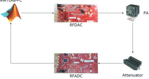
The experimental environment can be described in Fig. 5. The transmitting signal and harmonic canceling signal were sent by a DAC38RF80EVM evaluation module, which can send three different signals at different frequencies. These signals were driven by a 20-W GaN pushpull HPA (V ds= 24 V). This HPA supports the frequency range from 20 MHz to 1000 MHz. The HPA feedback signal attenuated by a 40 dB fixed attenuator was received by an ADC32RF80EVM evaluation module, which also supports receiving three signals at three different frequencies. All signals were processed by MATLAB in a PC.
Figure 5. Experiment setup.
Progress In Electromagnetics Research M, Vol. 65, 2018 161
was 33 dBm. The received signals were aligned with transmitting signals for further signal processing in the PC.
4.2. Modeling Harmonic Distortion with HPA Measured Data
In order to validate the proposed harmonic memory polynomial of Equation (6), the second harmonic distortion was captured when only transmitting signal was sent. The performance of the model can be evaluated by the normalized mean square error (NMSE), which is defined as
NMSE = 10 lg ⎛ ⎜ ⎜ ⎜ ⎜ ⎜ ⎝
L
n=1
|y2(n)−y2(n)|2
L
n=1
|y2(n)|2
⎞ ⎟ ⎟ ⎟ ⎟ ⎟ ⎠
(34)
whereLis the total number of the captured samples andy2(n) the received second harmonic distortion from the output of the HPA, while y2(n) is the estimated second harmonic distortion. NMSE indicates the modeling performance of a polynomial model. Therefore, using measured data, the performance of different polynomial models can be compared as shown in Table 1. All these models have nonlinearity order of 5 and memory depth of 4. In Table 1, the harmonic memory polynomial is significantly better than the memory polynomial, and the harmonic memory polynomial including even order is the best.
Table 1. NMSE of different polynomials.
Polynomials NMSE
Memory polynomial including even order 0.038 dB
Harmonic memory polynomial −18 dB
Harmonic memory polynomial including even order −20 dB
When transmitting signal and harmonic canceling signal are sent, the validity of Equation (7) can also be validated by modeling captured harmonic distortion samples. When using Equation (7), the NMSE of harmonic distortion modeling is −20.93 dB. The power spectrum of modeling error
y2(n)−y2(n) can be shown as Fig. 6. Fig. 6 shows that the modeling error is close to ground noise, which indicates the validity of Equation (7).
Figure 6. Power spectrum of modeling error and second harmonic distortion.
0 200 400 600 800 1000 1200
-130 -120 -110 -100 -90 -80 -70 -60 -50 -40
Error (dB)
The comparison between NFXRLS and NFXAPA
NFXRLS
NFXAPA
Number of adaptation cycles
4.3. Simulation of Comparison between NFX-APA and NFX-RLS
Using computer simulation based on MATLAB, we compare the convergence performances of harmonic canceling system between NFX-APA technique we proposed and NFX-RLS technique extended from NFX-RLS DPD technique [2]. The comparison is shown in Fig. 7, which shows the learning curves on the harmonic canceling problem as the number of adaptation cycles increases. The simulation result shows that NFX-APA has faster convergence than NFX-RLS and better performance than NFX-RLS in the harmonic canceling problem.
4.4. Measured Results of Proposed Algorithm
In order to demonstrate the performance of the method proposed, a concept Harmonic Channel Power Ratio (HCPR) like ACPR is introduced in this test, which can be defined as follows,
HCPR (dBc) = 10log10
Phar Pref
(35)
wherePhar is the power of harmonic channel whose bandwidth is the same as the reference channel, and
Pref is the power of the reference channel. The bandwidth of measured channel is 18.015 MHz, which is the same as ACPR measurement of 20M LTE signal.
As Fig. 4 depicts, transmitting signal and harmonic training signals are firstly sent at 315 MHz, 630 MHz and 945 MHz to model the HPA second harmonic channel and third harmonic channel. The
Frequency (MHz) -100
-90 -80 -70 -60 -50 -40
Power/frequency (dB/Hz)
Power Spectral Density
Before Harmonic Canceling
After Harmonic Canceling
-100 -90 -80 -70 -60 -50 -40
Power/frequency (dB/Hz)
Power Spectral Density
Before Harmonic Canceling
After Harmonic Canceling
(a) (b)
-100 -50 0 50 100
Frequency (MHz)
-100 -50 0 50 100
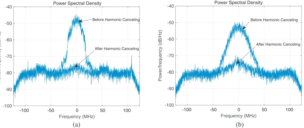
Figure 8. Power spectrum of harmonic distortion before and after harmonic canceling algorithm of NFX-APA for single carrier of LTE-A signal. (a) Second harmonic distortion. (b) Third harmonic distortion.
Table 2. Comparison of HCPRs for 20 MHz LTE-A.
Harmonic Zone Without Cancelling (Lower/Upper)
With Cancelling (Lower/Upper)
Improvement (Lower/Upper) Second Harmonic Zone
(Single Carrier) −35.9349 dB −61.1914 dB 25.2565 dB Third Harmonic Zone
(Single Carrier) −38.1013 dB −60.3233 dB 22.221 dB Second Harmonic Zone
(Dual-Carrier) −38.5906 dB/37.5970 dB −58.3128 dB/58.7049 dB 19.7222 dB/21.1078 dB Third Harmonic Zone
Progress In Electromagnetics Research M, Vol. 65, 2018 163
-100 -95 -90 -85 -80 -75 -70 -65 -60 -55
Power/frequency (dB/Hz)
Power Spectral Density
Before Harmonic Canceling
After Harmonic Canceling
-100 -95 -90 -85 -80 -75 -70 -65 -60 -55
Power/frequency (dB/Hz)
Power Spectral Density
Before Harmonic Canceling
After Harmonic Canceling
Frequency (MHz)
(a) (b)
-100 -50 0 50 100
Frequency (MHz)
-100 -50 0 50 100
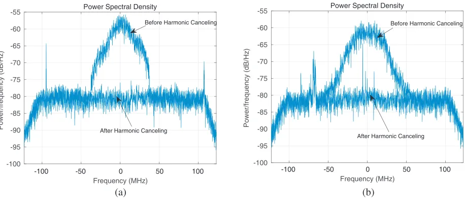
Figure 9. Power spectrum of harmonic distortion before and after harmonic canceling algorithm of NFX-APA for dual-carrier of LTE-A signal. (a) Second harmonic distortion. (b) Third harmonic distortion.
model coefficients were extracted by MATLAB, using 50000 samples. The transmitting signal includes 131072 samples. The nonlinearity orderN1andN2, the memory depth of the model and the predistorter were chosen to beN1= 5, N2 = 2, andD= 4. The power spectrum of the second harmonic frequency and third harmonic frequency before and after NFX-APA for the single carrier and the dual-carrier are shown in Fig. 8 and Fig. 9(b), respectively, and the comparison of HCPRs is shown in Table 2. These measurement results indicate that our method achieves over 20 dB improvement of HCPR for the single carrier, approximately 20 dB for the dual-carrier, which demonstrates the effectiveness of the NFX-APA.
5. CONCLUSION
In this paper, we firstly analyze the out-band harmonic distortion caused by the HPA and find harmonic memory polynomial to model it. After that, we propose the nonlinear filtered-x affine projection algorithm based on the nonlinear adaptive filter to cancel the harmonic distortion. Experimental measurements demonstrate the validity of harmonic memory polynomial and show that the NFX-APA technique achieves remarkable performance. This method is easily implemented in hardware, so it is suitable for the broadband communication, such as 5G communication.
REFERENCES
1. Kim, J. and K. Konstantinou, “Digital predistortion of wideband signals based on power amplifier model with memory,”Electronics Letters, Vol. 37, No. 23, 1417–1418, 2001.
2. Zhou, D. and V. E. De Brunner, “Novel adaptive Nonlinear predistorters based on the direct learning algorithm,” IEEE Transactions on Signal Processing, Vol. 55, No. 1, 120–133, 2007. 3. Changsoo, E. and E. J. Powers, “A new volterra predistorter based on the indirect learning
architecture,” IEEE Transactions on Signal Processing, Vol. 45, No. 1, 223–227, 1997.
4. Morgan, D. R., Z. Ma, J. Kim, M. G. Zierdt, and J. Pastalan, “A generalized memory polynomial model for digital predistortion of RF power amplifiers,”IEEE Transactions on Signal Processing, Vol. 54, No. 10, 3852–3860, 2006.
6. Tsai, H. Y., T. Y. Huang, and R. B. Wu, “Varactor-tuned compact dual-mode tunable filter with constant passband characteristics,” IEEE Transactions on Components, Packaging and Manufacturing Technology, Vol. 6, No. 9, 1399–1407, 2016.
7. Hou, J. A. and Y. H. Wang, “Design of compact 90◦ and 180◦ couplers with harmonic suppression using lumped-element bandstop resonators,”IEEE Transactions on Microwave Theory and Techniques, Vol. 58, No. 11, 2932–2939, 2010.
8. Zheng, S. Y., Z. W. Liu, Y. M. Pan, Y. Wu, W. S. Chan, and Y. Liu, “Bandpass filtering doherty power amplifier with enhanced efficiency and wideband harmonic suppression,”IEEE Transactions on Circuits and Systems I: Regular Papers, Vol. 63, No. 3, 337–346, 2016.
9. Reece, M. A., S. Contee, and C. W. Waiyaki, “K-band gan power amplifier design with a harmonic suppression power combiner,”2017 IEEE Topical Conference on RF/Microwave Power Amplifiers for Radio and Wireless Applications (PAWR), Conference Proceedings, 92–95, 2017.
10. Bassam, S. A., M. Helaoui, and F. M. Ghannouchi, “2-D digital predistortion (2-D-DPD) architecture for concurrent dual-band transmitters,” IEEE Transactions on Microwave Theory and Techniques, Vol. 59, No. 10, 2547–2553, 2011.
11. Pan, W., Y. Liu, and Y. Tang, “A predistortion algorithm based on accurately solving the reverse function of memory polynomial model,” IEEE Wireless Communications Letters, Vol. 1, No. 4, 384–387, 2012.
12. Liu, Y., W. Pan, S. Shao, and Y. Tang, “A new digital predistortion for wideband power amplifiers with constrained feedback bandwidth,”IEEE Microwave and Wireless Components Letters, Vol. 23, No. 12, 683–685, 2013.
13. Muruganathan, S. D. and A. B. Sesay, “A QRD-RLS-based predistortion scheme for high-power amplifier linearization,” IEEE Transactions on Circuits and Systems II: Express Briefs, Vol. 53, No. 10, 1108–1112, 2006.
14. Piazza, R., M. R. B. Shankar, and B. Ottersten, “Data predistortion for multicarrier satellite channels based on direct learning,” IEEE Transactions on Signal Processing, Vol. 62, No. 22, 5868–5880, 2014.
15. Sun, G., C. Yu, Y. Liu, S. Li, and J. Li, “An accurate complexity-reduced simplified Volterra series for RF power amplifiers,”Progress In Electromagnetics Research C, Vol. 47, 157–166, 2014. 16. Lei, D., G. T. Zhou, D. R. Morgan, Z. Ma, J. S. Kenney, J. Kim, and C. R. Giardina, “A
robust digital baseband predistorter constructed using memory polynomials,” IEEE Transactions on Communications, Vol. 52, No. 1, 159–165, 2004.
17. Nghe, C. T., D. Maassen, X. A. Nghiem, and G. Boeck, “Ultra-wideband efficient linearized 10W GAN-HEMT power amplifier,” 2017 IEEE International Symposium on Radio-Frequency Integration Technology (RFIT), Conference Proceedings, 189–191, 2017.
18. Benedetto, S., E. Biglieri, and R. Daffara, “Modeling and performance evaluation of Nonlinear satellite links-a Volterra series approach,”IEEE Transactions on Aerospace and Electronic Systems, Vol. 15, No. 4, 494–507, 1979.
19. Ding, L. and G. T. Zhou, “Effects of even-order nonlinear terms on power amplifier modeling and predistortion linearization,” IEEE Transactions on Vehicular Technology, Vol. 53, No. 1, 156–162, 2004.
20. Hussein, M. A., V. A. Bohara, and O. Venard, “On the system level convergence of ILA and DLA for digital predistortion,”2012 International Symposium on Wireless Communication Systems (ISWCS), Conference Proceedings, 870–874, 2012.
21. Lim, Y. H., Y. S. Cho, I. W. Cha, and D. H. Youn, “An adaptive nonlinear prefilter for compensation of distortion in nonlinear systems,”IEEE Transactions on Signal Processing, Vol. 46, No. 6, 1726–1730, 1998.
22. Haykin, S. O.,Adaptive Filter Theory, Pearson Higher Ed., 2013.
23. Sankaran, S. G. and A. A. Louis Beex, “Convergence behavior of affine projection algorithms,”