Available Online at www.ijcsmc.com
International Journal of Computer Science and Mobile Computing
A Monthly Journal of Computer Science and Information Technology
ISSN 2320–088X
IMPACT FACTOR: 6.017IJCSMC, Vol. 7, Issue. 4, April 2018, pg.173 – 182
OPTICAL PACKET SWITCHING
BASED ON TURBO SWITCHES
USING SPACE SWITCH ARRAY
Suhail Ashraf
M.Tech CSE, CCNA
(Assistant Professor Department of CSE, SSM College of Engineering & Technology, Pattan J&K)
Abstract: Optical packet switching based on turbo switches using space switch array is Simulation
of a 4 x 4 optical packet space switch array based on Turbo-Switches were carried out on The
OptSim simulator was used to model the structure, to assess the behavior and performance of this
switch array. Parameters such as Q factor and bit error rate (BER), jitter were calculated.
Transparent space switch array is an enabling technology for implementing OPS.
Introduction
With respect to switching and routing, OTNs are grouped into two major categories:
1. Opaque/Translucent Networks - The routing and switching is performed electronically, thereby
requiring signal regeneration, which in turn involves multiplexing/de-multiplexing and amplification before the signal is launched to the next node.
2. Transparent Network- it does not need signal regeneration, and all optical switching, routing, and
amplification is implemented and transport is achieved between the nodes as if the nodes were transparent. All-optical space switch arrays (OOO cross-connects) are the most important elements of a transparent network. They switch data without any conversions to electrical form. The core of an OOO cross-connect is an optical switch that is independent of data rate and data protocol, making the connect ready for future data-rate upgrades. Other advantages of OOO cross-connects include reductions in cost, size, and complexity. Data to be transmitted is generated using p-n sequence generator is given to CW laser operating at1550nm.Then the signal is given to SOA which acts as a switch according to the junction current. The select or combiner is used for selecting the path and the data reaches at the output port. OptSim is an advanced optical communication system simulation package designed for professional engineering and cutting-edge research of emerging optical systems in telecom, data comm, and the simulation schematic of the 4 x 4 space switch. Routing is realized by applying currents to turn on the relevant gates along the route. In the absence of a current, the signal is suppressed to a very low level (about – 50dB), which effectively reduces crosstalk.
A Turbo-Switch scheme. A DISC filter is placed after the turbo switch for wavelength conversion
The simulation diagram for 4X4 space switch array is shown in Fig. The performance of 4X4 space switch array was analyzed using an input data rate of 10Gbps and the Eye Diagrams were observed at four output nodes. Eye Diagrams thus obtained were studied and the corresponding output parameters were noted. After having successfully achieved optimum BER and quality it can be used to design optical communication systems. Simulation can be done to determine their performance given various component parameters to guarantee the highest possible accuracy and real-world results.
STUDY OF COMPONENTS AND DIAGRAMS USED
Design of a free space optical switch demonstrator for a VCSEL-based
photonic packet switch
Free space chip-to-chip optical interconnections might be considered as a means of increasing the scalability of large electronic IP switches. In one category of hardware implementation some channel selection takes place in the optical interconnect, which employs optical fan-out, selection of channels followed by optical fan in. We have discussed a version of the architecture in which liquid crystal over silicon devices were used as input transducers to modulate the optical channels and to reconfigure the interconnect. The slow speed of the modulators (100 kHz) meant that massive parallelism was necessary in the optics (107 channels) to achieve a capacity of a Tb/s. The fan-in optics for such systems appear to be formidable. One possible solution is to use a much smaller number of higher data rate optical channels using VCSELs. This assumes that the problems of integrating the VCSEL array and suitable photo detectors with high-density silicon CMOS circuitry can be solved, but it reduces the optics to manageable proportions. It is
our estimate that switch modules with capacity approaching 1 Tb/s could be constructed with 16 x 16 array of polarisation-stable VCSELs operating at around 2 Gbits/s with a fan-out of 16. Switches comprised of such modules might be scalable into the Pb/s region. In the implementation considered here, the links will be reconfigured using a miniature free space optical interconnect based on liquid crystal (LC) shutters. An earlier system of this kind (for fibre to fibre switching) reconfigured 64 channels in 17 s. Here we aim to reconfigure 16 channels in 1 s to minimise queuing on the input plane of the switch.
System design and device experiments
microstrip design concept has been used for the Hamamatsu chip. A 40-dB gain amplifier complements the detector.
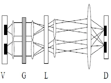
The layout of the switch is shown in Fig 1. Four 2 x 2 sub-arrays of VCSELs are fanned out in a classic 4f arrangement with the grating in the mid-plane. Each 2 x 2 sub-array has a dedicated 4f arrangement. At the image plane of each 4f system, 4 2 x 2 sub-arrays are formed. Because these are within the aperture of a micro-optical system, aberrations are reduced compared to larger offaxis multiple imaging arrangements. The fast shutter plane, which is placed in the image plane of the 4f systems, blocks all but one of the 2 x 2 sub-arrays in each aperture. The fan in, which is accomplished by a lenslet array with a single compound lens, reconstitutes a 4 x 4 array using the 4 2 x 2 sub-arrays which have been selected by the shutter array.
Fig 1 The optical system of the demonstrator (V-plane of VCSEL arrays; G-Diffractive grating;
L-Liquid crystal shutter array; D-plane of detector arrays)
4 shutter array of which the 4 central pixels are transmissive will create the arrangement of sectors in the detector plane shown in Fig. 2. Here, we just show one of the possible combinations of the output. There are 4! possible arrangements for the sectors in the detector plane. The fan-out/fan-in losses associated with this system scale as the fan-out rather than the number of input channels. One purpose of the demonstrator will be to help assess the limits of sectorised switching. We believe that this design concept is scalable up to a Tb/s switch module. Higher switch capacities will require the optical interconnection of such modules. V G L D In order to specify the shutter array, we have constructed liquid crystal test cells with several types of liquid crystal. In our previous measurements [5], we used an experimental electroclinic mixture FELIX-R1305(Clariant, Japan) which is no longer available. Thus, we have used another experimental electroclinic mixture FELIX-R1306 (Clariant, Japan) which can be supplied subsequently. This mixture has a SmA phase between 31.9 C and 65.8 C. We measured a field induced tilt angle of 11 with 1 s electro-optic response time at 45 C using an electric field of 20V/ m across a 1.0 m cell. The Contrast Ratio (CR) (TON /TOFF ) of the shutter is highly dependent on the OFF-state transmission (TOFF) of the LC between a polariser/analyser pair. The quality of alignment of the LC is important for achieving low TOFF. The CR and the loss specifications will be achieved, by operating the link with nearly crossed analyser. If the angle of the analyser from the crossed position is 3 deg and we use a field of 20V/ m across the LC cell, then the ON-state loss will be 7.5 dB and the CR will be 66. We measured the CR as 58, which is close to the calculated value. Although electroclinic liquid crystals are a good choice for fast switches due to the low viscosity of director rotation, special measures have to be taken in order to ensure that current flow into the cell does not induce chemical degradation of the liquid crystal when a DC voltage is applied across the cell over a considerable time. We plan to reduce DC currents by introducing a passivation layer of silica over the ITO electrodes.
Conclusion
The main objective is to improve the performance of the current system by implementing some modification of the current switching elements. One such arrangement, known as Turbo-Switch which uses two SOAs and a filter as the basic switching element can be implemented. The recovery time of a Turbo-Switch is less as compared to SOA and hence higher switching speeds can also be achieved.
Results
order to prevent such patterning, a faster response speed is generally required. Recently, various linear spectral filtering schemes [6-8] have been reported which greatly increase the observed response speed. Another scheme giving a faster response incorporates a second SOA in the so-called Turbo-Switch arrangement, in which the second SOA may be loosely regarded as a filter. Whilst these approaches help to increase the operating speed of the optical switching, they do not reduce the actual recovery time of the gain of the SOA.
References
[1] Ni Yan, “Simulation of 4 x 4 Optical Packet Space Switch Array Department of Electronic and Electrical Engineering, University College London”.
[2] Arun K. Somani, Byrav Ramamurthy, “Optical Communication Networks for Next-Generation Internet”, CSE Journal Articles. Paper 77
[3] Georgios I. Papadimitriou, Senior Member, IEEE, Chrisoula Papazoglou, and Andreas S. Pomportsis, Member, IEEE," Optical Switching: Switch Fabrics, Techniques, and Architectures ", Journal Of Light wave Technology, Vol. 21, No. 2, February 2003
[4] OptSim Study guide by Rsoft Design Group Inc.
[5] Demonstration of Asynchronous Operation of a Multiwavelength Optical Packet-Switched Fabric Caroline P. Lai, Student Member, IEEE, AssafShacham, Member, IEEE, and Keren Bergman, Fellow, IEEE, IEEE PHOTONICS TECHNOLOGY LETTERS, VOL. 22, NO. 16, AUGUST 15, 2010.
[6] Y. Liu, et al.: Error-free 320Gbit/s SOA based Wavelength Conversion using Optical Filtering, in Proc. OFC/NFOEC, Anaheim, CA, USA 2006, paper PDP28.
[7] M. Nielsen and J. Mork: Increasing the modulation bandwidth of semiconductor-optical-amplifier-based switches by using optical filtering, J .Opt. Soc. Am. B, vol. 21, pp. 1606-1619, Sept. 2004.
[8] J. Leuthold: Trends in the Field of All-Optical Wavelength Conversion and Regeneration for Communication up to 160 Gbit/s, in Proc. ECOC, Glasgow, 2005, paper Tu3.3.6.
[9] Gregory A. Fish, Beck Mason, Larry A. Coldren, and Steven P. DenBaars," Compact, 4X 4 InGaAsP– InP Optical Cross connects with a Scalable Architecture ", IEEE photonics technology letters, vol. 10, no. 9, September 1998
[10] R.J. Manning, et al.: Cancellation of Nonlinear Patterning in Semiconductor Amplifier Based Switches, in Proc. OAA, Whistler, Canada, 2006, paper OTuC1.
[11] R. Giller, et al.: Recovery Dynamics of the „Turbo-Switch, in Proc. OAA, Whistler, Canada, 2006, paper OTuC2.
[12] R.J. Manning, et al.: Semiconductor laser amplifiers for ultrafast all-optical signal processing, J. Opt. Soc. Am. B, vol. 14, pp. 3204-3216, 1997.
[13] L. Zhang, et al.: Significant reduction of recovery time in semiconductor optical amplifier using p type modulation doped
[14] B. Dagens, et al.: Design optimization of all-active Mach- Zehnder wavelength converters, Phot. Tech. Lett., vol. 11, pp. 424-426, Apr. 1999.
[15] Y. Miyazaki, et al.: Polarization-Insensitive SOA-MZI Monolithic All-Optical Wavelength Converter for Full C- band 40Gbps-NRZ Operation, in Proc. ECOC, Cannes, France, 2006, paper Th3.4.2.
[16] R. Giller, et al.: Analysis of the dimensional dependence of semiconductor optical amplifier recovery speeds, Optics Express, vol. 15, pp. 1773-1782, Feb. 2007
[18] Ellinas J. Labourdette, J. Walker, S. Chaudhuri, L. Lin, E. Goldstein, K. Bala, “Transparent Optical Switches: Technology Issues and Challenges”.
[19] George N. Rouskas, LisongXu, “Optical Packet Switching”, Department of Computer Science,North Carolina State University.
[20] Gregory A. Fish, Beck Mason, Larry A. Coldren, and Steven P. DenBaars," Compact, 4X 4 InGaAsP–InP Optical Cross connects with a Scalable Architecture ", IEEE photonics technology letters, vol. 10, no. 9, September 1998
[21] David K. Hunter, Meow C. Chia, and Ivan Andonovic," Buffering in Optical Packet Switches ", Journal
[22] LIGHTWAVE TECHNOLOGY, VOL. 27, NO. 3, FEBRUARY 1, 2009
[23] D. Cuda, R. Gaudino, G.A. Gavilanes, F. Neri, G. Maier, C. Raffaelli, M. Savi, " Capacity/Cost Tradeoffs in Optical Switching Fabrics for Terabit Packet Switches", International
[24] Conference on ONDM, 18-20 February 2009 24. G. I. Papadimitriou, P. Tsimoulas, M. S. Obaidat, and A. S. Pomportsis, Multiwavelength Optical LANs. New York: Wiley, 2003
[25] G. I. Papadimitriou and A. S. Pomportsis, “Self-Adaptive TDMA protocols for WDM star networks: A learning- automata-based approach,” IEEE Photon. Technol. Lett., vol. 11, pp. 1322– 1324, Oct. 1999.
[26] C. Siva Ram Murthy and Mohan Guruswamy, “WD Optical Networks: Concepts, Manning Design and Algorithms”, Prentice Hall PTR, 2002.
[27] Masatoshi Saruwatari," All-Optical Signal Processing for Terabit/Second Optical Transmission", IEEE JOURNAL ON SELECTED TOPICS IN QUANTUM ELECTRONICS, VOL. 6, NO. 6, NOVEMBER/DECEMBER 2000.
[28] Arun K. Somani, Byrav Ramamurthy, “Optical Communication Networks for Next-Generation Internet”, CSE Journal Articles. Paper 77
[29]http://www.scribd.com/doc/40723745/Detecon-Opinion- Paper-Photonic-Packet-Switching-and-the-Evolution-of- Optical-Networks
[30]http://klamath.stanford.edu/~molinero/thesis/html/pmf_thesis _node40.html
[31]https://code.ua.pt/projects/bookco1011/wiki/_1242_Optical_packet_Switching_%28OPS%29 [32]http://en.wikipedia.org/wiki/Optical_ switch
[33] M. P. Dames, J. R. Collington, W. A. Crossland and R. W. A. Scarr, ‘Three-stage high performanceopto-electronic asynchronous transfer mode switch: design and performance.’ Optical Engineering, 35, pp. 3608-3616, (1996).
[34] C. W. Wilmsen, C. Duan, M. P. Dames, J. R. Collington, W. A. Crossland, ‘Vertical cavity surface emitting laser based optoelectronic asynchronous transfer mode switch.’ Optical Engineering, 38, pp. 1216-1221, (1999).
[35] N. Collings, W. A. Crossland, T.D. Wilkinson, R. W. A. Scarr, T. J. Hall, ‘Packet switching network based on optical fan in’, Proc. SPIE 4089, pp. 550-554 (2000).
[36] HJ White, CP Barrett, MJ Birch, JR Brocklehurst, NA Brownjohn, WA Crossland, AB Davey, DM Monro, DT Neilson, JA Nicholls, GM Proudley, B. Robertson, RWA Scarr, M Snook, C Stace, MR Taghizadeh, D Vass and AC Walker. “An optically connected parallel machine: design performance and application.” IEE Proc.- Optoelectronics, 146, No. 3 March 1999, pp 1-12.