201 |
P a g e
EXPERIMENTAL STUDY ON SUBCOOLED FLOW
BOILING OF WATER INSIDE A THREADED TUBE
WITH DIFFERENT TUBE INCLINATIONS
F.S. Tanekhan
1, R. M. Warkhedkar
2, A.T.Pise
31,
PG Student,
2,Associate Professor, Department of Mechanical Engineering,
Government College of Engineering, Karad, (India)
3,
Deputy Director of DTE, Maharashtra, (India)
ABSTRACT
The objective of this paper is to investigate the influence on heat transfer coefficient of subcooled boiling of water inside a copper threaded tube at five different angles between 00& 900. The experimental data were obtained over a heat fluxes range from 17 kW/m2 to 114 kW/m2and mass fluxes range of 100 kg/m2s to 300 kg/m2s. The specifications of test section were as follows: length of test section, 1000 mm; outside diameter, 9.52 mm; inner diameter,7.52 mm; bottom wall thickness, 0.76 mm; tooth depth, 0.24 mm; tooth apex angle, 600; helix angle, 250. The influences of above parameters on the heat transfer coefficient with tube inclinations are presented. The heat transfer coefficients predicted by some available correlations are compared with the present data.
Keywords: Flow boiling, Subcooled, Inclined, Internal Threaded Copper Tube
I. INTRODUCTION
Flow boiling has long played a major role in many industrial applications due to its superior heat transfer
performance such as water tube boilers, evaporators, nuclear power plants and high density electronic
components. Boiling is a very complex process due to heterogeneous nature of heat transfer medium. In
subcooled boiling vapour bubbles generates at the heater surface while the bulk temperature of the liquid is still
below the saturation temperature. Bubbles detaching from the heated surface collapse and condense in the
subcooled liquid bulk. Also the use of augmentative techniques, either active or passive, to increase heat transfer
coefficient has been studied so many times. One of the passive techniques to enhance heat transfer coefficient is
the applications of internally threaded tube. Internally threaded tube can increase heat transfer through creating
turbulence and limiting the growth of thermal boundary layer by slight increase in pressure drop. Many
researchers have conducted experimental studies with or without passive techniques. Also the heat transfer
characteristics generally keeps changing as the flow pattern changes inside the test section in the other hand the
IJARSE, Vol. No.4, Issue 04, April 2015 ISSN-2319-8354(E)
202 |
P a g e
Nomenclature
Bo Bond number
Inner diameter (mm)
Outer diameter (mm)
Fr Froude number G Mass flux (kg/ m2 s)
I Current (A)
k Thermal conductivity of copper (W/m0C) Thermal conductivity of water (W/ m0C)
l Length of test section (mm)
M Mass flow rate (kg/s)
Nu Nusselt number
Number of grooves
Prandtl number of water
Q Heat flow (W)
Heat flux (W/ m2)
Equivalent Reynolds number
Rx Geometry enhancement factor
Fluid temperature (0C)
Inlet temperature of water (0C)
Outlet temperature of water (0C)
Inner surface temperature (0C)
Outer surface temperature (0C)
Average outer surface temperature (0C)
Velocity of gas phase with total flow rate (m/s)
V Voltage (V) x Quality
μ Dynamic viscosity (Pa s)
g Gravity
α Heat transfer coefficient (W/m2 0C)
Density of water (kg/m3)
Density of vapour (kg/m3)
Surface tension (N/ m)
Apex angle
203 |
P a g e
II. LITERATURE SURVEY
As an example of conducted researchers, Sarafraz et al.[1] experimentally studied flow boiling heat transfer of
dilute water- diethylene glycol mixtures inside a vertical annulus. He investigated the influence of heat flux,
flow velocity, degree of subcooling and concentration of mixture on heat transfer coefficient in both the
convection and nucleate boiling regimes. Barbosa et al. [2] conducted experiments in a vertical annulus in which
heat was applied to the inner surface of the tube. A dominance of nucleate boiling was observed at low qualities.
At high qualities, nucleate boiling was partly or totally suppressed and forced convection became the dominant
mechanism. Thus, one may conclude that in internal flow boiling, the heat transfer coefficients a combination of
two mechanisms: nucleate boiling and forced convection. Bin sun et al. [3] experimentally studied the flow
boiling heat transfer characteristics of four nanorefrigerants in an internal threaded tube. They found that
maximum heat transfer coefficient of four kinds of nanorefrigerants increased by 17-25%and the heat transfer
coefficient increased by 3-20%.Akhvanbahabadi et al. [4] experimentally investigated evaporation heat transfer
of R-134a inside a microfin tube for seven different tube inclinations ranging from -900 to +900. Results showed
that at low vapour qualities the highest heat transfer coefficient was attained at +900& at higher vapour qualities
the highest heat transfer coefficient when tube is horizontal or was inclined at -300. The vertical tube with
inclination angle of 900 had the lowest heat transfer coefficient for entire range of vapour quality. Arijit kundu et
al. [5] studied the heat transfer characteristics of R-407 inside smooth tube with different tube inclinations
angles from 00-900. They found that heat transfer coefficient increases with mass flux and heat flux. The tube
inclination angle affects heat transfer coefficient in a significant manner for the inclination of 900 the highest
heat transfer was attained. Akhvan bahabadi et al. [6] studied experimentally evaporation heat transfer of
R-134a inside a corrugated tube for seven different tube inclinations ranging from -900 to +900. They found that
for low vapour quality region heat transfer coefficient for +900 inclined tube was about 62 % more than that of
-900 inclined tube. Also for all mass velocities, the highest heat transfer coefficient were achieved for +900.
III. EXPERIMENTAL METHOD
3.1 Experimental Set-up
The schematic diagram of test apparatus has been shown in fig.1. It consists of a pre-heater, a pump, a
rotameter, a test section, and water cooled condenser. Initially the fluid is heated in preheater at 800C, then that
fluid flows to test section through rotameter. The liquid- vapour mixture that outflowed from test section flowed
into the condenser, where it is condensed into liquid. The condensed liquid passed through circulation pump to
pre- heater. The pre-heater consists of a tank with 1.5 kW capacity heater was installed in it and constant AC
supply was given for preheating the fluid. The test section was heated by a flexible nichrome heater wire (of 4
kW capacity) wrapped around the outside of test tube. Heat flow to heater wire was monitored with a variety
AC voltage controller. The voltage and current flow was measured by analog meter to determine applied heat
IJARSE, Vol. No.4, Issue 04, April 2015 ISSN-2319-8354(E)
204 |
P a g e
Fig.1Schematic Diagram of Experimental Setup
3.2 Test Section
The test section was made of copper tube. The specifications of test section were as follows: length of test
section, 1000 mm; outside diameter, 9.52 mm; inner diameter, 7.52 mm; bottom wall thickness, 0.76 mm; tooth
depth, 0.24 mm; tooth apex angle, 600; helix angle, 250. The test section was heated by a flexible nichrome
heater wire (of 4 kW capacity) wrapped around the outside of test tube, and five cross sections without heater
wire are reserved in order to adhere thermocouples, as shown in fig. 2. Ten K- type thermocouples are located at
top and bottom sides of above five cross sections of the test tube to measure the outside tube wall temperatures.
The test section was insulated with ceramic wool to reduce heat loss to the surroundings. Also two
thermocouples and one pressure sensor to measure temperature and pressure of fluid are installed at inlet and
outlet of test section respectively.
Fig.2 The Test Section and Layout (unit: mm)
3.3. Procedure
The heat transfer coefficient was calculated by using following equation,
Where q is the heat flux (W/m2), is the inner surface temperature (oC), and is the fluid temperature (oC)
205 |
P a g e
where is the inlet temperature (oC) and is the outlet temperature (oC) of fluid. As the outside wall
temperature of the test section was measured at five axial locations. At each location, the temperature of the tube
was measured at top and bottom positions.
Thus, the average outside tube wall temperature of the test section, , was calculated as the arithmetic mean of
outside tube wall temperature at five axial locations.
Thermal resistance was used to measure the outside surface temperature of the tube, but the inner surface
temperature was required to calculate the heat transfer coefficient. Therefore, according to Fourier’s
one-dimensional, radial, steady-state heat conduction equation for a hollow cylinder, based on the assumption that
the heat flux is uniform inside the tube and a negligible heat loss to the surroundings, the inner surface
temperature was calculated as follows:
Where is the outer diameter (mm), is the inner diameter (mm), is the thermal conductivity of copper
(W/moC), is the length of the test section (mm), and is the heat flow to the test section (W) calculated
from the voltage (V) and current (I) of the test section.
3.4 Experimental data validation
To verify the experimental data, obtained results for pure water have been compared with known correlations
for the horizontal position (Ɵ = 00) of test section. To examine the verification of obtained data related to
single-phase convection region, Sider-Tate equation has been employed. Sider- Tate equation for predicting the forced
convection heat transfer coefficient as follows [7]:
Results of this comparison demonstrate the well agreement of about 16% between the experimental data and the
calculated results for single- phase convection zone. To examine the verification of obtained data related to
nucleate boiling region, the experimental results of pure water were compared with the results obtained using
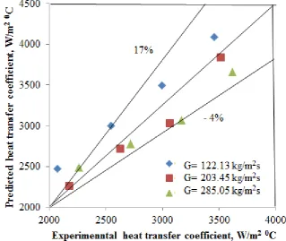
the formula of Cavallini et al. [8]. The Cavallini pure working fluid experimental correlation is as follows:
IJARSE, Vol. No.4, Issue 04, April 2015 ISSN-2319-8354(E)
206 |
P a g e
Results of this correlation express the agreement about +17% to - 4%with the experimental data. Fig. 3 and fig.
4 shows the result of comparison between experimental data related to pure water and well known correlations
respectively.
Fig. 3 Comparison of results obtained by Sider-Tate equation and experimental data in forced convective
region
Fig. 4 Comparison of results obtained by Cavallini correlation and experimental data in nucleate boiling
207 |
P a g e
IV. RESULT AND DISCUSSION
The fluid enters the test section at 800C temperature. So the degree of subcooling (ΔT=200C) is kept constant for
whole experiment. In flow boiling two different regions of heat transfer has been considered: (1) convective
region & (2) nucleate boiling region. There are many parameters affecting the flow boiling heat transfer
coefficient. Accordingly, effect of heat flux, flow rate and inclination angle of test tube are separately discussed.
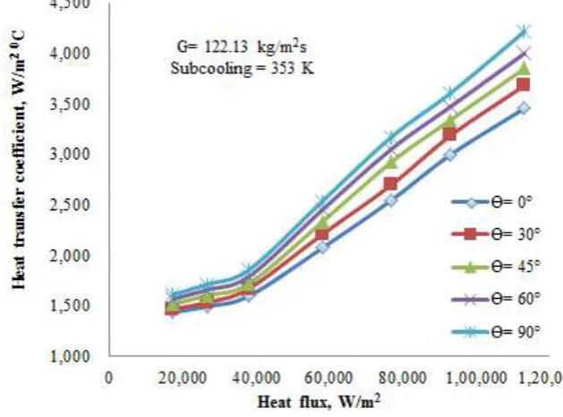
4.1. Effect of Heat Flux
Experimental data are shown in terms of heat transfer coefficient vs. heat flux. As shown in fig. 4, fig. 5 and fig.
6, with increasing heat flux, the flow boiling heat transfer coefficient increases. These increases are clearly
observable in both convective and nucleate boiling zones. For convective heat transfer zone increase of heat
transfer coefficient with heat flux is insignificant in comparison with nucleate boiling zone. In fig. 4, 5 and 6 for
five different angle of test section, influence of heat flux on heat transfer coefficient is shown. As seen in
convective zone, slope of changes of flow boiling heat transfer coefficient is less than that in nucleate boiling
zone. The main reason for this is, at lower heat fluxes where no bubbles generated, hence lower heat transfer
coefficient. As heat flux increases, the rate of bubble generation around the heated surface increases, so that
there is rigorous interaction between bubbles at heated surface which induce the locally turbulence agitations
and this results in heat transfer enhancement.
IJARSE, Vol. No.4, Issue 04, April 2015 ISSN-2319-8354(E)
208 |
P a g e
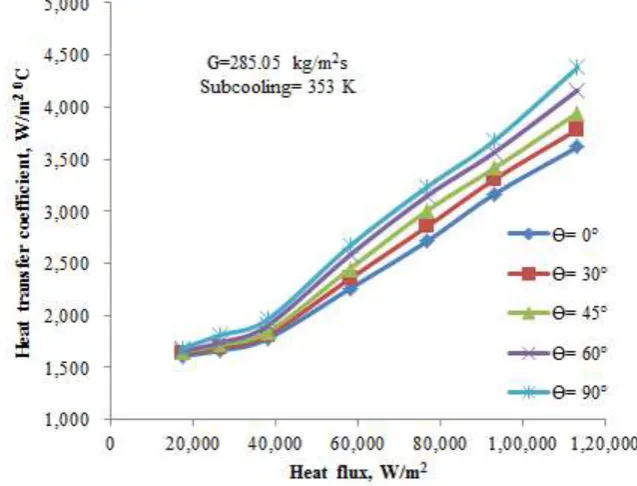
Fig. 6 Effect of heat flux and inclination angle of test section on heat transfer coefficientFig. 7 Effect of heat flux and inclination angle of test section on heat transfer coefficient
4.2. Effect of Mass Flux
As in fig. 4, fig. 5 and fig. 6, flow boiling heat transfer coefficient increase with increasing mass flux in both
convective and nucleate boiling regions. At all the mass fluxes the increase in the heat transfer coefficient in the
nucleate boiling region is considerably higher than in the convective region. Also as the mass flux increases the
difference in heat transfer coefficient for different inclination of tube goes on reducing in convective region. In
nucleate boiling region, for vertical upward flow (Ɵ= 900) the heat transfer coefficient increases with 4% for
209 |
P a g e
4.3. Effect of Inclination Angle of Test Section
As shown in fig. 4, fig. 5, and fig. 6, as the inclination angle increases the heat transfer coefficient also
increases. For all flow rates, the increase in heat transfer coefficient with inclination angle 900in comparison
with other inclination angles is probably due to the favourable flow of liquid inside grooves in convective region
and due to high interfacial turbulence, also buoyancy force and fluid flow are unidirectional in nucleate boiling
region, as a result the flow accelerates enhancing heat transfer from heated wall of the tube.
V. CONCLUSION
The effects of variation in heat fluxes, mass fluxes of water and inclination angle of test section on heat transfer
coefficient were investigated experimentally inside threaded copper tube. The conclusions of this study can be
summarized as follows:
1. The experimental results indicate that for all tube inclination angles, the heat transfer coefficient increases
with heat flux and mass flux in both forced convective and nucleate boiling region.
2. The effect of tube inclination is also much more severe on the heat transfer coefficient. As the inclination
angle increases the heat transfer coefficient also increases.
3. The highest heat transfer coefficient is attained at inclination angle of 900 (vertical upward flow).
REFERENCES
[1] M.M. Sarafraz, S.M. Peyghambarzadeh, “Experimental study on subcooled flow boiling heat transfer to
water–diethylene glycol mixtures as a coolant inside a vertical annulus”, Experimental Thermal and
Fluid Science, Vol. 50 (2013) 154–162.
[2] J.R. Barbosa, G.F. Hewitt, S.M. Richardson, “High-speed visualization of nucleate boiling in vertical
annular flow”, International Journal of Heat and Mass TransferVol. 46 (2003) 5153–5160.
[3] B. Sun, D. Yang, “Experimental study on the heat transfer characteristics of nanorefrigerants in an internal thread copper tube”, International Journal of Heat and Mass Transfer, Vol. 64 (2013)559–566.
[4] M.A. Akhavan-Behabadi, S.G. Mohseni, S.M. Razavinasab, “Evaporation heat transfer of R-134a inside
a microfin tube with different tube inclinations”, Experimental Thermal and Fluid Science, Vol. 35
(2010) 996–1001.
[5] ArijitKundu, Ravi Kumar, Akhilesh Gupta, “Flow boiling heat transfer characteristics of R407C inside a
smooth tube with different tube inclinations”, International Journal of Refrigeration, Vol. 45 ( 2014 ) 1-1
2.
[6] M.A. Akhavan-Behabadi, M. Esmailpour, “Experimental study of evaporation heat transfer of R-134a
inside a corrugated tube with different tube inclinations”, International Communications in Heat and
Mass Transfer, Vol. 55 (2014) 8–14.
[7] J. B. Copetti, M. H. Macagnan, D. De Souza, R. De Césaro Oliveski, “Experimental study on thermal
and hydraulic behavior of micro-fin tubes in single phase”, 17th International Congress of Mechanical
Engineering, November (2003) 10-14, São Paulo, SP.
[8] A.Cavallini, D. Del Col, L. Doretti, G.A. Longo, L. Rossetto, “Heat transfer and pressure drop during
condensation of refrigeration inside horizontal enhanced tubes”, International Journal of Refrigeration,
IJARSE, Vol. No.4, Issue 04, April 2015 ISSN-2319-8354(E)
210 |
P a g e
[9] A.Kundu, R. Kumar, A. Gupta, “Evaporative heat transfer of R134a and R407C inside a smooth tube
with different inclinations”, International Journal of Heat and Mass Transfer, Vol. 76 (2014) 523–533.
[10] M.A.Akhavan-Behabadi, Ravi Kumar, S.G.Mohseni, “Condensation heat transfer of R-134a inside a
microfin tube with different tube inclinations”, International Journal of Heat and Mass Transfer, Vol. 50