Effect of time on a hierarchical corn skeleton-like composite of
CoO@ZnO as capability electrode material for high specific
performance supercapacitors
Anil Kumar Yedluri* and Hee-Je Kim
School of Electrical Engineering, Pusan National University, Busandaehak-ro 63beon-gil,
Geumjeong-gu, Busan, 46241, Rep. of KOREA
*Corresponding Author. Tel: +82 51 510 2364. Fax: +82 51 513 0212. E-mail:
[email protected] (H.-J. Kim): [email protected] (A. K. Yedluri)
Abstract:
CoO-ZnO-based composites have attracted considerable attention for thedevelopment of energy storage devices because of their multifunctional characterization and ease
of integration with existing components. This paper reports the synthesis of CoO@ZnO (CZ)
nanostructures on Ni foam by the CBD method for facile and eco-friendly supercapacitor
applications. The formation of a CoO@ZnO electrode functioned with cobalt, zinc, nickel and
oxygen groups was confirmed by X-ray diffraction, X-ray photoelectron spectroscopy, low and
high-resolution of scanning electron microscopy, and transmission electron microscopy. The
as-synthesized hierarchical nanocorn skeleton-like structure of CoO@ZnO-3h (CZ3h) electrode
delivered a higher specific capacitance of 1136 F/g at a current density of 3 A/g with outstanding
cycling stability, showing 98.3% capacitance retention over 3000 cycles in an aqueous 2 M KOH
electrolyte solution. This retention was significantly better than that of other prepared electrodes,
such as CoO (CO), ZnO (ZO), CoO@ZnO-1h (CZ1h), and CoO@ZnO-7h (CZ7h) (274, 383, 240
and 537 F/g, respectively). This superior capacitance was attributed to the ideal surface
morphology of CZ3h, which is responsible for the rapid electron/ion transfer between the
electrolyte and electrode surface area. The enhanced features of the CZ3h electrode highlight
potential applications in high performance supercapacitors, solar cells, photocatalysis, and
electrocatalysis.
Keywords:
Nanorod structure; NanoCorn structure; Hierarchical nanocorn skeleton-likeIntroduction
In recent years, with the increasing energy and power demands of the modern world, the
continuous depletion of fossil energy, and continuous growing of the global economy, has
prompted considerable interest in the generation of renewable clean and efficient energy, in terms
the management, storage, and production of this precious energy [1-4] . Among the various types
of electrical energy storage, electrochemical capacitors (ECs) or ultra-capacitors have attracted
enormous research and industrial attention because of their high charge-discharge current
capability, high power density, very high efficiency, stable cycling performance environmental
friendly and temperature range compared to fuel cells [5]. Batteries have higher energy density
over traditional capacitors and conventional dielectric capacitor [6,7]. Therefore, considerable
research is being directed towards the development of supercapacitors with the overall goals of
increasing the energy density with minimal sacrifice of the very high power density and cycle life
[8,9].
Supercapacitors are used widely in high power applications, such as portable electronic
devices, renewable energy storage devices, and hybrid electric vehicles [10]. Currently, the
research into supercapacitors has focused mainly on the specific energy of supercapacitors,
electrode materials as well as their micro or nano morphology [11]. Moreover, continuous efforts
have been devoted to designing high performance electrode materials with stability and high
capacitance, and electrolyte and assembly technology [12-14]. Hence, the study of electrode
materials has become a field of intense research activity [15].
Supercapacitors can be classified two categories based on the energy storage mechanism:
capacitors (EDLCs) [16,17]. In EDLCs, carbon-based materials are commonly used in
supercapacitor electrodes owing to their high power density, low cost, controllable porosity, and
ease of process ability [18]. On the other hand, the relatively low energy density, low specific
capacitance, and volumetric capacitance have limited their practical use for high performance
supercapacitors [19-21]. Some carbon-based materials, such as carbon nanotubes, activated carbon,
and graphene, have been used as electrode materials [22]. Nevertheless, in recent years, extensive
attention has been paid to the surface area of the electrode [23]. In terms of pseudocapacitance,
transition materials can have better capacitive performance than carbon-based EDLC electrodes,
resulting from the interface and they are thus categorized as supercapacitors. Pseudocapacitor
materials contain metal oxides and sulfides, particularly metal oxide materials with higher specific
capacitance, such as CoO, MnO2, Fe2O3, and Co3O4 [24]. They have been considered promising
anode materials compared to other pseudocapacitor materials and show more stable performance
than carbon materials, which can result in a much higher specific capacitance and energy density
because they can supply different oxidation states for efficient redox reactions [25]. Among the
various metal oxides, CoO is an ideal supercapacitor electrode material that has been shown to be
a promising electrode material for various applications due to the high redox reactivity, good
electric conduction, low cost, high theoretically capacitance and ecofriendliness [26]. Moreover,
CoO suffers from rapid capacity decay due to large volume expansion; limited ion transport
kinetics; and poor conductivity, cycling stability, and rate performances [27].
To overcome this problem, binary metal oxides show good electrochemical performance
because they provide multiple redox reactions and have very high electrical conductivity. After
the reaction, the two oxide interfaces formed exhibit new and interesting properties due to diffusion
oxides materials exhibit better electrical conductivity than single metal oxides due to electron
transfer between cautions or low activation energy. Among the various metal oxides, ZnO has also
been reported to be an excellent electrode material for supercapacitors because of its simple
fabrication and high electronic conduction, low cost, and high catalytic activity as well as its high
theoretical capacitance, mechanical stability, and high chemical stability. More surprisingly,
ZnO/CoO exhibits good performance with superior greater reversible capacity and cycling stability
compared to ZnCo2O4. The electrochemical activity of CoO@ZnO has been attributed to the
synergetic effects and unique configuration of the different components [28]. Moreover, the
hierarchical corn skeleton possesses the most close-packing geometry, which allows good
electrical conductivity and large surface area suitable for a high-performance faradic reaction. It is
expected that the synergistic combination of these two materials such as CoO and ZoO could pave
the way to enhanced electrochemical properties.Recently, Cai et al. reported high-performance
supercapacitor electrode based on the unique ZnO@Co3O4 core/shell heterostructures on nickel
foam [29]. Despite this progress, in most cases, the performance of metal sulfides based electrodes
is still lower. However, it is a challenge to develop metal sulfides with various nanostructures and
enhance the specific capacitance of flexible supercapcitors. It is significantly estimated that the
similar CoO@ZnO should be an excellent electrode material.
In this study, CoO (CO) and ZnO (ZO) electrodes were prepared and CoO@ZnO-1h (CZ1h),
CoO@ZnO-3h (CZ3h) and CoO@ZnO-7h (CZ7h) electrodes were fabricated on Ni foam via a
simple and inexpensive chemical bath deposition method (CBD) for supercapacitor applications.
First, for optimization, the CO nanorods were deposited uniformly on the as-prepared ZO corn
skeleton surface, such as CZ1h, CZ3h and CZ7h electrodes via the CBD method. The unique
improved surface of active electrode/electrolyte interface as well as the higher active material
efficiency that facilitated ion and electron transfer for electrochemical reactions. Some studies
indicated that hierarchical mixed oxides, cobalt and zinc oxide nanostructures, exhibit a large
surface area as well as better electrical conductivity by producing hydroxyl groups and oxygen
vacancies for the faradic reaction. Under optimized conditions, the as-prepared CZ1h and CZ7h
electrodes exhibited specific capacitance, such as 240 F/g and 537 F/g at 3 A/g, respectively. On
the other hand, the nanorod structure of the CO electrode and corn skeleton-like ZO electrode
exhibited good specific capacitance, such as 274 F/g and 383 F/g at 3 A/g, respectively. The
hierarchical corn skeleton of the CZ3h electrode exhibited a high specific capacitance of 1136 F/g
at 3 A/g, considerably high rate capability and excellent long cycling lifetime, showing 98.3%
capacitance retention after 3000 cycles. In this study, electrochemical measurements indicated that
the hierarchical corn skeleton of CZ3h have remarkable electrochemical capacitance with good
electrical conductivity and long life-time cycling stability. The methodology through
well-designed combinations and synthesized method executed in this work are applicable for the
development of the energy storage devices with ideal supercapacitor behavior with extraordinary
electrochemical performance.
Experimental
Chemicals and Materials
All reagents used in this study were of analytical purity grade and used without further
purification. Analytical grade chemical reagents, zinc nitrate (Zn(NO3)2), hexamethylenetetramine
(HMTA) (CH2)6N4, cobalt acetate (C4H6CoO4), urea (CH4N2O), acetic acid (CH3CoOH), and
Preparation of ZO and CO on Nickel foam
Prior to synthesis, pieces of Ni foam were cleaned carefully with a 1M HCl solution for 30
min and dialyzed for a weak to remove acids and ions. This was followed by rinsing in acetone,
absolute ethanol, and deionized water in an ultrasonic bath for 20 min. A 50 mL precursor solution
was prepared with 0.03M of zinc nitrate and 0.04M of hexamethylenetetramine (HMTA) with
vigorous stirring for 30 min. The resulting light pink solution was transferred to a 50 mL beaker
and the cleaned Ni foam substrates were immersed vertically into the reaction solution.
Subsequently, the beaker was kept in an oven under 100° C for 20 hours and cooled naturally to
room temperature. The Ni foam loaded with the precursor was washed carefully with absolute
ethanol and distilled water and dried in an oven at 100°C for 1 hour. The final product was obtained
by annealing the precursor at 350°C for 3 hours in a furnace to improve the crystallinity. A pure
CoO electrode was also prepared using the same experimental method with the relevant chemicals
without the addition of ZnO chemicals.
Preparation of CZ composite nanostructure
To synthesize CZ samples, 0.05 M cobalt acetate, 0.4 M of acetic acid, and 0.04 M urea
were dissolved in 50 mL of deionized water with vigorous stirring for 30 min. The pink solution
was transformed to a 50 mL beaker and the as-prepared ZO electrode of Ni foam was immersed
vertically into the solution and then kept into an electric oven at 100°C for optimization various
timings, such as 1h, 3h and 7h to obtain the active electrodes. The reaction was allowed to cool to
room temperature. The coating on the Ni foam was removed from the oven and rinsed carefully
with absolute ethanol and deionized water and then maintained at 100°C for 6 hours in an oven.
The products of the crystal structure and phase purity were characterized by powder
X-ray diffraction (XRD, D8 ADVANCE) using Cu Kα radiation at 40 kV and 40 mA operated in the
2θ range of 20-80°. The morphology and microstructure of the synthesized products and elemental
maps were characterized by scanning electron microscopy (SEM, s-2400, Hitachi) equipped with
energy-dispersive X-ray spectroscopy (EDX) operated at 15 KV. Amplitude-contrast TEM was
used to obtain information on the surface morphology and size.X-ray photoelectron spectroscopy
(XPS, VG scientific ESCALAB250) was carried out using monochromatic AI-Kα radiation at
1486.6 eV.
Electrochemical characterization
Cyclic voltammetry (CV) was carried out using a BioLogiSP150 workstation at room
temperature with a three-electrode electrochemical cell at various scan rates that ranged from 2
mVs-1 to 6 mVs-1 at a potential window of 0.0 to 0.4 V and the galvanostatic charge-discharge tests
were conducted using chronopotentiometry at current densities from 3 to 7 A/g at potentials
ranging from 0 and 0.4 V. The three-electrode cells were tested in a 2 M KOH aqueous solution
as the electrolyte. The CZ electrodes on nickel foam were investigated directly as the working
electrode, while a saturated Ag/AgCl electrode and a Pt wire were used as the reference and
counter electrodes, respectively. Electrochemical impedance spectroscopy (EIS) measurements
were taken over a frequency region between 0.100 Hz to 100 KHz at the open circuit potential
with an AC potential amplitude of 5 mV. The energy density (E, W h kg-1), power density (P, W
kg-1), and specific capacitance (Cs, Fg-1)) were calculated from the galvanostatic charge-discharge
curves using the following equations:
𝑃 =
2
𝐶 =
× ×3
Where I (A), t (s), V (V), and m (g) represent the discharge current, discharge time, potential
windows, and the mass of active materials, respectively.
Results and discussion
The growth procedures of CO, ZO, CZ1h, CZ3h and CZ7h electrodes on Ni foam are
schematically displayed in Scheme 1.
Scheme 1. Schematic illustration of the synthesis process of various nanostructures of CO, ZO
Characterization and Electrochemical performance of active electrodes
The surface morphology, size and surface structures of the as-prepared electrodes, such as
CO and ZO, were examined by low and high magnification FE-SEM and EDS, as shown in Fig.
1a- h.
Fig 1. Shows the Low and high-magnification FE-SEM images of the (a, b and c) CO nanorod
structures and (d, e and f) ZO corn skeleton structures and EDX pattern of CO and ZO (g and h)
nanostructures on Ni foam.
Fig. 1a-c presents SEM images of the CO electrode on Ni foam by chemical bath
low-resolution images of the CO electrode. Different sized particles and the irregular morphology
of the nanorod-like structure resulted in a smaller surface area of the electrode due to rapid
nucleation. Fig. 1c shows a high-resolution image of the CO electrode showing a clear nanorod
structure, indicating poor adhesion and a small surface area. Fig. 1d-f presents low resolution
images of ZO. The ZO electrode showed well preserved nano-corn morphology on the Ni foam
and may expose a larger surface area for growth of the active electrode, as shown in Fig. 1d,e. The
high resolution SEM image of the ZO electrode revealed the unique structure of a nano-corn
morphology providing suitable diffusion channels for interactions with the electrolyte for the
charge storage mechanism on the electrode surface (Fig. 1f). Furthermore, energy-dispersive
X-ray spectroscopy (EDX) of CO and ZO (Fig. 1g,h) confirmed the presence of Co, Zn, Ni, and O
as a principal elemental components with no other impurities being obtained. EdX spectra of CZ1h
and CZ7h (Fig. S1a,b in the supporting information) confirmed the presence of Co, Zn, Ni and O
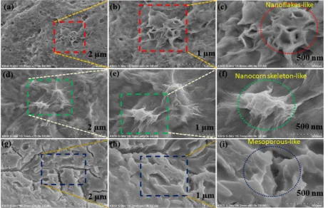
Fig 2. Shows the (a, b and c) SEM and FE-SEM images of CZ1h, (d, e and f) SEM and FE-SEM
images of CZ3h and SEM and (g, h and i) FE-SEM images of CZ7h nanostructures.
CZ was synthesized using the CBD method for various reaction times at 1h, 3h, and 7h on
Ni foam, such as CZ1h, CZ3h and CZ7h. Fig. 2a-i shows low and high magnification FE-SEM
images of the as-prepared samples. Fig. 2a-c presents the CZ1h synthesized electrode on Ni foam.
From Fig. 2a,b High magnification images of the active electrode revealed a nano-flake like
structure that was formed by irregular connections with a low surface area and many pore sizes.
In particular, Fig. 2c indicates large pore sizes and less adhesion, making it difficult for ions or
electrons to transport within the electrode. Fig. 2d-f presents the CZ3h synthesized electrode
indicating a well-interconnected hierarchical corn skeleton structure with a high surface area
comprised of CO nanorods covered uniformly with the ZO nanocorn skeleton-like surface area
Fig. 2d-e. The image in Fig. 2f shows uniformly interconnected and a large number of
nanoparticles, and significantly smaller pore sizes with strong adhesion to the active electrode,
which enhances the surface area of the material. These are useful for electrolyte access and electron
transport during the redox reaction. Fig. 2g-i shows the effects of increasing the time on the CZ7h
electrode. As the annealing time was extended from 3h to 7h, the similar mesoporous structure of
CZ7h was converted completely to disturbed nanoparticles with a weakened structure and large
pores, indicating interrupted adjacent pores and a reduced surface area of the active electrode, as
shown in Fig. 2g,h. Fig. 2i shows that the nanostructure is dispersed unevenly with voids among
the particles on the surface of the active electrode. This resulted in weak faradic reactivity between
the aqueous electrolyte and active electrode.
The morphological features and structural information of the as-obtained samples of CO,
ZO, and CZ1h, CZ3h and CZ7h were characterized by transmission electron microscopy (TEM
and HR-TEM), as shown in Fig. S2a-f in the Supporting information. Fig. S2a-c in the Supporting
information shows a TEM image of the CO electrode, which exhibits small sized nanorods and
nanoparticle-like morphology. As shown in Fig. S2a,b in the Supporting information, irregular CO
nanoparticles were formed, resulting in a low surface area. Fig. S2c in the supporting information
shows thin CO nanorods. Fig. S2d-f in the supporting information presents low and high
magnification TEM images of ZO nano-corn with good crystallinity with the observations from
the SEM images. The low magnification TEM images of ZO clearly showed the nanocorn skeleton
nature by the nanosheet-like morphology with curling folded edges and obvious features, as shown
block spots, indicating that the pores were interconnected completely with the nanocorn skeleton
surface, as shown in Fig. S2f in the Supporting information.
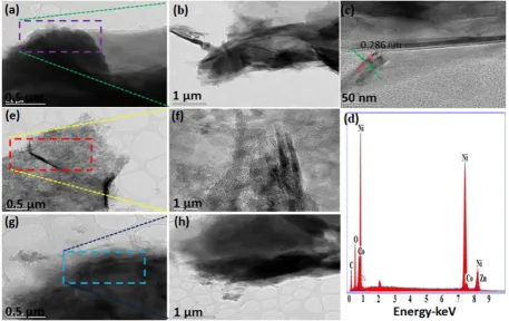
Fig 3. Shows the TEM and HR-TEM images for CZ3h, 1H and CZ7h composites. As shown in
Figure 3a-c presents a low and high magnifications TEM images of CZ3h composite electrode and
(d) EDS spectrum, (e,f) CZ1h composite electrode and (g,h) CZ7h composite electrode.
Fig. 3a presents low magnification images of the active electrode nanosheet like structures.
The CO nanorods were evidently coated with ZO corn straw nanostructures and formed a clear
image, as shown in Fig. 3b,c, indicating this structure may shorten the ion diffusion length
markedly for electrochemical reaction. On the other hand, EDS was performed on the CZ3h sample,
as shown in Fig. 3d and active electrode composed of Co, Zn, Ni, and O elements with no other
impurities being obtained. Fig. 3e,f present different magnification images of the CZ1h electrode.
nanoparticles on the edge of the ZO nanosheet was observed clearly in Fig. 3f. As shown in the
TEM images of CZ7h in Fig. 3g,h two different magnifications. Fig. 3g shows a thin nanosheet,
supporting the corresponding SEM images, which is also seen clearly in Fig. 2h.
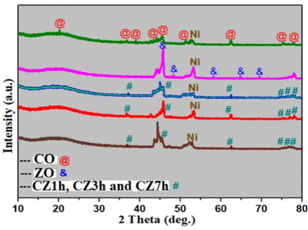
Fig 4. Shows the X-ray diffraction patterns (XRD) of all the samples.
The crystalline phase purity and composition of the as-prepared samples, CO, ZO, and
CZ1h, CZ3h, and CZ7h were examined by XRD as shown in Fig. 4. In the XRD pattern of CO,
the XRD peaks at 21.8, 36.84, 37.8, 43.3, 44.81, 49.7, 63.29, 75.2 and 78.40° 2θ were attributed
to the (101), (003), (311), (400), (113), (400), (200), (622), and (311) planes, respectively. In CO,
all the XRD peaks were indexed using (JCPDS No. 48-1719) and related to the cubic phase. On
the other hand, in the ZO sample, the XRD peaks at 47.72, 44.8, 56.95, 64.4, and 68.2° 2θ were
assigned to the (102), (400), (422), (220), and (112) planes of a well crystallized hexagonal
structure ZO (JCPDS No. 36-1451). In the remaining samples of CZ1h, CZ3h, and CZ7h, the XRD
(622) planes of cubic spinal (JCPDS No. 23-1390), respectively. Moreover, the XRD pattern in
Fig. 4 confirmed the successful preparation of CO and ZO on Ni foam. No other peaks for
impurities were observed, which confirms that the cobalt oxide precursor and zinc oxide precursor
had been transformed completely to the CZ composite after chemical bath deposition at 300 °C.
In addition to these peaks, one strong peak in all samples at 51.9° 2θ was assigned to Ni foam.
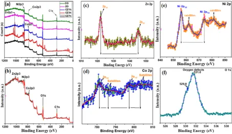
Fig 5. Shows the X-ray photoelectron spectroscopy (XPS) of (a) all samples and XPS spectra of
CZ3h of(b) survey spectrum, (c) Zn 2p, (d) Co2p, (e) Ni 2p and (f) O 1s.
XPS was also carried out to characterize the surface chemical composition and oxidation
states of the chemical bonding states of Co, Zn, Ni, and O on the surface of CO, ZO, and CZ1h,
CZ3h, and CZ7h, and the results are presented in Fig. 5. Fig. 5b shows the strong peaks for Zn 2p,
Co 2p, Ni 2p and O 1s in the CZ3h survey spectrum. The high resolution Zn 2p spectrum shows
the presence of divalent Zn, as shown in Fig. 5c [30]. The strong peaks for Co 2p were typically
deconvoluted into two peaks at 781.5 eV and 796.5 for Co 2p3/2 and Co 2p1/2, respectively, and
two weak shake-up satellite peaks at 786.2 eV and 802.6 eV, as shown in Fig. 5d [31,32]. The
energy gap between the main peaks was approximately 15 eV, suggesting the presence of Co2+
and Co3+. An energy gap between and main peaks and satellite peaks of around 6 eV would indicate
divalent Co. Fig. 5e shows the strong resolution XP spectrum of Ni 2p, which is typically separated
into two strong peaks at 857.0 eV and 875.0 eV for Ni 2p3/2 and Ni 2p1/2, respectively, and its
satellite peaks appear at 861.7 eV and 880.0 eV [33]. In addition to those in Fig. 5f shows the O
1s spectrum showed two deconvoluted peaks at 531.0 eV and 529.8 eV, suggesting hydroxide ions
and metal oxygen bonds in the sample [34,35].
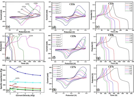
rate of 50 mV s-1. (b) Comparative GCD curves of the CO, ZO, CZ1h, CZ3h and CZ7h electrodes
at a current density of 3 A/g, (c) Specific capacitance vs. current density curve of as prepared
electrodes, (d,e) CV curves and GCD curves of the CZ1h electrodes at various scan rates and
current densities. (f,g) CV curves and GCD curves of the CZ3h electrodes at various scan rates
and current densities. (h,i) CV curves and GCD curves of the CZ7h electrodes at various scan rates
and current densities.
To examine the electrochemical behavior and supercapacitor properties of the as-prepared
CO, ZO, and composites, the CZ1h, CZ3h, and CZ7h synthesized electrodes were first investigated
in a three electrode system (Fig. 6). Fig. 6a compares the CV curves of all the CO, ZO, CZ1h,
CZ3h, and CZ7h electrodes in a 3 M KOH solution at a scan rate of 50 mV s-1 within a potential
window of 0.0 to 0.4 V. The electrochemical performance of the CZ3h electrode was significantly
higher than the remaining electrodes: CO, ZO, CZ1h, and CZ7h electrodes. The nanostructure of
CZ3h composite materials shows great adhesion on nickel foam substrate and surface area which
can provide more active sites for faradaic redox reactions and electron transport pathways,
resulting in greatly enhanced electrochemical performance. Fig. 6b shows the galvanostatic charge
discharge curves of all electrodes over 0.0 to 0.4 V and at 3 A/g. The prepared electrodes
underwent the faradic redox reversible reactions. Remarkably, the CZ3h electrode exhibited a high
specific capacitance, which is much larger than those for CO, ZO, CZ1h, and CZ7h electrodes.
These hierarchical corn skeleton structure of CZ3h nanocomposite was synthesized via a facile
chemical bath deposition method without binders and it offers many remarkable advantages such
as efficient electrical contact between nickel foam substrate and electroactive materials, simplified
electrode preparation, easy diffusion of the electrolyte and short ion diffusion pathways, thus
as-prepared samples calculated from the GCD curves at different current densities. For comparison,
the specific capacitance of the CZ3h electrode exhibited 1136 F/g at 3 A/g, which is higher than
those electrodes. The strong synergistic effect of CZ3h composite may contribute to the
remarkable superior electrical performances compared with other electrodes such as CO, ZO,
CZ1h and CZ7h. Fig. 6d shows the CV profile of the individual of CZ1h electrode. The shape of
the CV curve remained the same even at a low scan rate of 2 mV s-1 up to a high scan rate of 100
mV s-1 and that the GCD curves also maintained the same shape from current densities of 3 A/g to
7 A/g and exhibited a specific capacitance value of 240, 228, 214, 197 and 190 F/g as shown in
Fig. 6e. The CV curves of the CZ3h composite electrode were investigated from 2-100 mV s-1 (Fig.
6f). The CZ3h electrode showed a nano-corn morphology with an interconnected surface area,
which are favorable for easy transportation in the electrochemical reaction. On the other hand, the
GCD curves of the CZ3h electrode at various current densities ranged from current densities of 3
A/g to 7 A/g and exhibited a specific capacitance value of 1137, 1085, 892, 770 and 675 F/g are
shown in Fig. 6g. Construction of corn-skeleton structures with the combination of two different
materials has been proved as a promising strategy to boost the superior electrochemical
performance of metal oxides. Fig. 6h shows the CV curves of CZ7h electrode at various scan rates.
The current density increased with increasing scan rate, and all curves showed a unique shape and
the GCD curves also maintained the same shape from current densities value of 3 A/g to 7 A/g and
exhibited a specific capacitance value of 537, 512, 502, 492 and 475 F/g were shown in Fig. 6i.
Fig. S3a in the Supporting information presents the CV profile of the CO electrode, indicating the
clear shape of the CV curve from 2-100 mV s-1 and GCD curves also maintained the same shape
from current densities of 3 A/g to 7 A/g and exhibited a specific capacitance value of 274, 255,
information shows the CV curves of the ZO electrode recorded at scan rates of 2-100 mV s-1 within
the potential range from 0.0 to 0.4 V. The shape of the CV curve was the same even at a high scan
rate of 100 mV s-1. Fig. S3d in the Supporting information shows the charge/discharge curves at
current densities ranging from current densities of 3 A/g to 7 A/g and exhibited a specific
capacitance value of 383, 359, 312, 281 and 273 F/g, respectively.
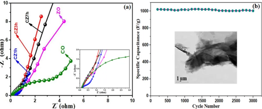
Fig 7. (a) EIS plots of the CO, ZO, CZ1h, CZ3h and CZ7h electrodes and (b) Cycling performance
of the CZ3h electrode at 4 A/g for 3000 cycles.
The ion diffusion and electron transfer in the electrode materials were examined. Figure
7a presents the Nyquist plot of all the electrodes over the frequency range of 0.100 Hz to 100 KHz.
Fig. 7a shows that the CZ3h electrode had a small semicircle in the high frequency range and a
more vertical line in the low frequency range than the CO, ZO, CZ1h, and CZ7h electrodes,
suggesting higher charge transfer between the active electrodes and electrolyte. These very small
circles are associated with rapid ion diffusion in the CZ3h electrode. These results show that
combinations of the KOH aqueous electrolyte and the intrinsic resistance of the active electrode
A long-term cycle test was performed to examine the stability, which is an indispensable factor
when determining the practical applicability of the CZ3h electrode, as shown in Fig. 7b. The
cycling stability of the CZ3h electrode was measured up to 3000 cycles by recording the GCD at
a current density of 4 A/g in a three electrode system. Figure 7b shows that the CZ3h electrode
exhibits excellent capacitance that still retained 98.3% of the initial value after 3000 cycles. This
was attributed to the gradual penetration of the electrolyte into the interior of the electrode
materials during cycling and the high structural stability of the electrode. Efficient electrical
contact between nickel foam substrate and electroactive materials, simplified electrode preparation,
easy diffusion of the electrolyte and short ion diffusion pathways, thus leasing to improve cycling
stability and rate capability.
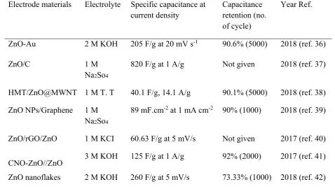
Table 1.
Comparison of capacitances between the present
CoO@ZnOelectrode and
similar Zn-Co-O based electrodes taken from the recently published reports.
Electrode materials Electrolyte Specific capacitance at current density
Capacitance retention (no. of cycle)
Year Ref.
ZnO-Au 2 M KOH 205 F/g at 20 mV s-1 90.6% (5000) 2018 (ref. 36)
ZnO/C 1 M
Na2So4
820 F/g at 1 A/g Not given 2018 (ref. 37)
HMT/ZnO@MWNT 1 M T. T 40.1 F/g, 14.1 A/g 90.1% (5000) 2018 (ref. 38)
ZnO NPs/Graphene 1 M Na2So4
89 mF.cm-2 at 1 mA cm-2 90% (1000) 2018 (ref. 39)
ZnO/rGO/ZnO 1 M KCI 60.63 F/g at 5 mV/s Not given 2017 (ref. 40)
CNO-ZnO//ZnO 3 M KOH 125 F/g at 1 A/g 92% (2000) 2017 (ref. 41)
Go/ZnO 1 M Na2So4
97 F/g at 0.5 A/g 90.8% (5000) 2018 (ref. 43)
C/CoO 2 M KOH 1052 F/g at 0.5 A/g 61% (10000) 2018 (ref. 44)
C@NiCo2O4 6 M KOH 404 F/g at 1 A/g 87.1% (1000) 2018 (ref. 45)
CuCoO-H 3 M KOH 405.6 F/g at 20 A/g 99.4% (10000) 2018 (ref. 46)
CoO@ZnO 2 M KOH 1136 F/g at 3 A/g cm-2 98.3% (3000) This work
Conclusion
CO, ZO and synthesized CZ1h, CZ3h and CZ7h nanostructures were synthesized on Ni
foam by an inexpensive and eco-friendly CBD method. Ni foam provides a higher surface area,
excellent electrical conductivity, very high porosity, and sufficient functional groups to the
material to enhance the electrochemical performance. Various electrochemical techniques were
carried out to characterize the nanostructures, morphology, and structural properties of the working
electrodes. The hierarchical interconnected corn skeleton of the CZ3h electrode could allow the
electrolyte to penetrate directly, indicating a reduction of the ionic transfer resistance thereby
improving the working material surface area efficiency and electron transport in electrochemical
mechanism. In a three-electrode system, the CZ3h active electrode exhibited a good specific
capacitance 1136 F/g at a current density of 3 A/g. In contrast, the remaining electrodes, CO, ZO,
CZ1h, and CZ7h, exhibited 274, 383, 240 and 537 F/g at a current density of 3 A/g in the
three-electrode system. Considering the encouraging electrochemical properties of the active three-electrodes
device, it is strongly believed that hierarchical corn skeleton nanostructures will form part of new
Author Contributions:
Conceptualization, A.K.Y.; Formal analysis, H.J.K.; Investigation,A.K.Y. and H.J.K.; Methodology, A.K.Y.; Supervision, A.K.Y.; Writing–original draft, A.K.Y.;
Writing–review & editing, A.K.Y. and H.J.K.
Funding
: This research was supported by the Basic Research Laboratory through the NationalResearch Foundations of Korea funded by the Ministry of Science, ICT and Future Planning
(NRF2015R1A4A1041584). In addition, this work was supported financially by BK 21 PLUS,
Creative Human Resource Development Program for IT Convergence, Pusan National University,
Busan, South Korea. Finally, special thanks are due to the KBSI for the instrumental
characterization.
Conflicts of interest:
The authors declare no conflict of interest.References
1 J. Cu, S. Liu and Y. Liu, RSC Adv., 2016, 6, 52137.
2 D. Cai, H. Huang, D. Wang, B. Liu, L. Wang, Y. Liu and Q. Li, ACS Appl. Mater. Mater.
Interfaces, 2014, 6, 15905-15912.
3 F. Gobal, M. Faraji, Appl. Phys. A, 2014,117, 2087-20194.
4 Y. A. Kumar, S. S. Rao, D. Punnose, C. V. Tulasivarma, C. V. V. V. Gopi, K. Prabakar and
H. J. Kim, R. Soc. open sci, 2017,4, 170427.
5 Y. Zhang, M. Ma, J. Yang, H. Su, W. Huang and X. Dong, Nanoscale, 2014, 6, 4303-4308.
6 Z. Chen, Z. Wan, T. Yang, M. Zhao, X. Lv, H. Wang, X. Ren & X. Mei, SCIENTIFIC
REPORTS, 2014, 6, 25151.
7 X. Meng, H. Sun, J. Zhu, H. Bi, Q. Han, X. Liu and X. Wang, New J. Chem., 2016, 40,
8 S. G. Kandalkar, J.L. Gunjakar, C.D. Lokhande, Applied Surface Science, 2008, 254,
5540-5544.
9 S. Liu, C. Mao, Y. Niu, F. Yi, J. Hou, S. Lu, J. Jiang, M. Xu, and C. Li, ACS Appl. Mater.
Interfaces, 2015, 7, 25568-25573.
10 Y. A. Kumar, S. S. Rao, D. Punnose, C. V. Tulasivarma, C. V. V. V. Gopi, K. Prabakar and
H. J. Kim, R. Soc. open sci, 2017,4, 170427.
11 K. J. Huang, J. Z. Zhang, G. W. Shi and Y. M. Liu, Materials Letters, 2014, 131, 45-48.
12 J. Y. Lin and S. W. Chou, RSC Adv., 2013, 3, 2043-2048.
13 J. Cheng, Y. Lu, K. Qiu, H. Yan, J. Xu, L. Han, X. Liu, J. Luo, J. K. Kim and Y. Luo,
SCIENTIFIC REPORTS, 2015, 5, 12099.
14 Y. A. Kumar, S. S. Rao, D. Punnose, C. V. Tulasivarma, C. V. V. V. Gopi, K. Prabakar and
H. J. Kim, R. Soc. open sci, 2017,4, 170427.
15 W. Dong, X. Wang, B. Li, L. Wang, B. Chen, C. Li, X. Li, T. Zhang and Z. Shi, Dalton Trans.,
2011, 40, 243-248.
16 R. Liu, L. Ma, S. Huang, J. Mei, E. Li and G. Yuan, J. Phys. Chem. C, 2016, 120,
28480-28488.
17 F. Tao, Y. Q. Zhao, G. Q. Zhang and H. L. Li, Electrochemistry Communications, 2007, 9,
1282-1287.
18 Z. Li, J. Han, L. Fan and R. Guo, 1952, CrystEngComm, 2015, 17, 1952-1958.
19 X. Wang, S. X. Zhao, L. Dong, Q. L. Lu, J. Zhu and C. W. Nan, Energy Storage Materials,
2017, 6, 180-187.
20 Y. A. Kumar, S. S. Rao, D. Punnose, C. V. Tulasivarma, C. V. V. V. Gopi, K. Prabakar and
21 J. Bai, K. Wang, J. Feng and S. Xiong, ACS Appl. Mater. Interfaces, 2015, 7, 22848-22857.
22 B. Balamuralitharan, S. N. Karthick, S. K. Balasingam, K. V. Hemalatha, S. Selvam, J. A.
Raj, K. Prabakar, Y. Jun and H. J. Kim, Energy Technol, 2017, 5, 1953-1962.
23 A. K. Singh, D. Sarkar, K. Karmakar, K. Mandal and G. G. Khan, ACS Appl. Mater.
Interfaces, 2016, 8, 20786-20786.
24 Y. A. Kumar, S. S. Rao, D. Punnose, C. V. Tulasivarma, C. V. V. V. Gopi, K. Prabakar and
H. J. Kim, R. Soc. open sci, 2017,4, 170427.
25 J. Jiang, W. Shi, S. Song, Q. Hao, W. Fan, X. Xia, X. Zhang, Q. Wang, C. Liu and D. Yan,
Journal of Power Sources, 2014, 248, 1281-1289.
26 S. Selvam, B. Balamuralitharan, S. Jegatheeswaran, M. Y. Kim, S. N. Karthick, J. A. Raj, P.
Boomi, M. Sundrarajan, K. Prabakar and H. J. Kim, J. Mater. Chem. A, 2017, 5, 1380-1386.
27 L. Liu, C. Zhao, H. Zhao, Q. Zhang, Y. Li, Electrochimica Acta, 2014, 135, 224-231.
28 L. Shen, L. Yu, X. Y. Yu, X. Zhang and X. W. (David) Lou, Angew, Chem. Int. Ed, 2015, 54,
1868-1872.
29 D. Cai, H. Huang, D. Wang, B. Liu, L. Wang, Y. Liu, Q. Li and T. Wang, ACS Appl.
Interfaces, 2014, 6, 15905-15912.
30 Y. Zhu, X. Ji, R. Yin, Z. Hu, X. Qiu, Z. Wu and Y. Liu, RSC Adv., 2017, 7, 11123-11123.
31 J. Du, G. Zhou, H. Zhang, C. Cheng, J. Ma, W. Wei, L. chen and T. Wang, ACS Appl. Mater.
Interfaces, 2013, 5, 7405-7409.
32 H. Niu, D. Zhou, X. Yang, X. Li, Q. Wang and F. Qu, J. Mater. Chem. A, 2015, 3,
18413-18421.
33 R. B. Pujari, A. C. Lokhande, J. H. Kim and C. D. Lokhande, RSC Adv., 2016, 6, 40593-40601.
35 Zheng, A. Kvit, Z. Cai and Z. Ma, J. Mater. Chem. A, 2017, 5, 12528-12541.
36 H. Mahajan, J. Bae and K. Yun, Journal of Alloys and Compounds, 2018, 758, 131.
37 C. Sasirekha, S. Arumugam and G. Muralidharan, Applied Surface Science, 2018, (Not yet
come and in Press full).
38 K. S. Lee, M. J. Shin, C. W. Park and J. D. Kim, Colloids and Surfaces Area, 2018, 538,
23-27.
39 E. Samuel, P. U. Londhe, B. Joshi, M. W. Kim, K. Kim, M. T. Swihart, N. B. Chaure and S.
S. Yoon, Journal of Alloys and Compounds, 2018, 741, 781-791.
40 M. Ghorbani, M. R. Golobostanfard and H. Abdizadeh, Applied Surface Science, 2017, 419,
277-285.
41 D. Mohapatra, S. Parida, S. Badrayyana and B. K. Singh, Applied Materials Today, 2017, 7,
212-221.
42 B. Pant, M. Park, G. P. Ojha, J. Park, Y. S. K and E. J. Lee, Journal of Colloid and Interface
Science, 2018, 522, 40-47.
43 K. S. Lee, C. W. Park, S. J. Lee and J. D. Kim, Journal of Alloys and Compounds, 2018, 739,
522-528.
44 J. Y. Long, Z. S. Yan, Y. Gong and J. H. Lin, Applied Surface Science, 2018, 448, 50-63.
45 W. Li, F. Yang, Z. Hu and Y. Liu, Journal of Alloys and Compounds., 2018, 749, 305-312.
46 C. Jin, Y. Cui, G. Zhang, W. Luo, Y. Liu, Y. Sun, Z. Tian and W. Zheng, Chemical Engineering