Link/Node Failure Recovery through Backup Path
Lengths
Ravula Prathap Kumar, Banothu Balaji, Dasari Yakobu, N Sai Bala Kishore
Department of Computer Science and Engineering, Vignan University, Guntur, AndhraPradesh, India
Abstract- the Internet has evolved into a platform with applications having strict demands on robustness and availability, like trading systems, online games, telephony, and video conferencing. This project develops novel mechanisms for recovering from failures in wired networks with proactive backup path calculations. The primary scheme provides resilience for up to two link failures along a path. A network should be minimum three edge connected in order to tolerate dual link failure. Protection graphs mechanism is required in order to handle the link/node failure. When failure occurs packets are routed over the protection graph. Then the network recovers from the first failure by tunneling the packet to the next-hop node. An extension to the basic scheme provides recovery from single-node failures in the network. It involves an identification of the failed node in the packet path and then routing the packet to the destination along an alternate path that does not containing the failed node. An efficient approach to route packets along link- or node disjoint paths in networks with minimum lookup time is to employ colored trees (CTs). In this approach, two trees, namely red and blue, are constructed rooted at a destination such that the paths from any node to the destination on the two trees are link- or node-disjoint. The effectiveness of these techniques was evaluated by simulating the developed algorithm over Arpanet network topology.
Keywords- IP fast reroute, failure recovery, multiple link failures, node failure, network protection, independent trees.
1. INTRODUCTION
The Internet has evolved into a platform with applications having strict demands on robustness and availability, like trading systems, online games, telephony, and video conferencing. For these applications, even short service disruptions caused by routing convergence can lead to intolerable performance degradations. As a response, several mechanisms have been proposed to give fast recovery from failures at the Internet Protocol (IP) layer. In these schemes, backup next-hops are prepared before a failure occurs, and the discovering router handles a component failure locally without signaling to the rest of the network.
Using one of these fast-rerouting methods, the recovery time is mainly decided by the time it takes to discover the failure. This can typically be done in a few milliseconds, using signaling from the physical layer or a failure detection protocol like BFD. This is a significant improvement over the recovery times achieved by a normal routing re-convergence, which typically takes several seconds. Recovery times can be reduced by aggressive timer settings, but this comes at the risk of triggering unwanted routing convergence due to, e.g., flapping links.
Often, proactive recovery schemes are thought of as a first line of defense against component failures. They are used to maintain valid routing paths between the nodes in the network, until the routing protocol converges on a new global view of the topology. Such a strategy is particularly germane when facing transient failures, which are common in IP networks today.
While single-link failures are the most common failure type, it is also interesting to explore methods that protect against two simultaneous link failures. Measurement studies indicate that about 30% of unplanned failures affect more than one link. Half of these affect links that are not connected to the same node. It is sometimes possible to identify Shared Risk Link Groups (SRLG) of links that are likely to fail simultaneously by a careful mapping of components that share the same underlying fiber infrastructure. This might, however, be a complex and difficult task since the dependencies in the underlying transport network might not be fully known and can change over time.
2. RELATED WORK
S. Kini, S. Ramasubramanian, A. Kvalbein, and A. Hansen [1] developed a novel mechanism for recovering from dual link failures in IP networks. The proposed technique requires three protection addresses for every node in addition to the normal address associated with every protection address of a node in a protection graph. Each link connected to the node is removed in at least one of protection graphs and every protection graph is guaranteed to be two-edge connected. The network recovers from the first failure by tunneling the packet to the next-hop node using one of the protection addresses of the next-hop node; and the packet is routed over the protection graph corresponding to that protection address.
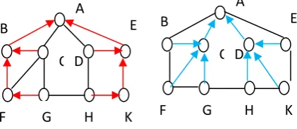
(a) Red Tree rooted at A (b) Blue Tree rooted at A
Fig. 2.1 Example Network with colsored trees rooted at node A
S. Lee, Y. Yu, S. Nelakuditi, Z.-L. Zhang, and C.-N. Chuah [4] proposes a novel proactive intra-domain routing approach – Failure Insensitive Routing (FIR) – for ensuring high service availability and reliability without changing the conventional destination-based forwarding paradigm. There are two key ideas that under the proposed approach: interface-specific forwarding and local rerouting. These ideas enable us to infer link failures based on packets’ flight (the interfaces they are coming from), pre-compute interface-specific forwarding tables (“alternative” paths) in a distributed manner and trigger local rerouting without relying on network-wide link-state advertisements. The proposed approach can effectively handle transient link failures that are most frequent in today’s networks. It enhances failure resiliency and routing stability by suppressing the advertisement of transient failures and locally rerouting packets during the suppression period.
A.Kvalbein, A. F. Hansen, S. Gjessing, and O. Lysne [3] presented a new recovery scheme called Multiple Routing Configurations (MRC). MRC is based on keeping additional routing information in the routers, and allows packet forwarding to continue on an alternative output link immediately after the detection of a failure. The proposed scheme guarantees recovery in all single failure scenarios, using a single mechanism to handle both link and node failures, and without knowing the root cause of the failure. MRC is strictly connectionless, and assumes only destination based hop-by-hop forwarding. It can be implemented with only minor changes to existing solutions. In this paper present MRC, and analyze its performance
with respect to scalability, backup path lengths, and load distribution after a failure.
A.Markopoulou, G. Iannaccone, S. Bhattacharyya, C.-N. Chuah, and C. Diot [9], analyze IS-IS routing updates from Sprint’s IP network to characterize failures that affect IP connectivity. Failures are first classified based on probable causes such as maintenance activities, router-related and optical layer problems. Key temporal and spatial characteristics of each class are analyzed and, when appropriate, parameterized using well-known distributions. The results indicate that 20% of all failures are due to planned maintenance activities. The classification of failures according to different causes reveals the nature and extent of failures in today’s IP backbones.
3. THEORETICAL ANALYSIS 3.1.Project Scope
The scope of this project is that develops novel mechanisms for recovering from failures in IP networks with proactive backup path calculations and tunneling. The primary scheme provides resilience for up to two link failures along a path. The highlight of the developed routing approach is that a node reroutes a packet around the failed link without the knowledge of the second link failure.
3.2. Existing System
The link-state routing protocols such as OSPF and ISIS, which are commonly deployed in today’s networks, react to link failures by having routers detect adjacent link failures, disseminate link state changes, and then recomputed their routing tables using the updated topology information. The resumption of forwarding after a link failure typically takes several seconds. During this period, some destinations could not be reached and the packets to those destinations would be dropped. In today’s high speed networks, even a short recovery time can cause huge packet losses.
Traditional routing in IP networks involves computing a forwarding link for each destination, referred to as the primary (preferred) forwarding link. When a packet is received at a node, it is forwarded along the primary forwarding link corresponding to the destination address in the packet. To recover from the failure of the forwarding link, a node must reroute the packet over a different link, referred to as the backup forwarding link. The backup forwarding link at different nodes in the network must be chosen in a consistent manner to avoid looping.
Equal cost multi-path (ECMP) [RFC 2991, RFC 2992] is a technique employed in IP networks today that computes multiple forwarding links for a specific destination as long as the cost of the paths through each forwarding link is the same as the shortest path cost to the destination.
Every packet, whether forwarded along the primary or backup forwarding link, will be forwarded to a node with a lower cost to the destination than the current node. This monotonic property of the multiple paths keeps the routing algorithm simple, where a packet need not be identified whether it was a re-routed packet or not. In addition, the failure of a link need not be advertised in the network. However, the drawback of the ECMP approach is that not all nodes in the network may have equal cost multiple (shortest) paths to a destination. A trivial example is a ring
C D
A
E
K
H
F G
B
C D
E
K H G
F
B
network with odd number of nodes, where no node has ECMP paths to another node. In a ring network with even number of nodes, every node has two equal hop length paths to only one other node in the network.
Solutions to accelerate the convergence of link state routing protocols have been proposed. The general recipe calls for fine-tuning of several parameters associated with link failure detection, link state dissemination and routing table re-computation. Although these solutions can improve the convergence time of routing protocols, they also run the risk of introducing instability in the network, in particular in the face of frequent transient link failures.
Faster convergence requires earlier advertisements of many transient link failure events that may last only a few seconds; just as the new routing tables are computed, they need to be recomputed again due to new link state updates. On the other hand, suppression of a link failure notification by the adjacent node would increase forwarding discontinuity. Other nodes that are not aware of the failure continue to route packets to some destinations through the failed link which get dropped at the adjacent node.
Disadvantages:
If the primary forwarding link fails, a packet is routed over the auxiliary graph where the primary link was removed.
The drawback of MRC approach is that it does not bound the number of auxiliary graphs employed.
The auxiliary graphs are constructed such that for any combination of two component failures exist an auxiliary graph that does not use.
3.3.PROPOSED SYSTEM
The goal of this project is to enhance the robustness of the network to: 1) dual-link failures; and 2) single-node failures. To this end, this project develops techniques that combine the positive aspects of the various single-link and node failure recovery techniques.
The default (normal) address of a node is denoted by u0. This acts as the primary address for the routing protocol. In addition, there are three backup addresses denoted by u1, u2, and u3, which are employed whenever a link failure is encountered.
A network must be three-edge-connected in order to be resilient to two arbitrary link failures, irrespective of the recovery strategy employed. The links connected to node are divided into three protection groups, denoted by Lu1, Lu2 and Lu3. Node is associated with three protection (auxiliary) graphs. The decomposition of the graph into three protection graphs for every node u is achieved by temporarily removing node and obtaining the connected components in the resultant network. If the network is two-vertex-connected, then removal of any one node will keep the remaining network connected. However, if the network is only one-vertex-connected, removal of node may split the network into multiple connected components.
By default, all packets are forwarded toward the destination prefix decided by the destination address in the packet header. Traffic is routed on graph G toward the selected egress node. A packet destined to is transmitted with address d0, and is routed on graph G. The network is assumed to employ any desired routing algorithm under no
failure scenario. Every node is assumed to route the packet based on the destination address and the interface (incoming link) over which the packet was received. For every destination–interface pair, the routing table at a node specifies the interface (outgoing link) over which the packet has to be forwarded. Note that if the network employs shortest path routing, the outgoing link for default destination address for a node would be the same, irrespective of the incoming interface.
The packet is now routed on the protection graph Gyg, where it may encounter at most one additional link failure. Given that the protection graph Gyg is two-edge-connected, this employs the colored tree technique to route the packet. Under the colored tree approach, in every protection graph Gyg, and construct two trees, namely red and blue, rooted at such that the path from every node to is link-disjoint. Observe that an incoming link in the protection graph may either be red or blue. Therefore, the tree on which a packet is routed is identified based on the incoming link. Once the packet reaches the desired node, the top header is removed, and the packet continues on its original path in G.
There are two approaches to select the default tree over which the packet is routed. The first approach is referred to as the red tree first (RTF), where every packet is forwarded along the red tree. Upon failure of a red forwarding link in the protection graph, the packet will be forwarded along the blue tree. When a blue forwarding link fails, the packet is simply dropped as it indicates that the packet has already experienced two link failures. Note that if the RTF approach is employed, and may construct the red and blue trees such that the path on the red tree is minimized.
The second approach is referred to as the shortest tree first (STF), where a packet is forwarded along the tree that provides the shortest path to the root of the tree. As the packets are first forwarded on the shortest tree, the packets experience lower delays under single-link failure scenarios. While the red tree may offer the shortest path for node in the protection graph, the blue tree may offer the shortest path for another node in the same protection graph. A packet that is forwarded on the red (blue) tree will be rerouted to the blue(red) tree upon a red (blue) forwarding link failure.
The limitation of this approach is that it may result in perennial looping if more than two links fail in the network. Unlike the RTF approach, where a packet to be forwarded on the blue link implies that it has already experienced two link failures, the STF approach does not provide any implicit indication on the number of failures experienced by the packet.
Advantages
The recovery mechanism of dual link or single node failure avoids the data leakage or data loss.
Algorithm: Input: Source Destination
Nodes involved in Single Link failure
Nodes involved in another single link failure (creates dual link failure)
Direct links One hop Links
Linkstatus (0: no failure; 1: failure) usedState( eachNode) = 0;
count = 0; // number of nexthop m1 = 1st_directlink
m2 = 2nd _directlink Create single link failure Call updateLinkStatus { }
Call protectionGraph {source destination} ProtectionGraph {source destination} { Check direct Links of source
i)if (any_directlink==destination &&(linkstatus(directlink)== 0))
nexthop = destination
a.if((linkstatus(m1)==0) &&(usedState(m1)== 0) b.increment count
c.nexthop(count) = m1
ii)if((linkstatus(m2)==0)&&(usedState(m2)==0) a.increment count
b.nexthop(count) = m2
iii)if((linkstatus(3rd _directlink) = = 0) && ( usedState(3rd _directlink) = = 0) )
a.increment count
b.nexthop(count) = 3rd _directlink
iv)if((linkstatus(1st _onehoplink) = = 0) && ( usedState(1st _ onehoplink) = = 0) )
a.increment count
b.nexthop(count) = intermediate Node of 1st onehop link c.increment count
d.nexthop(count) = 1st onehop link
v)if((linkstatus(2nd _onehoplink) = = 0) &&(usedState(2nd _ onehoplink) = = 0)
a.increment count
b.nexthop(count) = intermediate Node of 2nd onehop link c.increment count
d.nexthop(count) = 2nd onehop link
vi)if((linkstatus(3rd_onehoplink)==0)&&(usedState (3rd_ onehoplink)==0))
a.increment count
b.nexthop(count) = intermediate Node of 3rd onehop link c.increment count
d.nexthop(count) = 3rd onehop link
Call protectionGraph {source destination} if any of the above condition is satisfied by assigning current nexthop as current source
vii) if none of the above condition is satisfied assign the previous nexthop as current source and call
protectionGraph {source destination}
viii)Repeat the steps above till current nexthop becomes destination
ix)RedTree ( ) x)BlueTree ( ) xi)Tunneling ( ) }
RedTree () {
Assign current nexthop details Assign nexthop count as backup path length }
BlueTree () {
m1 = 2nd Direct Link
m2 = 1st Direct Link
Call ProtectionGraph {source destination} {} Assign current nexthop details Assign nexthop count as backup path length }
find shortest path by comparing path length of both trees Tunneling () {
if (RTF approach)
Tunneling via the calculated nexthop from source to destination
if (STF approach)
Tunneling via the calculated nexthop from source to destination over shortest path tree
}
Create Dual link failure Call updateLinkStatus { }
Call protectionGraph {source destination} Create Node failure
Call updateLinkStatus { }
Call protectionGraph {source destination}
4. SIMULATION SYSTEM DESIGN 4.1. Architectural Diagram
5.
5. RESULTS
As in the case of single-link, dual-link, single-node failure recovery analysis, this obtain a plot of the average modified path lengths and expected path lengths against the shortest path lengths for node failures.
5.1 Screen Shots
Software testing is an investigation conducted to provide stakeholders with information about the quality of the product or service under test. Software testing also provides an objective, independent view of the software to allow the business to appreciate and understand the risks of software implementation. Test techniques include, but are not
Packet
Forwarding
Node 2
Packet Forwarding
Failure Detection
Node 3
Failure Recovery
Packet Forwarding
Node 4
Node 1
Packet
limited to, the process of executing a program or application with the intent of finding software bugs.
5.1.1 Inserting input for Source and Destination and also for Single-link, Dual-link, and Single-node Failure
Fig 5.1.1 Input arguments
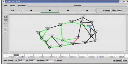
5.1.2 Creating a network is Arpanet with 20 nodes and 32 links
Inputs: Source: 9 Destination: 14
Fig 5.1.2 Arpanet
5.1.3 Single link failure: 7-9 At 0.5sce
Fig 5.1.3.1 Single link failure
Recovery from Single-link Failure under RTF and STF Approaches
Backup Path Length for RTF is 13 Next hop list for RTF is
8 6 4 2 0 1 3
5 7 8 19 16 14
Fig 5.1.3.2 RTF Approach under Single-Link Failure Backup Path Length for STF approach is 12
Next hop list for STF is
8 7 5 6 4 3 12
0 19 6 14
Fig 5.1.3.3 STF Approach under Single-Link Failure
5.1.4 Dual-Link Failure: 9-8 At 5.0sce
Fig 5.1.4.1 Dual link failure
Recovery from Dual-link Failure under RTF and STF Approaches
Backup Path Length for RTF is 3 Next hop list for RTF is
15 13 14
Fig 5.1.4.2 Dual link failure recovery in RTF Backup Path Length for STF is 3
Fig 5.1.4.3 Dual link failure recovery in STF
5.1.5 Single-Node Failure:13 At 9.0 sec
Fig 5.1.5 .1 Single-node failure
Recovery from Single-Node Failure under RTF and STF Approaches
Backup Path Length for RTF is 4 Next hop list for RTF is
15 17 16 14
Fig 5.1.5.2 Single-node failure recovery in rtf Backup Path Length for STF is 4
Next hop list for STF is
15 17 16 14
Fig 5.1.5.3 Single-node failure recovery in STF
5.1.6 Protection Graph
All packets are forwarded toward the destination prefix decided by the destination address in the packet header. Traffic is routed on graph G toward the selected egress node. A packet destined to is transmitted with address d0, and is routed on graph G.
Fig 7.1.6 protection graph
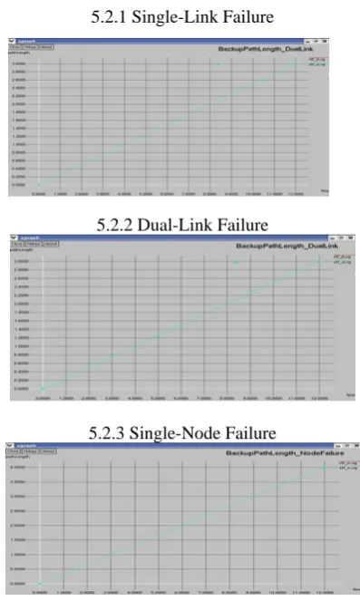
5.2 GRAPHS
Plotting Graphs for Link, Dual-Link, and Single-node Failure Recovery
Consider: x Time
YBackup path length
5.2.1 Single-Link Failure
5.2.2 Dual-Link Failure
5.2.3 Single-Node Failure
5.3 PERFORMANCE EVALUATION
Recovery from single-link, dual-link, single-node failures, the performance metrics that use for evaluation are: 1) average backup path length (recovery path); 2) maximum backup path length (recovery path) under single and dual link failures; 3) average shortest path length under single-node failure.
Where
METRIC ARPANET
RTF STF Average Backup Path
Length(Single-link failure) 12.2 11.1 Maximum Backup Path
Length(Single-link Failure) 13 12 Average Backup Path
Length(Dual-link failure) 11 9
Maximum Backup Path
Length(Dual-link Failure) 13 11
Table 5.3.1 Average and Maximum Backup Path Length under Single and Dual Link Failures Using RTF and STF Approaches
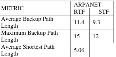
METRIC ARPANET
RTF STF Average Backup Path
Length 11.4 9.3
Maximum Backup Path
Length 15 12
Average Shortest Path
Length 5.06
Table 5.3.2 Average and Maximum Backup Path Length under Single Node Failure Using RTF and STF Approaches
6. CONCLUSION
This project develops two novel schemes to provide failure resilience in wired networks using tunneling. The first scheme handles up to two link failures. The first failure is handled by routing the packet in a protection graph, where each protection graph is designed to handle another link failure. This project develops the necessary theory to prove that the links connected to a node may be grouped such that at most three protection graphs are needed per node. The project uses aspects from established schemes as intermediate steps and does not impose restrictions on the routing protocol handling the normal failure-free scenario.
This project discusses two approaches, namely RTF and STF, to forward the tunneled packet in the protection graph, describing the benefit of shorter paths in STF at the cost of an extra overhead bit. The second scheme extends the first scheme so that it provides recovery from dual-link failures or a single-node failure. A node failure is assumed when three separate links connected to the same node are unavailable. The packet is then forwarded along a path to the destination avoiding the failed node. The performance of the schemes is evaluated by applying the algorithms to available failure paths and comparing the path lengths obtained with the two approaches. Through simulations, show that the average recovery path lengths are significantly reduced with the STF approach as compared to the RTF approach.
FUTURE WORK
The Enhancement of this project includes creation of more number of nodes and links, and also simulate recovery scheme for different types of wired networks in order to achieve better performance.
REFERENCES
[1] S. Kini, S. Ramasubramanian, A. Kvalbein, and A. Hansen, “Fast recovery from dual link failures in IP networks,” in Proc. IEEE INFOCOM, 2009, pp. 1368–1376.
[2] M. Shand, S. Bryant, and S. Previdi, “IP fast reroute using not-via addresses,” Internet Draft draft-ietf-rtgwg-ipfrr-notvia-addresses-05, Mar. 2010.
[3] A. Kvalbein, A. F. Hansen, S. Gjessing, and O. Lysne, “Fast IP network recovery using multiple routing configurations,” in Proc. IEEE INFOCOM, Apr. 2006.
[4] S. Lee, Y. Yu, S. Nelakuditi, Z.-L. Zhang, and C.-N. Chuah, “Proactive vs. reactive approaches to failure resilient routing,” in Proc. IEEE INFOCOM, Mar. 2004, vol. 1, pp. 176–186.
[5] S. Ramasubramanian, M. Harkara, and M. Krunz, “Linear time distributed construction of colored trees for disjoint multipath routing,” Comput. Netw. J., vol. 51, no. 10, pp. 2854–2866, Jul. 2007.
[6] G. Schollmeier, J. Charzinski, A. Kirstädter, C. Reichert, K. J. Schrodi, Y. Glickman, and C. Winkler, “Improving the resilience in IP networks,” in Proc. HPSR, Torino, Italy, Jun. 2003, pp. 91–96. [7] D. Ward and D. Katz, “Bidirectional forwarding detection,” Internet
Draft draft-ietf-bfd-base-11.txt, Jan. 2010, work in progress. [8] P. Francois, C. Filsfils, J. Evans, and O. Bonaventure, “Achieving
sub-second IGP convergence in large IP networks,” ACM SIGCOMM Comput. Commun. Rev., vol. 35, no. 2, pp. 35–44, Jul. 2005. [9] A. Markopoulou, G. Iannaccone, S. Bhattacharyya, C.-N. Chuah, and
C. Diot, “Characterization of failures in an IP backbone network,” in Proc. IEEE INFOCOM, Mar. 2004, vol. 4, pp. 2307–2317. [10] C. Perkins, “IP encapsulation within IP,” RFC 2003, Oct. 1996. [11]. NS Simulator for Beginners By Eitan Altman, Tania Jimenez. [12].An Introduction to Network Modeling and Simulation for the