001
THE SELECTION OF NON-MARINE MOLLUSCAN SHELLS FOR RADIOCARBON DATING
by
TIMOTHY JOHN STURGIS YATES Department of Geography, University College London.
A thesis submitted for the degree of Doctor of Philosophy
in the University of London.
dismissed entirely because the results are prone to distortion from post-depositional diagenesis, or the incorporation of material with a low &4C/12C ratio whilst the mollusc was alive, or both. The thesis attempts to discuss how the relative importance of the two factors can be assessed and the corresponding ages corrected accordingly.
Diagenesis was studied by comparing the structure and chemical composition of 39 species of British molluscs from modern specimens with those of fossil samples. Three main effects of diagenesis were studied using light and scanning electron microscopy, mass spectrometry and atomic absorption spectroscopy: the transformation of aragonite to calcite, a reduction in the standard deviation associated with the distribution of major ion concentrations within a shell population, and an enrichment in the lighter isotopes of carbon and oxygen. Only the transformation of mineralogy proved to be syfficiently sensitive to detect diagenetic material present at levels of 1-27.. The effects of diet and ambient carbon dioxide were studied by chemical analysis and mass spectrometry. Differences in stable isotope ratio values between micro-environments were found to be significantly greater than those between and within species. The established relationship between 13 C, I4 C and the environment can be used to identify shells in which the apparent age effect will be at a minimum.
Comparison of 14 C dates for charcoal and untreated shell samples showed that the above sources of error led to discrepancies of as much as 1500 years in the shell dates. Seven samples selected and pretreated in accordance with the procedures proposed in this thesis gave ages within two standard deviations of the values accepted for the deposit
003
TABLE OF CONTENTS
ABSTRACT 2
TABLE OF CONTENTS 3
LIST OF FIGURES 9
LIST OF TABLES 14
ACKNOWLEGDEMENT5 18
NOTES ON ISOTOPE CONVENTIONS 20
1. INTRODUCTION 21
1.1 SHELLS IN I4C DATING 21
1.2 SOURCES OF AGE ERROR IN I4 C DATES ON 22 NON-MARINE SHELLS
1.3 RADIOCARBON DATING OF SHELLS 23
1.31 Origins of Radiocarbon 23
1.32 Conventional Measurement of I4C Activity 24 1.33 Accelerator Mass Spectrometry (AMS) 26 1.4 STRUCTURE OF THE THESIS - AIMS AND METHODS 28
1.41 Aims of the Thesis 28
1.42 Methods and Approaches 28
1.43 Limiting Constraints Associated with the 30 Methods Applied
1.5 RADIOCARBON DATING OF NON-MARINE MOLLUSCAN SHELLS
- PREVIOUS STUDIES AND ANSWERS 31
2. ENVIRONMENT AND ECOLOGY 35
Environmental Indicators
2.22 Ecology of species in this study 39 2.3 ENVIRONMENT AND ECOLOGY OF MODERN SAMPLE SITES 43
2.31 Introduction 43
2.32 Oldlands Wood, Surrey 43
2.33 Hayle Iowans, Cornwall 51
2.34 Graffy, Co.Mayo, Eire 61
2.4 ENVIRONMENT AND ECOLOGY OF FOSSIL SITES 65
2.41 Introduction 65
2.42 Carrowmore, Co.Mayo, Eire 65
2.43 Newlands Cross, Dublin, Eire 68
2.44 Caerwys, Clwyd, Wales 71
2.45 Inchrory, Glen Avon, Banffshire 74
2.46 Castlethorpe, Lincolnshire 78
2.47 Binnel Point, Isle of Wight 81
2.48 Netanya, Israel 84
2.5 DIAGENETIC ENVIRONMENTS 86
2.6 EFFECT OF ECOLOGY AND ENVIRONMENT ON 14 C ACTIVITY 92
3. SHELL FORMATION AND GROWTH 96
3.1 THE FORMATION OF MOLLUSCAN SHELLS 96
3.11 Introduction 96
3.12 The Organic Components 97
3.13 The Inorganic Components 97
3.2 INPUT SOURCES FOR SHELL COMPONENTS 106 3.21 Introduction and Previous Studies 106 3.22 Estimates of the Relative Contributions of the
Different Sources of Shell Material 116
005
3.3 SHELL GROWTH AND MOLLUSCAN POPULATION 122 3.31 Age Structure and Radiocarbon Dating 122
3.4 BANDING POLYMORPHISM 127
4. THE STRUCTURE OF NON-MARINE MOLLUSCAN SHELLS 131
4.1 THE MINERALOGY OF SHELLS 131
4.2 THE BACKGROUND TO ULTRASTRUCTURAL ANALYSIS 134 4.3 THE STRUCTURE OF MOLLUSCAN SHELLS 136 4.31 The Nomenclature of Shells 136
4.32 Nacreous Structure 138
4.33 Foliated Structure 142
4.34 Prismatic Structure 143
4.35 Crossed-lamellar Structure 145 4.36 Complex Crossed-lamellar Structure 149
4.37 Homogeneous Structure 150
4.38 Myostracal Layers 151
4.4 THE STRUCTURE OF BRITISH FRESHWATER AND TERRESTRIAL 154 MOLLUSC SHELLS
4.41 The Structure of Freshwater Bivalves 154 4.42 The Structure of Freshwater Gastropods 159 4.43 The Structure of Terrestrial Gastropods 168
4.44 Conclusions 186
5. CHEMICAL AND ISOTOPIC COMPOSITION OF TERRESTRIAL SHELLS 190
5.1 GENERAL INTRODUCTION 190
5.2 METHODS OF ANALYSIS 190
5.21 Stable Isotopes 190
5.22 Atomic Absorption Spectrophotometry (AAS) 196 5.3 RESULTS OF STABLE ISOTOPE ANALYSES 199
5.33 Conclusions 259
5.4 RESULTS OF CHEMICAL ANALYSES 262
5.41 Modern Samples 262
5.42 Fossil Samples 271
5.5 THE RELATIONSHIP BETWEEN SHELL COMPOSITION AND
I4 C CONTENT 274
6. POST-DEPOSITIONAL CHANGES IN MOLLUSCAN SHELL STRUCTURE
AND CHEMISTRY 276
6.1 INTRODUCTION 276
6.2 POST-DEPOSITIONAL CHANGES IN MINERALOGY AND STRUCTURE 276
6.21 Introduction 276
6.22 The Mechanisms of Diagenetic Change 277 6.23 Structures of Diagenetic Change 284
6.24 Conclusions 294
6.3 STRUCTURAL CHANGES OBSERVED IN THE SHELLS OF 294 TERRESTRIAL MOLLUSCS
6.31 Introduction 294
6.32 Etching 297
6.33 Surface Crusts 297
6.34 The Replacement of Aragonite by Calcite 300 6.35 Dissolution of Shell Material and Cementation
of Sediments 305
6.4 THEORETICAL LIMITS OF DETECTION FOR CONTAMINATION
AND DIAGENETICALLY ALTERED MATERIAL 307 6.5 POST-DEPOSITIONAL ALTERATION OF THE CHEMICAL AND
ISOTOPIC COMPOSITION OF SHELLS 312
6.6 IMPLICATIONS OF STRUCTURAL, CHEMICAL AND ISOTOPIC
007
6.61 Effect of Structural and Mineralogical Changes 322
6.62 Effect of Chemical and Isotopic Exchange 322
7. METHODS OF DETECTION OF STRUCTURAL CHANGES IN SHELLS 327
7.1 INTRODUCTION 327
7.2 LOW-POWERED BINOCULAR MICROSCOPY 327
7.21 Matrix 328
7.22 Shell 328
7.3 ACETATE FILM PEELS 329
7.31 Introduction 329
7.32 Method 330
7.33 Conclusions 334
7.4 SCANNING ELECTRON MICROSCOPY 335
7.41 Introduction 335
7.42 Preparation of Stubs 336
7.43 Equipment 338
7.44 Stereo-pair Photographs 339
7.45 Energy Dispersive X-ray Analysis (EDAX) 339
7.46 Backscattered Electron Images 342
7.47 The Limits of Scanning Electron Microscopy 343
7.5 X-RAY DIFFRACTION ANALYSIS 343
7.51 Introduction 343
7.52 Theory of X-ray Diffraction Analysis 344
7.53 Sample Preparation 346
7.54 Analysis 347
7.55 Calibration and Reproducibility 348
7.56 Limitations of the Method 348
8. SELECTION AND VALIDATION OF SAMPLES 352
8.1 INTRODUCTION 352
8.22 Cleaning and Pretreatment 356
8.3 AMINO-ACID RACEMIZATION 361
8.31 Introduction 361
8.32 Method 361
8.33 Results 362
8.4 FIRST-ORDER 14 C DATING 363
8.5 VALIDATION OF THE SELECTION PROCEDURES 364
8.51 Introduction 364
8.52 Details of the Samples 365
8.53 Discussion of the Results 365
8.6 CONCLUSIONS 389
9. CONCLUSIONS 391
9.1 THE QUESTION 391
9.2 GENERAL CONCLUSIONS 391
9.3 SPECIFIC CONCLUSIONS 391
9.31 Type of Context and Availability of Samples 392
9.32 The Availability of CaCO 3 Sources and their
14 C Content 393
9.33 Ecology and Habits of Snail Species 394
9.34 Isotopic and Chemical Composition of Shells 394
9.35 Post-depositional Structural and 396
Chemical Changes
9.36 Availability of Time and Equipment 397
9.37 Validation 397
9.4 FUTURE WORK 398
009
LIST OF FIGURES Figure 1.1 Principles of AMS 14 C dating.
2.1 Stages in the formation of a subfossil landsnail assemblage.
2.2 Location of modern and fossil sample sites in the British Isles.
2.3 Location of modern sample sites at Oldlands Wood, Surrey. 2.4 Location of modern sample sites at Hayle Iowans.
2.5 Location of modern sample site at Graffy and fossil sample site at Carrowmore, Co.Mayo, Eire.
2.6 The stratigraphy and molluscan fauna from Carrrowmore Site B, Co.Mayo.
2.7 The stratigraphy and molluscan fauna from Newlands Cross, Dublin.
2.8 A quarry section at Caerwys, Clwyd.
2.9 The stratigraphy and molluscan fauna from Inchrory, Banffshire.
2.10 The stratigraphy and molluscan fauna from Castlethorpe Site 3, Lincolnshire.
2.11 The stratigraphy and molluscan fauna at Binnel Point, Isle of Wight.
2.12 Sources of calcium carbonate available for redeposition. 2.13 Basic diagenetic environments (Zones 1-4).
3.1 Diagram of the relationship between shell and mantle in a freshwater clam.
3.2 Diagram of compartments in molluscs.
3.5 Pathways for the incorporation of carbonate and CO2 in water.
4.1 The structure of calcite
4.2 External features and structrues of a freshwater bivalve. 4.3 External features and structures of a terrestrial
gastropod.
4.4 Crossed-lamellar structure in a shell of Theodoxus fluviatilis.
4.5 Nacreous structure in a shell of Unio species.
4.6 Breaks in growth in a shell of Theodoxus fluviatilis. 4.7 Pitting and fine crystals in a shell of Theodoxus
fluviatilis.
4.8 Pseudo-prismatic crystals in a shell of Theodoxus fluviatilis.
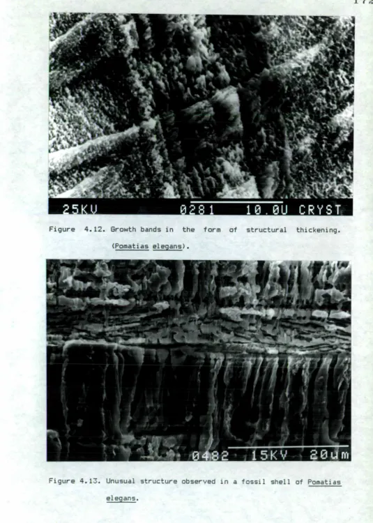
4.9 Crossed-lamellar structure of Viviparus viviparus. 4.10 Crossed-lamellar structure of Lymnaea peregra. 4.11 Crossed-lamellar structure of Pomatias elegans. 4.12 Growth bands in the form of structural thickening
(Pomatias elegans).
4.13 Unusual structure observed in a fossil shell of Pomatias elegans.
4.14 Detail of figure 4.13.
4.15 Crossed-lamellar structure of Retinella nitidula.
4.16 Four layers of crossed-lamellar structure in a shell of Arianta arbustorum.
4.17 Comparison of the structures of shells of Helix pomatia. 4.18 Sketch diagram of the structure of a shell of
011
4.19 Composite diagram of a cross-section of a shell of Helix pomatia.
4.20 Third-order lamellae in a shell of Helix pomatia.
4.21 Detail of the crossed-lamellar structure of Helix aspersa. 4.22 Growth bands, in the form of structural thickening, in a
shell of Cepaea nemoralis.
4.23 The structure of Monacha cantiana.
4.24 Breaks in growth in a shell of Monacha cantiana. 4.25 The structure of Helicella itala.
4.26 The structure of Candidula gigaxii.
4.27 The periostracum present between two layers of crossed-lamellar structure.
5.1 Carbonate extraction line used at the British Geological Survey.
5.2 Isotopic differences between the apex (A) and the last whorl (B) in shells of Helix pomatia.
5.3 Model of the relationship between surface area, volume and radius.
5.4 Variations in stable isotope values with age. 5.5 Variations in stable isotope values with radius. 5.6 Within shell variations in stable isotope values.
(HP33-39; &13C)
5.7 Within shell variations in stable isotope values. (HP41,42; SI3C)
5.8 Within shell variations in stable isotope values. (HCN33,GCN36; £13C)
(HP41,42; 41410)
5.11 Within shell variations in stable isotope values. (HCN33,6CN36; 6,160)
5.12 Isotopic differences between shells of different species from Oldlands Wood, Surrey.
5.13 Variations in stable isotope values between shells of Cepaea, nemoralis from different modern sites.
5.14 Variations in stable isotope values between shells of different species from the fossil site at Caerwys, Clwyd. 5.15 Variations in stable isotope values between shells of
different species from the fossil site at Newlands Cross, Dublin.
5.16 Variations in stable isotope values between shells of different species and from three contexts at Carrowmore, Co. Mayo.
5.17 Variations in stable isotope values between shells of Cepaea nemoralis from different fossil sites.
5.18 Variations in stable isotope values between modern and fossil shells of Pomatias elegans.
5.19 Variations in the magnesium and strontium contents between shells of different species from Oldlands Wood, Surrey.
6.1 Schematic diagram of chalkification and thin film transformation.
6.2 Exfoliation occurring between layers of crossed-lamellar structure in a fossil shell of Arianta arbustorum.
6.4 Thick crust of secondary carbonate on the inner surface of 013 a fossil shell of Cepaea hortensis.
6.5 Thin crust of secondary carbonate on the outer surface of a fossil shell of Cepaea hortensis.
6.6 Thin crust of secondary carbonate coating individual lamellae of a shell of Cepaea hortensis.
6.7 Unaltered crossed-lamellar structure and calcite formed by recrystallisation (Cepaea nemoralis).
6.8 Diagram based on SEM photographs showing secondary calcite forming between layers which have parted due to
exfoliation.
6.9 Secondary carbonate between individual third-order lamellae in a shell of Cepaea nemoralis.
6.10 Diagram based on SEM photographs showing the recrystallisation of third-order lamellae.
6.11 Sand grains cemented to a shell of Yeropicta vestalis and detail of recrystallisation in the shell.
6.12 Selection procedure for samples, based on the isotopic and chemical analyses.
7.1 Interference between X-rays diffracted at successive crystal planes.
7.2 Calibration curve for determination of percentage calcite by XRD analysis.
7.3 Calibration curve for determination of percentage Mg-calcite by XRD analysis.
8.1 Selection procedures for non-marine shells for 14 C dating. 8.2 Relationship of age error and 13C/12C ratio in fossil
shells.
LIST OF TABLES
Table 2.1 Particle size analysis and LOI for samples from Oldlands Wood Site 1.
2.2 Sand fractions for samples from Oldlands Wood Site 1. 2.3 Particle size analysis and LOI for samples from Oldlands
Wood Site 2.
2.4 Sand fractions for samples from Oldlands Wood Site 1. 2.5 Particle size and LOI for samples from Hayle Towans Sites
2,4 and 5.
2.6 Particle size analysis of sand fractions for samples from Hayle Iowans Sites 2,4 and 5.
2.7 Distribution of CaCO 3 content by particle size for samples from Hayle Towans Sites 2,4 and 5.
2.8 Analysis of the particle size data for samples from Hayle Iowans Sites 2,4 and 5.
2.9 Terrestrial mollusc species observed on Hayle Iowans. 2.10 Stratigraphy of the site at Inchrory, Banffshire. 2.11 Stratigraphy of Castlethorpe Site 3, Lincolnshire. 2.12 Stratigraphy at Netanya, Israel (Sites 1 and 2).
3.1 Sources of shell CaCO 3 for samples from a chalk area. 3.2 14 C values for the period 1970-84.
3.3 Sample activity for a population of shells collected in 1984.
3.4 Banding polymorphs from dated contexts.
4.1 Properties of calcium carbonate mineral forms. 4.2 Structures of freshwater bivalves.
015
5.1 SI3C and
5 1
°0 analyses of samples with and without acid insolu ble matrix present.5.2 Replication analyses on carbonate samples. 5.3 Reproducibility of AAS results.
5.4 Results from the chemical and isotopic analyses of shells of Helix pomatia from Oldlands Wood, Surrey.
5.5 Isotopic variations within shells.
5.6 Results of chemical and isotopic analyses of shells of Cepaea nemoralis from Oldlands Wood, Surrey.
5.7 Results of chemical and isotopic analyses of shells of Cepaea . hortensis from Oldlands Wood, Surrey.
5.8 Results of chemical and isotopic analyses of shells of Pomatias elegans from Oldlands Wood, Surrey.
5.9 Probability matrix for species from Oldlands Wood, Surrey. 5.10 Results of chemical and isotopic analyses of shells of
Cepaea nemoralis from Hayle Towans, Corwall.
5.11 Results of the chemical and isotopic analyses of shells of Cepaea nemoralis from Graffy, Co.Mayo, Eire.
5.12 Probabilitiy matrix for Cepaea nemoralis from different modern sites in the British Isles.
5.13 S 560 and "cvalues of calcium carbonate source
l3
C, materials analysed for this study.5.14 Results of chemical and isotopic analyses of shells and opercula of Pomatias elegans from Binnel Point,
Isle of Wight.
5.15
1,13
C results of the analysis of acid insolu ble organic matrix.Caerwys, Clwyd.
5.18 Results of the chemical and isotopic analyses of shells from Newlands Cross, Dublin, Eire.
5.19 Results of chemical and isotopic analyses of shells from Carrowmore, Co.Mayo, Eire.
5.20 Results of chemical and isotopic analyses of shells from Castlethorpe, Lincolnshire and Inchrory, Banffshire. 5.21 Probability matrix for Cepaea nemoralis from different
fossil sites in the British Isles.
5.22 Relationship of "openness" and S 1
n
values.5.23 Magnesium, strontium, iron and manganese contents of shells and CaCO 3 sources analysed in this study.
5.24 Comparison of source and shell magnesium and strontium contents, Carrowmore, Co.Mayo.
5.25 Comparison of source and shell magnesium and strontium contents for different tufa sites.
6.1 The effect of lamellae size and shape on recrystallisation thickness.
6.2 The effect of size and shape on contamination.
6.3 Comparison of chemical composition for fossil and modern shells from Binnel Point, Isle of Wight.
6.4 Composition of modern and fossil shells, and tufas from Graffy and Carrowmore Site B, Co.Mayo, Eire.
6.5 Comparison of the variances of the isotopic and chemical compositions of fossil and modern shells from Binnel Point, Isle of Wight.
017
7.1 Cutting speeds for different shell types.
7.2 Minimum detectable limits for selected elements using an EDAX system.
8.1 Criteria for the selection of shell samples for 14C
dating.
8.2 Alloisoleucine/Isoleucine ratios for samples from Netanya, Israel.
8.3 — 8.16 Details of samples submitted for a4 C dating by AMS. 8.17 Summary of the results of the 14C dating of the validation
ACKNOWLEDGEMENTS
Any thesis is a major undertaking, and the large number of diverse fields which are touched on in this one meant that it was only successful because a large number of people gave freely of their time, experience and own work. I am most grateful to all who helped in anmWay with the project; however I should particularly like to thank the following people and laboratories.
Richard Preece of the Godwin Laboratory, Cambridge for providing samples, sites to collect more samples, and many hours of discussion and advice. Staff at Trinity College Dublin for accomodation and equipment during fieldwork in Eire. The Forestry Commission for access to Oldlands Wood, Surrey and all other landowners who allowed samples to be collected. John Taylor and Peter Mordan of the British Museum (Natural History) for samples and advice on collecting modern mollusc shells.
019
The staff of the Electron Microscope Unit at Birkbeck College London for the use of equipment, and training. Tony Osborne of the Department of Geology, University College London for help with the XRD studies.
I received a great deal of assistance from the staff of the Department of Geography, University College London: particu larly Stuart Phethean (laboratory work), Chris Cromarty (photography), Paul Schooling (computing), Bill Campbell (Mapics), Claudette John and Anne Oxenham.
I should like to thank NERC for financing the studentship, and its staff for their help. Also the Ordnance Survey for permission to reproduce the site location maps.
NOTES ON ISOTOPE CONVENTIONS
All stable isotope results were determined relative to the PDB standard using a secondary standard MCS-8 or MCS-9.
All 14 C dates are given as bp and are, therefore, uncalibrated before 1950 dates. Each 14 C date is followed by the laboratory measurement number. A few numbers are incomplete as the full reference was not available at the time of writing. The laboratory codes are as
follows:
OxA Accelerator Unit, Oxford Laboratory for Archaeology and the History of Art.
Q Godwin Laboratory, Cambridge.
HAR Low-Level Measurements, AERE Harwell.
BM British Museum, London.
021
CHAPTER 1. INTRODUCTION 1.1 SHELLS IN 14 C DATING
During the first half of this century the chronological framework for studies of past environments was provided by stratigraphy, environmental indicators and, where available, human artefacts. In general these were capable of supplying only relative or implied ages. As the resolution of environmental chronologies improved their interpretation increasingly required quantitative dating. This was generally provided by radiometric dating, in the case of the Late Quaternary by means of 14 C assay. Charcoal, plant and other organic materials (including bone collagen) came to be considered as the most suitable for 14 C dating, with soil nodules, tufa, marine and non-marine shells and other carbonates as a last resort because of their alleged unreliability. Yet this standpoint is hardly valid if carbonates provide the only usable material available at the site or section under review (e.g. Young and Renaut 1979; Clark et al. 1972).
which are considered the least reliable and which have received less attention than marine species.
1.2 SOURCES OF AGE ERROR IN I4 C DATES ON NON-MARINE SHELLS.
Four main sources of error in the dating of shells can be identified:
(i) Misattribution by the collector.
(ii) Displacement of the shell from one depositional horizon to another.
(iii) Post-depositional alteration of the shell leading to exchange of I4 C with the environment.
(iv) Incorporation, at the time of shell formation, of material depleted in 14 C (the "apparent age effect").
The first item (i) is human error and can be overcome by good fieldwork techniques and careful recording. The second source of error can, at least in part, be overcome by careful examination of the context and shells. Evidence for reworking may be seen in the type of deposit (e.g. hillwash), or in the state of preservation of the shells (e.g. evidence of wear on the external surfaces). The movement of shells through sediments is unlikely to have occurred if complete large shells are collected.
023
Comparison of modern and fossil shells allows the nature and type of alteration to be investigated.
The "apparent age effect" leads to dates greater than that is the context. The source of error is the incorporation of CO3 2 - ions from the environment, particularly chalk, limestone and tufa. The magnitude of the error will depend on the degree of 14 C depletion and the amount of material that becomes incorporated. Selection of shells in which this effect is at a minimum will be possible if the depletion in 14 C is accompanied by other measurable changes (e.g. in 13C content, the relative proportions of different cations, etc.).
Detection of such errors will be at its best when the sample to be dated is screened in its entirety, and this in practice is only possible where dating is by Accelerator Mass Spectrometry CAMS) since this uses a few milligrams of material. Otherwise only a small percentage of the sample can be studied and in any case time will generally permit only a few of the shells in a sample destined for conventional 14 C dating to be subsampled.
1.3 RADIOCARBON DATING OF SHELLS 1.31 Origins of Radiocarbon
Radiocarbon is produced in the upper atmosphere by the interaction of nitrogen atoms and thermal neutrons:
14N + n 14C + H (eq. 1.1)
The 14 C atoms become Incorporated in living plants and animals and in the dissolved carbonate of the ocean; the concentration is about 10- 12 relative to natural carbon ( 12C). The level is effectively uniform owing to the comparatively rapid mixing throughout the carbon exchange reservoir (atmosphere, biosphere and oceans) (Aitken 1978). Variations arise from the residence time of 14 C in ocean waters, fractionation between different carbon states and variations in production; these are discussed in the substantial literature that has developed (e.g. Stuiver It Al. 1981).
In living material the 14C remains in equilibrium with the environment until that material is removed from the system by growth
(tree rings) or death. The carbonate of shells is effectively isolated from the environment after death. The potential sources of
14 C for shells are the atmosphere (CO2), plant material, groundwaters (including dissolved carbonates and CO2) and CaCO 3 materials (e.g. limestone, chalk, tufa and calcareous sands).
After the 14 C is removed from exchange with the environment it decays by emmission of low-energy beta particles (max.160 keV) according to:
14c 14N 4. e- (eq. 1.2)
The presently accepted half-life for 14 C is 5730 years but the older value of 5570 years is used for the sake of uniformity.
025
(i) Gas-proportional counting
Gas-proportional counting was favoured during the early work on 14-,c and in recent years again it has come into use for counting
very old samples under heavily shielded conditions (Stuiver et
al.
1979) and particularly in miniture gas counters for small samples (Otlet et al. 1983).The carbonate is converted to CO 2 and the gas used to fill a counter several litres in volume to a pressure of 1-2 atmospheres. In a traditional counter the gas will contain 1-2g of carbon giving a count rate of 10-20 counts per minute. The counter requires substantial shielding from external radiation.
(ii) Liquid scintillation counting
Liquid scintillation counting requires the sample to be converted to a liquid, usually benzene. The liquid is used as a solvent for a scintillator and the "cocktail" placed so as to be viewed by two photomultipliers in coincidence. The concentration of carbon atoms in benzene allows a high count rate to be obtained. The use of vials and a liquid scintillation counter allows standards and samples to be measured alternately and the effects of drift in detection, sensitivity or background to be eliminated. This method is used by the Godwin Laboratory at the University of Cambridge where some measurements for this thesis were undertaken.
•
The benzene was left for several weeks to allow any radon that might be present to decay; it was then measured until 10,000 counts had been recorded, statistically giving counting errors of 1%. Correction for 13 C fractionation from the standard value of -25°'oo was made by measuring a sub-sample taken at the beginning of the synthesis line.
1.33 Accelerator Mass Spectrometry (AMS)
Measurement of 14 C by AMS allows the direct counting of atoms and does not rely on their decay for detection. Direct detection reduces the necessary sample size to 1-mg of carbon and reduces the preparation and measurement time to a few hours (depending on age). AMS dates were obtained on shell samples for this thesis at the Research Laboratory for Archaeology and the History of Art at Oxford.
Stripping fool at centre terminal QS-. 6 MV) +ye
INFLECTOR MAGNET
Ratio separately TANDEM ACCELERATOR measured for
613C
S
e
•ye tons mostly
14 C3 (25 MV) 54C6• 16 MV)
la
w- .-o.o. —.... --. -.... „....Final analys magnet sale( particies of tams
ME
02
Sample introduced into negative ion
114:1WCO
U 4 't
DETECTOR tenuous to E and dE
de
if
Smcmurn analyses foe 14C
1.4 Struture of the Thesis - Aims and Methods 1.41 Aims of the thesis
The aims of the thesis are:
(i) To investigate the sources of age error associated with non-marine mollusc shells.
(ii) To identify methods for detecting shells in which age errors are likely to be present.
(iii) To identify methods for selecting material in which age errors are at a minimum.
(iv) To study the possibility of correcting for errors when they are present.
(v) To establish the magnitude of the age errors present in samples subjected to different levels of pretreatment.
1.42 Methods and approaches (i) Approach
The overall approach was to make a comparative study of the structure and composition of modern molluscs and the ecology of the sites where they were collected, apply the findings to fossil samples, and validate the conclusions using samples from independently dated contexts. Comparative studies were underta[en for the post-depositional changes in shells and the "apparent age effect".
(II)
Methods(a) Shells - formation, ecology, and environment.
029
controlling age errors. These features were studied by combining field observations, previous studies, and laboratory analyses (e.g. particle size, CaCO3 content). The materials required for the formation of shell carbonate and their sources are considered, as is the effect these will have on shell chemistry. The resultant effect of environment and ecology on the 14 C content is also discussed.
(b) Comparative studies of shell structure, mineralogy and chemistry in modern shells.
Previously little work had taken place on the structure and chemistry of non-marine shells, largely because they were considered to have little or no variation. Shellsof the commoner large species of nollusca found in north-west Europe were collected or obtained from the British Museum (Natural History). The structures of the shells were studied using Scanning Electron Microscopy (SEM) and optical microscopy, and the mineralogy using X-ray Diffraction analysis (XRD). The detection and feasibility limits of each technique were studied and where possible quantified.
The chemistry and stable isotope composition were analysed by Atomic Absorption Spectroscopy (AAS) and Mass Spectrometry respectively. The results were applied to both the problem of post-depositional alteration, by examining changes between modern and sub-fossil populations, and to the "apparent age effect" by relating environment, ecology and composition of the carbonate source of modern samples to the shell composition.
post-variations in the chemistry between modern and sub-fossil populations. The implications of the observed changes for 14C
dating could then be considered and levels of suitability for dating established for individual shells or populations.
(d) Selection and validation
The conclusions from the three above sections were then combined to give an integrated approach for the selection of shells with minimal or quantifiable age errors. The integrated approach was then applied to sub-fossil shells from contexts which were independently dated, usually by 14 C dating of charcoal. The 14 C ages obtained from the shell samples were then considered in the light of the selection criteria and unexpected errors discussed.
1.43 Limiting constraints associated with the methods applied
031
analysed a smaller sub-sample of that submitted for dating. These factors will again increase the likely age errors.
The equipment required for full pretreatment and selection will generally be available in a radiocarbon laboratory, but the time required may not be. The submitter would be more likely to have time but is unlikely to have the full range of equipment without the co-operation of other researchers.
1.5 RADIOCARBON DATING OF NON-MARINE MOLLUSCA
- PREVIOUS STUDIES AND ANSWERS
The chapters dealing with each of the four methods of research outlined above contains a review of the most important work in that field. The present section outlines seven key works which deal specifically with the subject of the thesis.
Tamers (1970) dated shells and charcoal taken from the same contexts in cave deposits in Texas and Venezuela. The results for the Texan sites showed the shells to have apparent ages of 235 to 2785 years. The shells from Venezuela generally gave dates that, owing to the large standard deviations of each pair, were not significantly different from the charcoal dates but five shell dates were younger than the corresponding charcoal age. Tamers concluded that under some conditions the shell dates could be considered reliable or the errors of acceptable magnitude, in this case a mean error of 450 years. He considered the possibility of in-proving the accuracy of the shell dates by correction with the 6 13C value and concluded that too many factors influenced the ,S I C value to allow its use.
associated I4C dates on peat and charcoal, or by environmental evidence. Samples of shells were from single species and each shell was thoroughly cleaned. The pairs of dated samples showed the shells to be older by 300-1300 years. One pair of samples gave an error of 2280 years which was attributed to admixture of later charcoal and artefacts, an example of the potential range of human error.
Evin et al. (1980) comment that age errors of this magnitude make shells unsuitable for dating archaeological contexts but of some value for dating geological deposits, particularly of the Late Pleistocene. They also suggested that the 6 13 C variations observed in shells were due to metabolic differences between species and not to digested ancient solid carbonates. However, they also suggested that the 6 13 C values of a shell population could be used as a measure of sample homogeneity.
Evin et al. conclude that 14 C dates on terrestrial shells can only be considered reliable to within 1000 years although the dates ' provide valuable maximum limits.
033
weak relationship was observed. Goodfriend considers eAchange due to shell volume to be more important than the limestone contribution in determining the £ 13C value.
The four papers described above consider the age errors and apparent age problems associated with non-marine shells. A possible correction method for these problems was studied by Burleigh and Kerney (1982)
re bip. G ev••••n• • 11. 1:16464.4L•
and Burleigh (980). The method relies on the similar 14 C depletions being displayed by modern and fossil samples from the same area. The first paper compares the age error associated with fossil shells with that of pre-bomb shells. The former was found to be 510 years and the later 1350 years, which suggests that the method is not valid under normal conditions. The second paper (Burleigh 1980) applies a "blank" of some 2500 years, based on the 14 C content of a modern
(post-bomb) sample. The "corrected" fossil date of 500 ad was acceptable but the unquantifiable errors in determining the "blank" for a modern sample make the corrected date very approximate. Preece
(1980) comments on the less equivocal results from analysis of other samples (e.g. those in Burleigh and Kerney 1982) and suggests that an extensive series of 14 C determinations of charcoal and shell carbonates from identical contexts is required.
The seven papers discussed in this section represent the approaches others have taken to the dating of shells and also the limits that each considered accompanied shell 14C dates. Other workers have been less optimistic and consider all shells to be inaccurate and non-marine shells to be completely unreliable, though few committed their views in print. The attitude of the "pessimists" was summed up by the sponsors of the present research:
"It is universally accepted by radiocarbon chronologists that the carbonate laid down by freshwater and terrestrial molluscs is totally unreliable for objective 14 C dating"
(NERC, pers.comm. 1984)
035
CHAPTER 2 ENVIRONMENT AND ECOLOGY 2.1 THE IMPORTANCE OF ENVIRONMENT AND ECOLOGY
The origins of the "apparent age effect" and post-depositional alteration of shells lie in the ecology and environment of the mollusc. The ecology of a particular species and the materials available for shell construction will control the composition of the shell at the time of deposition. The environment of the shell after deposition will exert a considerable amount of control over any post-depositional alterations and contamination that occurs.
Six aspects of ecology and environment are considered to be particularly important to the present study:
(i) Type of site (e.g. slopewash, alluvium, tufa) (ii) History of the site
(iii) Habits of the species (e.g. burrowing, diet)
(iv) Homogeneity of the shell population (e.g. inclusion of reworked shells, shells from a number of micro-environments) (v) Type and 14 C content of solid CaCO 3 (e.g. chalk, tufa)
(vi) Drainage and groundwater (e.g. potential movement of material for ion exchange, contamination, or structural alteration)
The ways in which the environmental shell components are utilised and their effect on shell composition are discussed in chapters 3 and 5.
2.2 HABITATS AND ECOLOGY OF MODERN SPECIES
2.21 The Use of Terrestrial Mollusca as Environmental Indicators The use of molluscs as environmental indicators relies on the same narrow niche being occupied by a species at a range of sites. A narrow environmental niche will benefit I4 C dating because any observed variation must reflect changes within the niche (diet or metabolic) rather than a change in the environment. The importance of this will be shown in chapter 5.
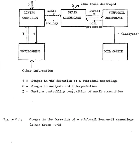
The basis for the interpretation of assemblages of mollusc shells from fossil sites is the ecology of their present-day counterparts (Evans 1972). Two main categories of difficulties occur in this basic assumption, and can be generalised as stratigraphical and ecological. The former includes the changes that the composition of the assemblages undergoes in the course of soil formation and sediment deposition. The latter includes the factors that control the composition of modern faunas and the way in which the influence of these factors has changed with-time (figure 2.1).
4.
3
ENVIRONMENT Heredity
3
V LIVING COI IMUNITY
037
Some shell destroyed • 2 ;11
Death Burial
DEATH
ASSEMBLAGE r---c 1
Ecology Soil
—processes
(Analysis) SUBFOSSIL
ASSEMBLAGE
SOIL SAMPLE
Other information
1 = Stages in the formation of a subfossil assemblage 2 = Stages in analysis and interpretation
3
= Factors controlling comlosition of snail communitiesFigure 2.1. Stages in the formation of a subfossil landsnail assemblage
1964; 1968; 1970; Kerney 1963; 1968; Kerney et Al. 1980; Preece 1980; Preece & Robinson 1984).
Snails offer certain advantages as environmental indicators: they are small; they are plentiful in calcareous soils; and there is a limited number of species covering a wide range of habitats. Snails are particularly sensitive to changes in land use and are good indicators of open ground, shade and moisture. Environments that appear different to humans may seem identical to the snail. The environments need to be considered at a micro-level and consideration given to the factors important to the snails such as availability of calcium carbonate and lack of disturbance. The converse is also true: apparently identical habitats will contain different faunas because of small specific differences.
039
will be reflected in the 6 13 C of the organic and inorganic components of the shells (Goodfriend pers.comm. 1985).
The ability of snail species to live in an apparently wide range of environments and adapt to a new macro-environment by locating a suitable micro-environment must be considered when assuming that shells from fossil sites reflect the same environments as modern snails. In order to obtain the most accurate picture of a past environment the structure and species diversity as well as the particular species present should be examined.
Evans (1972, 207ff) discusses the mechanisms by which snail shells become incorporated into soils and deposits. Shells will only be preserved in calcareous environments and Evans divides calcareous soils and sediments into three groups: soils formed by in situ weathering of the parent material, colluvial deposits or sediments formed by accumulation (e.g. hill wash, water lain sediments and wind
lain sediments), and colluvial soils (weathered as they accumulate). The formation of the deposit has an important bearing on the population of shells found within it. An extreme case of this is a hill wash deposit which could contain shells that were originally some distance from the place of deposition and possibly are not contemporaneous if reworked material is involved. Soils formed by weathering could also contain reworked material if the parent material were a colluvial deposit formed appreciably earlier than the weathering episode. These problems are discussed further in chapter 2.4.
2.22 Ecology of species in this study.
pomatia, Pomatias elegans and Xeropicta vestalis.
Cepaea nemoralis
This species is found over much of the British Isles but is absent from the north of Scotland and the Outer Isles. Its distribution is controlled by its preference for lime and calcium carbonate (Boycott 1934). It occupies a variety of habitats: woods, hedges, marsh, grassland and dunes. It is generally found in drier and warmer habitats than C.hortensis. C.nemoralis is found in Hoxnian and Eemian Interglacial deposits and appears in the early Post-glacial (Boreal or Pre-boreal). Its present distribution is smaller than when it attained its maximum distribution about 4000 bp, probably due to the clearance of forest by prehistoric agriculturalists (Cain & Currey 1963). The diet of C.nemoralis consists predominantly of senescent or dead plant material (e.g. Taraxacum officinale and Ononis repens) .(Richardson 1975) with green material from Urtica dioica (Wolda et al. 1971). It is also recorded as eating algae, animal remains and fungi (Wolda et al. 1971). They feed and rest on the lower vegetation at ground level and up to 0.5m above depending on the plants that are present.
Cepaea hortensis.
041
found in the vicinity of trees and shaded areas. Cain & Currey (1963) suggest this is because competition between the species is less important in these micro-environments. In areas beyond the range of C.nemoralis the habitats that it would occupy in more southerly areas are taken over by C.hortensis.
Since the prehistoric period the distribution of C.hortensis has become reduced. Studies of the fossil dunes at Northton (Evans 1971) showed it to be common in the pre-Iron Age levels but to have declined at the time when Cochlicella acuta and Helicella itala were introduced. The modern fauna in the study area at Hayle Towans shows a similar composition with C.nemoralis, C.acuta and H.itala common whilst C.hortensis rare. The decline of C.hortensis was also evident in Co.Mayo, Eire; 397. of the Cepaea shells from a fossil deposits at Carrowmore were C.hortensis, whereas in the modern sample from the nearby site of Graffy there was no evidence of living C.hortensis.
Arianta arbustorum
This species is widespread in Britain but is rare in Ireland where it is restricted to the north. It is found in a range of habitats such as meadows, herbage, woods and hedgerows, but is always restricted to damp places. The preference for damp areas is due to its low degree of resistance to drought. Arianta can be found in colder places than Cepaea and, therefore, can be found in thick vegetation, valley bottoms and north facing slopes.
Helix pomatia
of within shell variations to be undertaken (section 5.3). The large size of H.pomatia has also led to its being widely used as a laboratory animal in education and research; its morphology and ecology are, therefore, well studied.
Pollard (1975b) showed that H.pomatia feeds on live plant material in fresh condition, particularly Cenilrea species, often above the ground surface. Juveniles and young adults were seen less frequently and tended to occupy a habitat with more cover, particularly by concealing themselves under leaf litter and vegetation at ground level.
Pomatias elegans
043
Xeropicta vestalis
One species of snail not found in Britain was used in part of the study of fossil shells, namely X.vestalis. This species is common throughout the Mediterranean region of Israel, both in the hills and
in the Coastal Plain (Heller & Tchernov 1978). It is frequently observed on low vegetation and grass and is found in groups on stems and branches particularly during warm weather. It exhibits banding morphs similar to those found in Cepaea; the number of bands varies from nought to six.
Xeropicta vestalis is the commonest snail found in fossil assemblages in the eastern Mediterranean and shifts occur in its morph frequencies from the Palaeolithic to recent layers, particularly a rise and fall in the numbers of the unbanded morph
(Heller & Tchernov 1978).
2.3 ENVIRONMENT AND ECOLOGY OF MODERN SAMPLE SITES 2.31 Introduction
The samples used for the comparative part of the study of chemical and stable isotope composition were collected at three sites in the British Isles selected to cover a range of geologies and the types of site that are most frequently encountered in fossil deposits. The sites were open woodland on chalk at Dldlands Wood, Surrey, calcareous sand dunes at Hayle, Cornwall, and an open site on tufa at Graffy, Co.Mayo (figure 2.2).
2.32 Oldlands Wood, Surrey
Binnel Point
Hayle
Towans
Figure 2.2.
Location of modern and fossil
sample sitein
the045
and East Horsley, Surrey (G.R. TQ 106517). The site is on the dip slope of the chalk escarpment of the North Downs, on gently sloping north facing ground 105-180m above O.D.
Geology
The geology of most of the wood, including the collection site, is Upper Chalk (H5— '). Tertiary Beds (Reading and Thanet) overlie the chalk about 400m north of the wood on the southern edge of the London Basin. To the south the dip slope is capped by Fleistocene deposits. South-west of the wood and including a small area of the wood are Netley Heath Deposits consisting of sand and very coarse gravels containing blocks of Greensand, Red Crag and flint. To the south-east are deposits of Clay-with-flints which extend over much of the adjacent Ranmore Common. The boundary between the Netley Heath Deposit and the Clay-with-flints is a dry valley which is incised to expose the Upper Chalk and is partly filled with valley gravel. All the lithologies except the chalk yield acid soils and no molluscs were found from any natural habitats on them. Exposures of chalk were observed within the wood and to the north; samples were taken from both of these sites (sample numbers Ch.S3, Ch.S4).
Soils
Two soil pits were dug at the collection site; descriptions of the horizons are given below. The soils are classified as rendzinas.
Soil Description: Site 1
0-2cm Litter
Consists of slightly decayed material, all derived from leaves. Collected prior to 1984 leaf fall therefore no recent leaves found.
3-12cm AH1
Dark brown (10YR 4/3) silty loam, roots common, angular fragments of flint (maximum dimension (max.dim.) 2cm)
12-40cm AH2
Dark yellowish brown (10YR 4/4) silty clay loam, angular fragments of flint (max.dim. 2cm) and rounded chalk fragments (max.dim. 0.5cm).
40+cm BH
Yellowish brown (10YR 4/4-5/4) silty clay loam, inclusions as 12-40cm.
Soil Description: Site 2
0-2cm Litter
L
Consists of slightly decayed plant material, largely pine needles but some beach leaves. Collected prior to 1984 leaf fall therefore no recent leaves found.
2-3cm Litter F
Partly decomposed material, some original plant material visible.
3-10cm AH1
Light greyish brown (10YR 5/2-6/2) silty loam, many roots, rounded chalk frag. (max.dim. 1cm), some finer particles of chalk influencing the colour.
10-1'5cm AH2
Greyish brown (10YR 5/2) silty clay loam, roots, rounded fragments chalk (max.dim. 1cm), some finer particles influencing colour.
15-20cm Cr
Weakly consolidated, little altered Chalk, many angular fragments.
20+cm R
047
Site 1 appeared to be disturbed and is probably not representative of the area.
Particle size analysis, and organic and calcium carbonate contents were measured (tables 2.1 to 2.4).
Particle size and loss on ignition
Site 1 (1) (2) (3)
Sample Type Depth LOI (7.) CaCO 3 Sand (%) Silt (%) Clay (%)
1 AH1 3-12 13.7
2 AH2 12-40 10.0
3 BH 40+ 7.5
(1) Loss on ignition (2) Percentage of whole sample (3) All fractions
Table 2.1 Particle size and LOI for samples from Oldr - ands Wood Site 1
Site 1 Sand Fractions (%)
Sample Type Depth >lmm 1.000- 0.500- 0.250-
0.125-0.500mm 0.250mm 0.125mm 0.063mm
1 AH1 3-12 5.7 7.1 20.2 25.0 9.9
2 AH2 12-40 5.2 4.6 15.4 30.4 14.1
3 BH 40+ 3.5 3.9 13.7 39.1 23.9
Table 2.2 Sand fractions for samples from Oldlands Wood Site 1.
Site 2 (1) (2) (3)
Sample Type Depth LOI (%) CaCO 3 Sand (7.) Silt (%) Clay (1)
4 AH1 3-10 14.4 28.0 32.3 55.3 12.7
5 AH2 10-15 9.3 45.0 63.1 21.8 15.0
6 Cr 15-20 7.3 71.0 60.6 5.3 34.6
(1) Loss on ignition (2) Percentage of whole sample (3) All fractions
3.0 67.9 25.1 6.9
0.0 69.7 22.5 7.8
Table 2.3 Particle size and LOI for samples from Oldlands Wood Site 2.
Site 2 Sand Fractions (i)
Sample Type Depth >lmm 1.000- 0.500- 0.250-
0.125-0.500mm 0.250mm 0.125mm 0.063mm
4 AH1 3-10 5.5 3.3 5.4 11.1 7.0
5 AH2 10-15 14.4 6.1 9.2 19.6 13.8
6 Cr 15-20 20.8 10.0 7.5 14.7 7.6
Table 2.4 Sand fractions for samples from Oldlands Wood Site 2.
Site 2 is considered to be representative of the wooded area. It shows increasing CaCO3 content down the profile but access to the calcium carbonate is restricted by the litter layers. Site 1 shows very low levels of CaCO 3 and must represent a dump or artifidal deposit.
The only source of CaCO3 will be the chalk present as exposures or particles in the soil; it all has a zero I4 C content.
Drainage
049
History of the Wood
The area was used in the nineteenth century for lime burning. Two areas at the south end of the wood are called Kiln Field Coppice and Pump Pond Wood; a number of disused pits are located near Kiln Field Coppice. Two embanked track ways run roughly north-south through the wood. This evidence suggests chalk pits, kilns and slaaing ponds, and a mineral line running north to the main railway at East Horsley. The area is shown as woodland on late 19th century maps and the presence of kilns also suggests a traditional area of woodland. The fields surrounding the wood on the north and south sides are arable, whilst to the east and west are further areas of woodland and grassland.
Vegetation
The wood is a mixture of pine, ash and beech; the trees are not fully grown and include saplings. The density of the trees combined with the litter layer inhibits the growth of ground cover and other plants below the canopy. The wood is divided by a number of open areas that act as fire-breaks; these contain a wider diversity of plant
species.
Sampling Sites
051
very few were seen higher in the vegetation at the edge of the wood and fire-break.
Molluscan Fauna
Pomatias elegans and C.hortensis were common and large numbers were available for collection, C.nemoralis was much rarer and only recently dead shells were collected. The large shells of H.pomatia were also rare and had to be collected over a wide area, but they were all from within 50m of the sample area. Study of the distribution of species within the environment showed that each of the four collected species occupied a distinct niche.
Pomatias elegans was found within the litter layer and in the top 5cm of the soil horizon; it was not observed on living plants and only rarely on or above the litter surface. C.nemoralis and C.hortensis were found on the litter surface or occasionally just below it. They were also observed on living plant material but never far above the ground. H.pomatia appeared to spend its active periods at the edge of the wooded area, generally at ground level. It is known to bury itself in the litter layer during inactive periods and hibernation.
2.33 Hayle Towans, Cornwall
053
and quartz sand, and there is an appreciable organic component in soils that have formed on stable surfaces. The dunes are undulating and rise from sea-level to 57m above O.D. at their highest point.
Sample Sites
Five sites were studied and detailed chemical and particle size analysis was undertaken on samples from sites 2,4 and 5. Figure 2.4 shows the location of the sites.
Site 1 Grid Ref.: SW 552382 +5m O.D.
Location: Near a series of old quays on the western edge of the main area of dunes. The area was open-ground with some low scrub nearby. Site 2 Grid Ref.: SW 557388 +25m O.D.
Location: On the cliff edge above Black Cliff, on the western side of a stone and bank wall. This site was in the area where the slate bedrock rises as a ridge at right-angles to the coast. The sand cover is much thinner with a more even surface.
Site 3 Grid Ref.: SW 565396 +20-25m D.D.
Location: On the top of the dunes immediately above high water mark. The area is open dune, stablised by vegetation in most places but with some exposed sand.
Site 4 Grid Ref.: SW 566395 +30-35m O.D.
Location: Inland from Site 3, an area of unstable dunes. Samples were taken from the present surface (PS) and a buried stable soil horizon
(BS).
Site 5 Grid ref.: SW 566386 +40-45m O.D.
The sand dunes overlie fine grained slates and sandstones that form the metamorphic contact aureole around the granite to the south and west. A band of alluvium has developed on the south side, between the dunes and the slate, there is also valley gravel and head deposits at this point. Two smaller areas of blown sand are found nearby. One lies west of the River Hayle and the other east of the main area and separated from it by a ridge in the slate bedrock. The alluvium to the south may be due to the flooding of the area behind the sand-dunes by tidal waters coming up the River Hayle; the alluvium is only 5-10m above O.D. As the surrounding rocks are all acidic the dunes represent an isolated area of calcareous deposits and have developed a rich molluscan fauna.
Soils
Soil pits were dug at Sites 1,2 and 5; descriptions of the horizons are given below.
Soil Description: Site 1
0-3cm Turf
L
Closey knit coarse grass. 3-13cm
Loamy sand, contains many roots. 13-23cm
Slightly loamy sand. 23+cm
055
Soil Description: Site 2
0-2cm Turf
Closely knit coarse grass. 2-8cm
Dark yellowish brown (10YR 4/4) loamy sand, some roots and angular stone fragments (max.dim. 2cm).
8-28+cm
Dark greyish brown (10YR 4/2) loamy sand, some angular stone fragments (max.dim. lcm).
Soil Description: Site 4
Present surface: Greyish brown (10YR 5/2) sand, occasional grass plant and roots.
Buried surface: Light yellowish brown / yellow (10YR 6/4-7/6) sand.
Soil Description: Site 5 0-5cm
Dark yellowish brown (10YR 4/4) sand. 5-20+cm
Yellowish brown (10YR 5/4) sand.
Particle size and loss on ignition
(1) (2) (3)
Site No. Sample Depth LOI (%) CaCO 3 Sand (%) Silt (X) Clay (%)
Site 2 7 2-8 12.8 44.8 86.4 7.3 6.3
8 8-25+ 6.6 49.1 86.5 7.7 5.8
Site 4 9 PS 2.1 77.3 99.1 0.9
10 BS 4.8 71.7 97.1 0.8 2.1
Site 5 11 0-5 6.6 69.2 96.7 3.3 0.0
12 5-20+ 1.9 69.6 98.9 1.1 0.0
Table 2.5 Particle size and LOI for smples from Hayle Towans Sites 2,4 and 5.
Sand Fractions (%)
Site Sample Depth >lmm 1.000- 0.500- 0.250- 0.180- 0.125-
0.090-0.500 0.250 0.180 0.125 0.090 0.063
2 7 2-8 0.1 2.8 45.6 20.8 9.5 3.0 4.5
8 8-25+ 1.3 3.7 47.1 21.5 8.0 2.1 2.7
4 9 PS 0.1 5.1 69.1 20.6 3.9 0.2 0.1
10 BS 0.4 4.0 53.8 29.4 8.0 0.9 0.5
5 11 0-5 0.4 6.5 64.1 20.7 4.3 0.6
12 5-20+ 0.1 2.7 64.7 26.0 5.0 0.3 1.2
Table 2.6 Particle size analysis of sand fraction for samples from Hayle Towans Sites 2,4 and 5.
Distribution of CaCO 3 by grain size
Site Sample Depth >1mm 1.000- 0.500- 0.250- 0.180- 0.125-
0.090-0.500 0.250 0.180 0.125 0.090 0.063
2 7 2-8 34.1 63.2 46.2 45.7 30.7 25.6 28.0
8 8-25+ 27.1 64.2 61.9 51.6 26.4 27.5 24.7
4 9 PS 77.7 86.2 81.3 69.1 58.8 48.6 55.6
10 BS 97.3 90.2 78.6 66.8 60.4 63.2 60.4
5 11 0-5 93.3 82.4 74.5 64.1 56.0 47.5
12 5-20+ 100.0 84.6 74.1 63.1 54.3 61.2 60.7
057
Analysis of particle size data
Site Depth Median Graphic Std Dev. Skewness Skewness Sorting (Md) Mean (M.) (Si) (SK1)
2 2-8 2.55 3.20 1.68 0.82 Strong-fine Poor 8-25+ 2.45 2.87 1.54 0.76 Strong-fine Poor 4 PS 2.35 2.37 0.30 0.14 Fine V.well
BS 2.45 2.52 0.39 0.32 Strong-fine Well 5 0-5 2.35 2.40 0.37 0.29 Fine Well
5-20+ 2.40 2.45 0.29 0.34 Strong-fine V.well Calculated using methods in Folk (1974)
Table 2.8 Analysis of the particle size data for samples from Hayle Towans Sites 2,4 and 5
The particle size analysis of the soils shows there are three different types of sediment defined by different degrees of soil development. The least developed are represented by Site 4 PS
(present surface) and Site 5 5-20+; the former is an erosion surface, the latter the layer below a humic level. The second group are stable surfaces but with minimal soil development; Site 4 BS (buried surface) and Site 5 0-5 are of this type. The final group are well developed loamy sands; Site 2 2-8 and Site 2 8-25 are of this type. Site 2 was an area where the sand was thinner and a more permenant surface had become established; the degree of soil development suggests that this is a long established surface and that its level and exposed position keep it free from further inundation by sand. This development of Site 2 is reflected in the high organic content and the lower level of CaCOm (45-49%) compared to the other sites
to be largely formed from fragments of marine shell but also to include some terrestrial shell fragments and spines of echinoderms. The samples from Site 4 PS had fragments of shell in which the pigments were still fresh. This suggests that the dunes are not only active if exposed but that fresh material is still being blown from the wide area of the beach present at lowtide (210ha).
The 14 C age of a sample of calcareous sand from site 5 was 6320i20 bp (0-2???), this corresponds to 46% of the activity of uncontaminated modern wood.
Drainage
The highly permeable sand dunes are freely drained and except in areas closely associated with the metamorphic slates the waters will be alkali or neutral. The reduced level of CaCO 3 at Site 2 may be associated with the underlying slates which produce acidic groundwaters. The Towans area is cut by the River Hayle and the Red River which drain the surrounding countryside. The slates underlying the Iowans must act as an impermeable horizon allowing water that percolates through the dunes to flow along the bedrock surface on the dipping strata towards the sea or the two main rivers. If the base of the dunes is below present high water level saline water may also be present below the sand dunes forming a marine phreatic zone.
The free movement of waters should preclude any post-depositional changes occuring, but as will be shown for the site at Netanya these can still occur under certain conditions.
History of the Area
059
documented, but one can combine data obtained by excavations and analyses of molluscan assemblages at Gwithian (eastern end of the Iowans) (Megaw et al. 1961; Spencer 1975), Newquay (Kennard & Warren 1903; Woodward 1908) and elsewhere (Evans 1971; Simpson 1966) to reconstruct their evolution.
During the last interglacial period a raised beach developed; in some areas this is covered by wind-blown sand that is completely decalcified in places (Reid & Flett 1907). The sand, which is partly lithified, is overlain by head and solifluxion deposits of clay and angular stones. The top of the head deposit is a band of clayey sand, possibly a post-glacial ground surface; this is covered with wind-blown sand. Mesolithic occupation is recorded by the frequent artefacts found in the Iowans area (Spencer 1975).
from the beach at lowtide and that the wind strength is critical in controlling the size of particle that is moved. Destruction of shells to this size is by wave action. The inundation of stable soil surfaces shows that large scale movement of new and reworked material is continuing.
The use of the area in the Medieval period for arable fields (Fowler & Thomas 1962) and the presence of churches at Gwithian and Fhillack suggest that extensive use was made of the area. The Towans have remained open spaces and are now largely used for recreation. This has helped to stablise some areas but has led to the rapid erosion of access areas. In the nineteenth century the central area was occupied by an explosives factory and it may be that the large unvegetated area left by this, combined with present use, has led to much of the destablisation and inundation of the old land surfaces.
Vegetation
The stable areas of the dunes are covered with halophytes such as Manam grass. Sites 1 and 5 had small shrubs and trees, whilst at Site 2 the long period of stability has produced a more diverse flora in the thick turf.
Molluscan Fauna
061
Candidula intersecta Cernuella virgata Helicella itala Cochlicella acuta Ashfordia granulata Trichia hispida Cepaea nemoralis Cepaea hortensis Helix aspersa Arianta arbustorum
Table 2.9 Terrestrial mollusc species observed on Hayle Iowans.
Cepaea nemoralis was active at ground-level on both the turf and the dune surfaces but rarely on open sand. It was found sheltering in vegetation and under walls and stones.
2.34 Graffy, Co.Mayo, Eire
Graffy is an extensive area of calcareous tufa 6.6km north-west of Swinford, Co.Mayo (Grid Ref. G 346047, Lat.53° 59'N,Long. 8° 59'W) (figure 2.5). The site is on the lower slopes on the southern side of the Ox Mountains, about 75m above O.D. The total area of tufa is c.2ha and its maximum observed depth was 4.30m. There is a small lake (Marl Lough) on the north-west side of the area and this has at times produced marl and sedge peat deposits which interdigitate with the tufa at the lake margin.
Geology
063
to the north are the Ox Mountains, an area of intrusive rocks that are surrounded by metamorphic schist and gneiss. During the last glacial period ponds of water that had formed behind ridges of drift (associated with the "Young Ice" and including large quantities of limestone) drained through the drift and became calcareous as they did so (Frank Mitchell, unpub.notes). The change
in external conditions as the water emerged at the spring head led to the precipitation of tufa; as this occurred atmospheric carbon dioxide becames incorporated and the final isotopic values depend on the relative contribution of dissolved carbonate and carbon dioxide. The area around the tufa has extensive areas of peat growth which is exploited for fuel in places.
The lake was formed by a drift ridge which blocked the natural outflow of the stream. The tufa contains some till which slumped into it.
Soils
The modern samples were collected from the base of a shallow quarry from which tufa and marl had been extracted for spreading on the surrounding acid farm soils. Many of the molluscs were on exposed tufa or areas where only a thin soil had developed. The ground between the quarries had a more developed soil some 10-15cm thick with a peaty texture. The thin soil is dominated by tufa and contains 85-907. calcium carbonate; much of the remainder is organic material. Tufa in exposed areas is 97-987. calcium carbonate with the remainder formed by a mineral component.
wood. Part of the depletion is due to the snails occupying an exposed surface of fossil tufa. Fossil samples are less subject to problems from tufa depleted in I4 C. Provided the tufa is occupied soon after deposition it will only be depleted by the disssolved carbonates present in the groundwater.
Drainage
The high rainfall for the area (120-140cm per year) has led to leached soils; the vegetation and peaty soil indicate an acid environment despite the alkali tufaceous subsoil. The water table is
immediately below the quarried area and 2-3m below ground level; a small stream drains down the slope above the tufa and into the lake. The presence of the high water table and the lake suggest movement of groundwaters bringing carbonate from lower levels of the tufa or limestone.
History of the Area
During the period of tufa growth conditions varied to allow the development of soils (no tufa growth and some erosion), peats
065
Molluscan Fauna
The most prominent living snails were C.nemoralis; no modern C.hortensis were seen although present as fossil shells. P.eleoans and H.pomatia are unknown from Ireland.
Cepaea nemoralis is assumed to live on the tufa surface and in the low vegetation; hibernation is probably in the vegetation as burrowing is difficult in the tufa surface.
2.4 FOSSIL SITES 2.41 Introduction
The samples used for the study of sub-fossil shells were collected from six sites in Britain and Ireland (figure 2.2). They were chosen because they were independently dated and because of the amount of palaeoenvironmental data that was already available. Fieldwork was undertaken at three sites (Carrowmore, Caerwys and Newlands Cross) and material from the other sites (Castlethorpe, Binnel Point and Inchrory) was made available by Dr Richard Preece of the Godwin Laboratory, Cambridge.
2.42 Carrowmore, Co.Mayo, Eire.
dating.
Geology
The geology of the area is described under Graffy in the preceding section.
Drainage
The site is cut by a small stream which has deeply incised the tufa in places. At the bottom of the slope the stream flows less freely and much of the area is marshy and waterlogged. The lower levels of the tufa at Site A were also waterlogged and the water welled out where the tufa had been cored. These factors, combined with the heavy rainfall in the area, suggest that there will be leaching and movement of ions within tufa and any associated shells.
Description of stratigraphy
The maximum observed thickness of tufa was at Site A where 7.15m of deposits formed from channels and flowng water were observed.
Site B was 3.30m thick and probably underlain by clay (found by augering). It contained eleven organic rich horizons in the main section; an additional one was observed at a second section. The tufa between these horizons was generally soft but was nodular and hard in two horizons. The position of the organic horizons and the nodular tufa is shown in figure 2.6).
History of the site
in adjacent areas of the site. The deposits appears to have accumulated over a short period of time, probably about 6000 bp to 4500 bp (Preece pers.comm.1986). The snail shells in the clean tufa suggest the area contained some standing water and trickling streams. Only the top 20cm showed any marked change in the snail assemblage and this is interpreted as being somewhat later than the main deposit but there was no evidence of a hiatus between the two.
2.43 Newlands Cross, Dublin, Eire
Newlands Cross is a shallow (1.20m thick) deposit of tufa on the western edge of Dublin (0 078 297; lat.53° 18'N, long.6° 23'W) and about 80m above O.D. The tufa was originally exposed during road construction work but can now only be sampled by excavation. The basic stratigraphy is tufa overlying a buried soil; there is then a second layer of tufa and finallly a diamicton of clay and angular limestone fragments. The shell samples came from the buried soil and were collected by excavating a 0.7m x 0.7m section through the
deposit.
Geology