122 | P a g e
SPATIAL DIVERSITY TECHNIQUES IN MIMO WITH
FREE SPACE OPTICAL COMMUNICATION
Ruchi Modi
1, Vineeta Dubey
2, Deepak Garg
3ABESEC Ghaziabad India, IPEC Ghaziabad India, ABESEC,Gahziabad (India)
ABSTRACT
In this paper we have described Multiple Input and Multiple Output (MIMO) with Free Space Optical (FSO)
link using spatial diversity technique. Here we have used different combining techniques at the reception side to
improve the overall system performance. Channel model used here is Gamma-Gamma model which can be used
for high to low turbulence environment.
Keywords: Combining Techniques, MIMO, SISO.
I INTRODUCTION
In telecommunication, Free Space Optics [FSO] provides an optical communication technology which uses light
energy to transmit the information from one point to another point. This technology is very useful where it is
difficult to incorporate the optical fiber due to structure of the surface or due to maintenance. Like fiber, FSO
uses lasers to transmit data, but through the open air instead of using closed fiber cable. FSO is capable of
sending up to 1.25 Gbps of data, voice, and video communications simultaneously through the air [1]. Short
Range line of sight optical links have the potential for providing high bandwidth access to larger wired network
as well as they can be used to link intranets within the corporate campuses. FSO is attractive compared to RF
due to several reasons. First, optical beams are very directive with beam width on the order of 10mrads so
spatial isolation from other potential interferes is maintained. Secondly, there is no license is required for optical
bandwidth. Third, it provides high level of security with data speed of upto 1.25 Gbps. Fourth its maintenance is
low and can be installed behind the windows, so roof top is required [2]. Systems using Multiple Transmit and
Multiple receive Antenna are known as Multiple Input and Multiple Output (MIMO) System. This wireless
technique has greatly improved the capacity and range of wireless communication channel. MIMO systems
constructively explores multipath propagation by using different transmission path to the receiver, which
provides redundancy of data thus increases the reliability of transmission. This technique is also useful for
increasing the transmitted data rate. MIMO system has attracted users significantly because it offers high
speedreliable data range at the same power and bandwidth [3]. MIMO system can also be used for FSO system.
As MIMO uses multiple transmit and receive antenna so at the transmitter several laser diode are used (as laser
diodes convert electrical information into optical data stream) for transmitting the data and at the receiver
several photo diodes are used to collect the transmitted information.
In this paper, we describe an optical wireless terrestrial link in which we have used the concept of MIMO with
free space optical communication. Different combining schemes are used at the receiving side to evaluate the
performance of link with 2x2 and 4x4 MIMO systems.
123 | P a g e
MIMO system uses multiple transmitters and multiple receivers, which has been shown in Fig 1.
Fig.1.Multiple Input and Multiple Output System in FSO
III CHANNEL MODEL
Optical Channel is affected by parameters like scattering and turbulence. Gamma-Gamma PDF closely models
experimental results over low to high turbulence strengths and is most suitable for studying link performance
parameters for slow fading conditions.
The irradiance of optical field is defined as the product of two random processes, i.e. I = I x I y, where Ix arises
from large scale turbulent eddies and Iyfrom small-scale eddies. Specifically, gamma pdf is used to model both
small-scale and large scale fluctuations, leading to the so-called gamma-gammapdf, i.e. [4]
I>0 (1)
Where Ka (.) is the modified Bessel function of the second kind of order a. Here, α and β are the effective
number of small-scale and large-scale eddies of the scattering environment. These parameters can be directly
related to atmospheric conditions according to
Where and . Here is the optical wave number, is the wavelength
and D is diameter of receiving collector aperture lens. Cn2 stands for index of refraction structure parameter and
is altitude dependent. Several Cn2 profile models are available in the literature, but the most commonly used is
the Hufangle-Valley model is described by
Cn2(h)=0.00594(V/27)2(10-5h)10exp(h/1000)+2.7x10-6exp(-h/1500)+Aexp(-h/1000) (4)
Where h is altitude in meters (m), V is rms wind speed in meters per second (m/s) and A is the nominal value of
Cn 2
(0) at the ground in m-2/3 for the FSO links near the ground. Cn
2
can be taken approximately 1.7x10⁻⁴m
-2/3
during daytime and 8.4x10⁻¹⁵m-2/3 at night. In general Cn
2
varies from 10-13m-2/3for strong turbulence to 10-17m
124 | P a g e
IV DIVERSITY COMBINING TECHNIQUES
There are various combining techniques used to combine the signal from multiple diversity branches available
in literature such as Selection Combining (SC), Equal Gain Combining (EGC) and Maximal Ratio Combining
(MRC) [5].
4.1 Selection Combining
In selection combining technique the best signal among all of the signals received from different nodes is
selected at the receiver end. As each element, there is an independent sample of fading process, so that the
signal with high SNR is chosen from all the branches at receiver end.
4.2 Equal Gain Combining
In equal gain combining the received signals are summed up coherently with equal weights at all the received
diverse signals. This technique gives better performance in terms of BER as compared to selection combining
technique.
4.3 Maximal Ratio Combining
In maximal ratio combining each signal branch is multiplied by a weight factor that is proportional to the signal
amplitude. Which means signal with high SNR will be multiplied by a weight i.e. it is amplified, while the
signal with low SNR will be attenuated. In telecommunications, maximal ratio combining is a method of
diversity combining in which the signal from each channel are added together and the gain of each channel is
made proportional to the RMS value of signal and inversely proportional to the mean square noise level in that
channel. Different proportionality constants are used for each channel. It is also known as ratio squared
combining. Maximal ratio combining is the optimum combiner for independent AWGN channels. In this
combining the signal from all the branches are weighted according to their individual SNRs and then summed.
V. SYSTEM MODEL
MIMO-FSO link has been simulated in RsoftOptsim for different combining schemes as discussed above i.e. for
SC, EGC and MRC. The signal to noise ratio (SNR) Vs bit error rate (BER) curves have been found each the
combining schemes.
5.1
2x2 MIMO FSO Link-
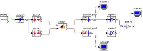
In Fig 2, we have used 2x2 MIMO link. There are two laser diodes and two PIN detectors and the channel is
modeled as gamma gammapdf which has zero mean i.e. μ = 0 and variance σ 2 = No/2, which has simulated
using Optsim- Matlabco simulation. Pseudo random sequence generator which generates the random data
pattern at bit rate of 1 Gbps , rectangular electrical driver/NRZ driver which converts the data pattern into
electrical form and the direct modulated laser source at 1550nm. Two laser diodes have been used at transmitter
end to transmit the same data, which has been collected at two photodiodes via optical channel. The converted
electrical signals have been assigned weights according to the combining techniques used and then a combiner
125 | P a g e
Fig. 2.2x2 MIMO Simulation Model
5.2
4x4 FSO MIMO Link
The link has been designed for 4X4 MIMO FSO system shown in figure 3. Here the channel matrix is of 4X4
and the length of the channel is 1 Km. The PRBS generator generates randomdata which is converted into
electrical domain through NRZ electrical driver. The NRZ driver modulates the direct modulated laser source.
The output from the laser source is passed throughthe channel which is modeled as lognormal having
variance<1. After the channel there is detector which is PIN Diode. It converts the optical data into the
electrical form. We can analyze the performance of the link by measuring the eye pattern and bit error rate.
Fig.3: 4x4 MIMO Simulation Model
VI SIMULATION AND RESULTS
6.1
2x2 MIMO FSO LINK
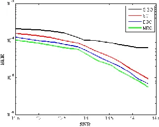
In Fig 4, BER performance comparison for SISO, SC, EGC and MRC for 2x2 FSO- MIMO system has been
shown. Here, we can see that for BER of 10-3 the SNR requirement is 13db, 12.5 dB, 11.5dB and 11dB for
SISO, SC, EGC and MRC respectively. Hence we can observe that MRC provides the SNR improvement of
126 | P a g e
Fig. 4.
BER performance of SISO and different combining schemes for MIMO
6.2
4x4 FSO MIMO LINK
In Fig 5, BER performance comparison for SISO, SC, EGC and MRC for 4x4 FSO- MIMO system has been
shown. Here, we can see that for BER of 10-4 the SNR requirement is 14.5dB, 13 dB, 12.5dB and 11.5dB for
SISO, SC, EGC and MRC respectively. Hence we can observe that MRC provides the SNR improvement of
3dB over SISO system.
Fig 5.BER performance of SISO, SC, EGC and MRC for 4x4 MIMO system
VII. CONCLUSION
At SNR of 12dB, we have the BER is around 10-3 for the Equal Gain Combining case in 2X2 MIMO and 10-4
for the Equal Gain Combining case for 4X4 MIMO FSO link. Hence we can conclude that the performance of
4X4 MIMO FSO link is better than 2X2 MIMO FSO link and MIMO-FSO system guarantees the performance
over SISO system.
REFERENCES
[1] www.lightpointe.com
[2] David J. T. Heatley, David R. Wisely, Ian Neild, and Peter Cochrane, “Optical Wireless: The Story so Far,”
IEEE Communications Magazine, vol. 36, no. 12, pp. 72-82, Dec. 1998.
[3] J. Nicholas Laneman and Gregory W. Wornell, “Energy-efficient antenna sharing and relaying for wireless networks,” in Proc. Int. Conf. IEEE Wireless Communications and Networking Conference, September
23-28, 2000, pp-7-12, vol 1.
[4] Marvin K. Simon Mohamed-Slim Alouini, Digital Communication over Fading Channels: A Unified
Approach to Performance Analysis, John Wiley & Sons, Inc., 2000.
[5] Xiaoming Zhu and Joseph M. Kahn, “Free-space optical communication through atmospheric turbulence
channels,” IEEE Trans. Commun., vol. 50, no. 8, pp. 1293–1300, Aug. 2002.
[6] S.M. Navidpour, M. Uysal, and M. Kavehrad, “BER performance of free-space optical transmission with
spatial diversity”, IEEE Trans. Wireless Commun., vol. 6, pp. 2813–2819, Aug. 2007.
[7] “Outage probability of the free-space optical channel with doubly stochastic scintillation”, IEEE Trans.
Commun., vol. 57, pp. 2899– 2902, Oct. 2009.
[8] J. M. Kahn and J. R. Barry, “Wireless infrared communications,” Proc. IEEE, vol. 85, pp. 265–298, Feb.