Mitigation of Harmonics Using Active Power
Filters Based on Hysteresis Current Control
Ch.V.Pujitha1, A.Sambasiva Rao2
PG student (Power Systems and Automation), Dept. of EEE, Gitam University, Hyderabad, Telangana, India 1 Assistant Professor, Dept. of EEE, Gitam University, Hyderabad, Telangana, India 2
ABSTRACT: Presence of power quality problem is one of the most severe power quality problems which leads to power losses in the distribution system, communication interference and sometimes failure of electronic equipment. Shunt active power filter had been a better option to eliminate the current harmonics thus assuring a quality power for distribution. The shunt active power filters generate the harmonic compensating currents which are equal and opposite in polarity to the harmonic currents generated by non-linear loads. Several methods were proposed to generate the reference currents for the VSI in the shunt active power filter which are like id-iq method, synchronous detection
method, synchronous reference frame theory etc. Also the current control strategy is of strict importance as the capacitor voltage changes continuously to the changing load currents. In order to maintain it constant and to produce a switching pulse for the VSI, various current control techniques are used of which the adaptive hysteresis current control had been preferred in this paper. This paper on whole describes about SRF theory for reference current generation and adaptive hysteresis current control and also the importance of DC capacitor voltage to be maintained constant.
KEYWORDS: Shunt Active Power filter, Synchronous Reference frame,Adaptive hysteresis current control scheme.
I. INTRODUCTION
Source current distortion has become a major power quality problem which is caused due to the increased usage of power electronic equipment at the industries and utility power generation site. Also the usage of equipment like SMPS and other domestic electronic equipment has lead to polluted electricity due to their non linear nature [1]. For a better remedial action, the passive filters came into existence which was helpful for the elimination of harmonics. In passive filters they comprise of a LC circuit which are tuned to a particular frequency and used for the elimination of harmonic current when it matches the specified frequency. However it had many drawbacks like resonance, bulky size and fixed compensation. Hence the passive filters are only suitable for low voltage profiles and for the loads which are less sensitive towards harmonics. Adaptive compensation to the fluctuating harmonics could be achieved only by using active power filters which improves the quality of power on the source side so that no other equipment gets damaged further. The amount of harmonic distortion present in the system is generally notified using the terminology of ‘THD’ and ‘TMD’ which have been defined as per IEEE standards. The ‘Total Harmonic Distortion’ is defined as the root mean square value of the ratio of harmonic current to its fundamental load component of current.
= ∑ (1)
In order to maintain a good power factor the reactive power usage should be reduced which can be achieved using APs. Thus because of these advantages the Active power filters are considered. The active power filters are classified into several types, based on their configuration, based on the wiring etc. Based on configuration they can be classified as series active power filter, shunt active power filter, hybrid active power filter, universal active power filter etc.
II. SHUNT ACTIVE POWER FILTER
The shunt active power filter mainly works on the principle of injection of a current of equal and opposite polarity of the harmonic component drawn by the load and injects it at the point of common coupling. It has three most important parts- firstly the voltage source inverter with a capacitor on its DC side, the second one is a reference current generation block which generates a reference value for the compensating current to be added and the third one is the current controlling part which is used for generating the switching pulses for the voltage source inverter and also for maintaining the capacitor voltage to remain constant [2][7].
The configuration of shunt active power filter can be illustrated from the below diagram shown in figure 1.
Fig.1 Configuration of three phase shunt active power filter
From the configuration diagram the following points can be assessed.
The load current comprises of two components i.e., the fundamental component of current and the harmonic component of current as shown in equation 2.
( ) =∑ sin ( +∅ ) (2)
For maintaining the source current to remain sinusoidal the compensating current to be injected is given by equation 3 as follows.
( ) = ( )− ( ) (3)
Thus by compensating the harmonic component, the source current pollution is reduced which helps in damaging of the other equipment near to the source side.
III. IMPORTANCE OF DC SIDE CAPACITOR
The DC side capacitor is mainly used for two purposes- firstly it maintains the DC voltage with small ripple content in steady state and secondly as the energy storage element during the transient state.
In steady state, the real power supplied by the source should be equal to the load power demand and the losses to be compensated. When the load condition changes, this is to be compensated by the DC side capacitor. This causes variations in capacitor voltage. Therefore the reference current must be adjusted proportionally to the real power drawn from the source. Hence the variations in the capacitor voltage are again adjusted to the reference value and the source side real power is equal to that consumed by the load again.
Reference current generation has one of the most significant role which ensures a correct operation of the shunt active power filter. The elements which are sensed are the source voltage, the voltage at the DC side capacitor and the reference value of the capacitor voltage. Using these values the reference currents are generated based on different domain approaches- it can be either frequency domain approach or time domain approaches.
Before learning the reference current generation technique, it is necessary to know the estimation of the reference currents to be generated [7].
The instantaneous source currents can be written as
( ) = ( ) + ( ) (4)
Source voltage is given by
( ) = (5)
The load component comprises of two components namely fundamental component and harmonic component which is represented as
( ) =∑ sin( +∅ )
= sin ( +∅ ) +∑ sin( +∅ ) (6)
The instantaneous load power is given by
( ) = ( )∗ ( ) (7)
= ∗ ∅ + ∗ ∗ ∅ + ∑ sin ( +∅ ) (8)
Therefore ( ) = ( ) + ( ) + ( ) (9) From equation (8),
( ) = ∗ ∅ = ( )∗ ( ) (10)
From equation (10) the source current after compensation is given by
( ) = ( ) ( ) = ∅ = (11)
Here Ism is the current to be supplied by the source for compensation. Since we also have some converter losses
therefore the total peak current to be supplied is
= + (12)
When the SAPF provides the compensating current then the voltage and current come in phase and the voltage remains pure sinusoidal. Thus the fundamental component of the load current should be considered as load current for the active filter to provide harmonic compensation.
For the reference current estimation we have various current compensation techniques which are based on time domain approach and frequency domain approach. The frequency domain approach includes the fast fourier transform technique and the time domain approach includes the p-q technique, synchronous detection method, d-q technique etc. In this paper the application of d-q theory has been discussed [5].
The d-q theory is mainly based on rotating synchronous frame which is derived from the supply voltages using PLL. The active filter currents are obtained from the reference active and reactive component of currents. It is obtained in three steps:
1) The load current in the a-b-c reference frame is converted to α-β stationary reference frame.
3) The rotating d-q reference frame is converted back to a-b-c reference frame.
The conversions are done using the Park’s transformation. The three steps are explained in detail as follows:
In the first step, a transformation is done from the three phase stationary frame to a stationary two phase α-β frame
which is shown in equation (13).
= 1
0 √ √ (13)
The signal is obtained from the signal using the below transformation in equation (14).
= ⎣ ⎢ ⎢ ⎢ ⎡√ √ √ 1
0 √ √ ⎦⎥
⎥ ⎥ ⎤
cos ( − )
cos ( + )
(14)
The axes have an angular frequency of ω in stationary reference frame. The α-β frame is a stationary frame and is
converted to a rotating reference frame with an angular frequency of . Equation (15) shows the conversion of stationary a-b-c frame to rotating d-q frame.
= −sin ( )( ) ( )( ) (15)
The ripple content i.e., the DC offset component and are removed using the low pass filter as shown in equation (16).
= −
= − (16) The third step is to convert back from rotating synchronous d-q frame to stationary reference frame a-b-c using the inverse Park’s transformation as shown in equation (17) and equation (18).
= − (17)
∗ ∗ ∗ = ⎣ ⎢ ⎢ ⎡1 0√
√
⎦ ⎥ ⎥ ⎤ ∗
∗ (18)
The reference currents are fed to current control block to generate the compensating currents.
V. CURRENT CONTROL
Current tracking is one of the most challenging tasks to be performed by the shunt active power filter. The shunt active power filter has to respond continuously to the fluctuating harmonics occurring at the load. This current control is classified into two types namely linear and non linear control [1][3][4].
Some of the linear current control techniques include the ramp comparison current controller using PI, state feedback controller etc. Also we have many non-linear current control techniques which include the intelligent control systems like artificial neural networks based controller, hysteresis fuzzy based controller, one cycle control etc. In this paper the non linear current control technique based on hysteresis current control has been proposed [8][10].
The hysteresis current control mainly works on the principle shown in equation (19).
where is the hysteresis limit in which the current should lie within. Using this hysteresis limit the switching frequency is designated.
Hysteresis current control is again classified into two types namely fixed hysteresis current control and adaptive hysteresis current control. In the fixed hysteresis band method the current oscillates in a fixed current range and also an even switching frequency is attained and for this drawback, the adaptive hysteresis current control has been used. The switching logic is formulated as follows:
If > then upper switch is OFF (s1 is OFF) and the lower switch is ON (s4 is ON).
If < then the upper switch is ON and the lower switch is OFF.
The rate of change of line current affects the switching frequency and the factors that affect the rate of change of line current are the capacitor voltage and the line inductance value of the APF. The current and voltage waveforms for adaptive hysteresis current control is shown in figure 2.
Fig.2 current and voltage waveform with hysteresis band control
From figure 2, we can see that the current ia tends to cross the lower hysteresis band hen switch S1 is ON. The linear
rising current ia+ then touches the upper band where switch S4 is ON. The following equations can be written with
respect to the switching intervals t1 and t2.
= − (20)
=−( − ) (21) Where L is the coupling inductance
and are the respective rising and falling currents
fsw is the switching frequency
− ∗ = 2 (22)
− ∗ =−2 (23)
+ − ∗= 0 (25) Subtracting equation (23) and (22) and substituting (24), we get
− −( − ) ∗= 4 (26) Substituting equation (20) and (21) in (26) we get
( )
− ( ) −( − ) ∗= 4 (27) On solving
− = ( + ∗) (28)
= ( ) (29)
Where m=
∗
Thus the hysteresis band is obtained for the three phases.
VI. SIMULATION AND RESULTS
The total test system consists of a rectifier load with R=10Ω and L=0.1mH. The source voltage is taken as 440V and
the shunt active power filter is used to reduce the harmonics which makes use of synchronous reference frame theory for reference current generation and hysteresis current control for switching of the VSI in the filter[9][10].
The total harmonic distortion without filter is 24.3 %. On using the shunt active power filter the THD is reduced to 4.5% which is acceptable limit as per IEEE standards. The simulation model and the design parameters are specified below. The simulation has been done using the MATLAB/SIMULINK tool of version 7.10 and the results have been obtained. The design parameters are specified in table 1 which comprises of the filter impedance, source impedance, load impedance, the PI controller values and the DC link capacitance values.
Line voltage 440V DC link capacitance 1400μF
DC link voltage 400V
Load impedance Diode bridge rectifier with
R=10Ω and L=0.1mH
Filter impedance R=5Ω and L=2.5e-3mH Kp and Ki 0.1 and 1
Source impedance R=0.5Ω and L= 0.1e-3mH
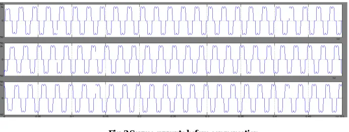
Fig. 3 Source currents before compensation
Reference currents are generated using the synchronous frame theory and the waveforms are shown in figure 4.
Fig4. Reference currents generated
The compensating currents generated are shown in figure 5.
Fig5. Compensating filter currents
Fig6. Source currents after compensation
Fig7. SIMULINK model of shunt active power filter
An Adaptive Hysteresis Current control block has been implemented for the shunt active power filter. The synchronous reference frame controller is used to extract the reference currents from the distorted line currents. This facilitates to improve the power quality parameters such as reactive power and harmonics due to non linear load. The THD of source current after compensation is 4.5% which is less than 5% harmonic limit imposed by IEEE-519 and IEC-6000-3 standard.
REFERENCES
[1] Performance Analysis of Adaptive Band Hysteresis Current Controller for Shunt Active Power Filter a. Smruti Ranjan Prusty1, Saswat Kumar Ram2, B.D.Subudhi1 and K.K.Mahapatra2. b. 1 Department of Electrical Engg., National Institute Of Technology, Rourkela-769008, India
c. 2 Department of Electronics & Comm. Engg., National Institute Of Technology, Rourkela-769008, IndiaEmail:[email protected], [email protected]
[2] L. A Moran, J. W. Dixon, "Active Filters", Chapter 33 in "Power Electronics Handbook", Academic Press, August 200 I, pp. 829-841.
[3] Kazmierkowski M.P; Malesani L.;"Current Control Techniques for Three-Phase Voltage-Source PWM Converters: A Survey", IEEE Transactions On Industrial Electronics, Vol. 45, No. 5, October 1998
[4] L. Zellouma; A Omeiri; S. Saad "Shunt Active Power Filter for Current Harmonics Suppression Using Hysteresis Control", Asian Journal of Information Technology, Vol. 6, Issue 4,pp 436-440, 2007
[5] Zaveri N. ; Mehta A; Chudasama A "Performance Analysis of Various SRF Methods in Three Phase Shunt Active Filters", Fourth International Conference on Industrial and Information Systems, letlS 2009, 28 - 31, Sri Lanka, pp.442-447 December 2009.
[6] V.Soares; P.Verdelho; GD.Marques "An instantaneous active and reactive current component method for active filters," IEEE Trans. Power Electron., vol. 15, no. 4, pp. 660-669, July- 2000.
[7] Zouidi, A Fnaiech, F. AI-Haddad, K. "Voltage source Inverter Based three-phase shunt active Power Filter: Topology, Modeling and Control Strategies" IEEE International Symposium on Industrial Electronics, Vol. 2, pp 785, 9-13 July 2006
[8] Sasan Zabihi, Firuz Zare "An Adaptive Hysteresis Current Control Based on Unipolar PWM for Active Power Filters" Proceedings of 2006 Australasian Universities Power Engineering Conference (AUPEC 2006), Victoria University, Melbourne, Australia, 10-13 December 2006. [9] Bayindir K. c.; E Muammer "Understanding the modelling and analysis of a shunt active power filter using MATLAB/Simulink" International
Journal Of Electrical Engineering Education, Vol. 43, No 3, pp. 185- 205,2006