Performance of induction motor at low and high
speed using model predictive control method.
Divyaprakash Sharma
M.Tech (4
thSemester)
Priyadarshni College of Engineering, Nagpur
[email protected]
Prof. V.S.Nandanwar
Faculty in Priyadarshini College of engineering, Nagpur
E-Mail Id.
[email protected]
Abstract— This anticipate proposes the mpc to check the execution of rate of prompting engine at high and low speed The proposed control technique repays the postponement time to enhance the execution of the framework, and subsequently keep up the exact following of the references at various rate areas. It utilizes the conceivable exchanging vectors of the converter Therefore, in light of least quality capacity the ideal exchanging vector is chosen for the following examining time incitation of the force converter. The complete plan is reproduced in matlab .
Keywords— Predictive Control; Power Converter; Delay Time Compensation; Induction Motor; Torque & Flux.
I. INTRODUCTION
.
Air conditioning machine drives are for the most part imperative in the mechanical applications. To control the electrical drives, two sorts of control techniques were generally utilized amid the most recent two decades in the businesses, for example, direct torque control (DTC) [1], [2] and field situated control (FOC). The misfortunes connected with the DTC can be controlled with appropriate use of space vector modulation, and forcing the prescient torque control (PTC) calculation [3]. As the prescient control strategy is basic and simple to execute because of the extraordinary advancement of the computerized signal processor, this control technique has been earned an incredible worry to research group. Be that as it may, this prescient control can be connected to control electronic converter, since this control can use the discrete way of force converter to foresee the future conduct of the system.Recently, numerous works have been researched effectively with the prescient control calculation which have been demonstrated the heartiness and practicality of the prescient control technique for force converter [4].
In this way, a prescient current control sustained by voltage source inverter [5]; prescient torque and flux
Fig. 1. Power converter topology Overall quality functions of the MPC method, and a comprehensive predictive control scheme. In the fourth section, the simulation and experimental results are discussed to prove the feasibility of the proposed method. The last section is concluded with a comprehensive conclusion.
II. MODELING OF INDUCTION MOTOR
The power converter topology fed by induction motor (IM) is presented in Fig. 1. The three-phase system
( ya , yb and yc ) can be represented as a two
dimensional complex space vector (SV) as below:
y yα jyβ
(1)
where,
yα 1 (2 ya−yb−yc )
,
yβ 1( yb−yc ) (2)
3 3
In Eq. 2,
αβ
-reference frame is considered as the
Stationary reference frame for expected space vector. The model of the IM referred to stator is obtained as described in [17]. The fixed coordinate stator and rotor voltage equations are presented as,
vo Rsi Ls ψ.s
(3)
vr
Rr ir Lrψ.r− jpωψ
s (4)
where i , stator current; ir , rotor current; Rs , stator
resistance;Rr , rotor resistance; p , number of pole pairs, and ω , rotor angular frequency.
The stator flux and rotor flux can be presented as below:
ψ
s L i L i
, ψ
r L i L i (5)
s m r r r m
where, ( Ls , Lr ), self-inductances; Lm , mutual
inductance.
The developed electrical torque in the IM can be represented by stator current and stator flux as the following equation:
III. PROPOSED PREDICTIVE CONTROL
A. Discrete-time model predictive torque and flux control
The first order Euler’s approximations can be represented as below:
.
y(k 1)− y(k)
(7)
y
Ts
The predictive variables (stator flux and rotor flux) of the induction motor can be determined by applying the first order Euler’s approximations as following:
ψs (k) ψs (k− 1) vo (k)Ts−Rsi(k)Ts (8)
ψr (k ) i(k )( Lm
−
Ls Lr
)
Lr
ψs (k )
(9)
Lm Lm
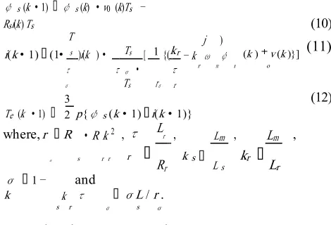
Predictive stator flux, stator current and torque in the next (k+1)th sampling time instant become,
ψs (k 1) ψs (k) v0 (k)Ts −
Rsi(k)Ts (10)
i(k 1)(1
T
s )i(k ) Ts [ 1{(kr− k
r j ω m ) ψ r
(k ) v (k )}] (11)
τ
σ
τ
σ
Ts rσ
τ
r
o
Te (k 1)
3
p{ψs(k 1) i(k 1)}
(12)
2
where, r R
R k 2 ,τ
r
Lr
,
k s
Lm
,
kr Lm ,
σ s r r
Rr L s Lr
σ 1 −
k s k r and τ σ
σL / r .
s σ
B. Delay time compensation
base quality capacity, and connected it in the following (k+1)th testing time incitation. Accordingly, one examining time is accessible to repay the time delay created by the processor.
C. Determination of the predictive model for
(k+2)th sampling time instant
Applying the Euler’s Approximation, similarly, for the second next (k+2)th sampling time instant,
the predictive stator flux, stator current, and torque become as follows:
ψs (k 2) ψs (k 1) vo (k)Ts−Rsi(k 1)Ts (13)
i(k 2)(1 Ts)i(k 1) Ts [ 1{(kr− k
r jωm)ψ r(k 1) vo(k )}]
τσ
Ts Rσ
τ
σ τ r (14)
3 (15)
Te (k 2)
p{ψs (k 2) i(k 2)}
2
D. Quality function
The quality function in the predictive control of IM with delay compensation is presented as below,
g IM(k 2) Te(k 2)− Tref
λ
*
ψs (k 2) −ψ
ref (16)
where, Tref , ψref are the reference torque and
reference flux, respectively. λ , is the weighting factor, and represent the flux control has a priority control rather than the torque control.
E. Delay time compensated predictive control scheme
The predictive control scheme and algorithm for induction motor control are presented in Figs. 2(a) and 2(b), respectively. The predictive controller satisfies the following steps:
• First: stator voltage, vo (k) ; stator current,
i(k); and speed, ωm (k) of induction motor
are measured in the k th sampling time
instant.
(a)
(b)
Fig. 2. (a) Predictive control scheme and (b) algorithm
• Second: stator reference flux (ψref) and
reference speed (ωref ) are known values.
torque (Tref ).
• Third: estimation of the stator and rotor flux. • Fourth: predictive torque Te (k
predictive stator flux ψs (k
in the next sampling time period (k+1)th
based on measured variables. And, this predictive torque and flux are used to predict the (k+2)th predictions of the same variables
for all eight possible switching vectors. • Fifth: the (k+2)th predictive values are
compared with their respective references, and determine the quality functions for all the possible switching states.
• Lastly, the optimum switching vector corresponds to the minimum cost function is selected for the next sampling time actuation.
IV. SIMULATION RESULTS
The proposed control technique is confirmed in MATLAB Simulink and in addition test acceptance with DS1104 R&D Controller at various velocity locales to legitimize the execution of the proposed control plan. The parameters utilized as a part of the recreation and experimentation are given in Table I
A. Simulation Results
The Figs. 3 and 4 speak to the aftereffects of IM control connected with model predictive control (MPC) technique at fast and low speed areas, separately. In both reenactments, the motor begin at 0.01s with the reference torque of 6 Nm in Figs. 3(a) and 4(a). The predictive torque takes after the reference torque with high following reaction in both checks. In Figs. 3(a) and 4(a), when the motor get its reference rapid of 125 rad/s, and 37.125 rad/s, individually, the predictive torque gets to be at least, and takes after the reference torque, precisely high torque of 6 Nm in both the examination.
Additionally, the predictive stator flux tracks the reference flux extremely well, and keep up the size of 1.0 Wb all through the recreation time in Figs. 3(a) and 4(a). The Figs. 3(b) and 4(b) demonstrate the αβ − components of the stator current of IM comparing to reference changes in the reenactments which demonstrate an exceptionally reassuring conduct with the stage removal of 90o between the two components at forward and reverse speed areas.
Simulation without controller:- High speed
Torque :-
Inverter :-
Low speed:-
Inverter :-
Simulation with controller: results High speed:-
To rque:
C urrent:
Flux:
Inverter output:-
Fo r low speed:-
To rque:-
C urrents:-
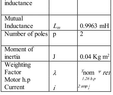
TABLE I: SIMULATION AND EXPERIMENTAL PARAMETERS
Description Variables Values Sampling time Ts 25 µs
DC voltage Vdc 500 V
Supply
frequency f s 50 Hz
Reference speed ωref
125 rad/s and 37.175 rad/s Nominal torque Tnom 6 Nm
Reference Flux ψ ref 1.0 Wb
Stator resistance Rs 21 Ω
Stator
inductance L s 1.053 mH
Rotor resistance Rr 22.63 Ω
Rotor L 1.081 mH
inductance Mutual
Inductance Lm 0.9963 mH
Number of poles p 2 Moment of
inertia J 0.04 Kg m2
Weighting
Factor λ Tnom ψref
Motor h.p 1.26 h.p
Current i 2 amp
V. CONCLUSION
The reproduction demonstrate that the predictive control is a promising control instrument that is vigorous and effective to control the force converters and electrical machine drives. The proposed delay time repaid model predictive control technique uses the discrete and inductive nature of the force converter and impelling engine load. In this control, the long expectation skyline, i.e, the second next (k+2)th predictive variables are anticipated, and contrasted with the references with decide the quality capacities for all the conceivable eight exchanging vectors of the converter to beat the unavoidable control delay.
REFERENCES
[1] Y.-S. Lai, J.-C. Lin, and J. J. Wang, "Direct torque control induction motor drives with self-commissioning based on
[2] Taguchi methodology," IEEE Transaction on Power Electronics, vol. 15, pp. 1065-1071, 2000.
[3] K.-B. Lee and F. Blaabjerg, "Sensorless DTC-SVM for induction motor driven by a matrix converter using a parameter estimation strategy," IEEE Transactions on
[3] Industrial Electronics, vol. 55, pp. 512-521, 2008. S. Muslem Uddin, S. Mekhilef, M. Rivera, and J. Rodriguez, "A FCS-MPC of an induction motor fed by indirect matrix converter with unity power factor control," in
Proc. 8th IEEE Conference on Industrial Electronics and Applications (ICIEA)
[4] D. E. Quevedo, R. P. Aguilera, M. A. Pérez, P. Cortés, and R. Lizana, "Model predictive control of an AFE rectifier with dynamic references," IEEE Transactions on Power Electronics, vol. 27, pp. 3128-3136, 2012.
[5] M. Uddin, S. Mekhilef, M. Mubin, M. Rivera, and J. Rodriguez, "Model Predictive Torque Ripple Reduction with Weighting Factor Optimization Fed by an Indirect Matrix Converter,"
Electric Power Components and Systems, vol. 42, pp. 1-11,2014.
[6] M. Uddin, S. Mekhilef, M. Rivera, and J. Rodriguez, "Predictive Indirect Matrix Converter Fed Torque Ripple Minimization with Weighting Factor Optimization," In Proc. of International Power Electronics Conference (IPEC), pp. 3574-3581, 2014.
[7] M. Rivera, C. Rojas, A. Wilson, J. Rodriguez, J. Espinoza, C. Baier, and J. Muñoz, "Review of predictive control methods to improve the input current of an indirect matrix converter,"
IETPower Electronics, pp. 1-9, 2013.
[8] S. Vazquez, J. Leon, L. Franquelo, J. Rodriguez, H. Young, A. Marquez, and P. Zanchetta, "Model Predictive Control: A Review of Its Applications in Power Electronics," IEEE Industrial Electronics Magazine, vol. 8, pp. 16-31, 2014.