ISSN 2348 – 7968
Modeling and Simulation of Solid Oxide Fuel Cell System
Selvaraj.V1, Sivakumar.R1 and Raja Sekaran.G1
1
Department of Electronics and Instrumentation Engineering, St. Joseph’s College of Engineering, Chennai, Tamilnadu, India
Abstract
Fuel cell technology is a relatively new energy-saving technology that has the potential to compete with the conventional existing generation facilities. Among the various onsite generation or distributed generation or localized generation technologies available, fuel cells are being used as a potential source of electricity because they have no geographic limitations and can be placed anywhere. Fuel cells have number of benefits which make them superior than other technologies. The continuous power supply to the load as per the demand is provided by the integration of the fuel cell system. In this paper, the characteristic of Solid Oxide Fuel Cell (SOFC) is studied and model has been developed based on the physical and chemical equations. In this work, the steady state and dynamical operation of SOFC technologies has been analysed.
Keywords: SOFC, Physical and chemical equations, Steady State, Dynamic Operation
1. INTRODUCTION
The power is generated by the fuel cells through the electrochemical reaction between hydrogen and oxygen. The conversion efficiency is high and leaves only water and heat as the by-products, which is the main motivation for the increasing the interest in this technology [6]. Fuel Cells offer lower emission and higher efficiency than Diesel Engine but are likely to be expensive for many applications. The first fuel cell unit was discovered and developed by SirWilliam Grove 1842 [12] with the use of four primitive cells utilizing hydrogen and oxygen. However, it was not used practically until the 1960’s when NASA demonstrated a potential fuel cell application. After such demonstrations, commercial companies became interested in this technology because of its power quality, high efficiency, modularity and the environmental benefits. Fuel cells could potentially replace the internal combustion engine and many other energy generation devices used today. Reduced emissions of greenhouse gases and increased efficiency are two of the major reasons that fuel cells are being seriously researched as a replacement to the internal combustion engine.
A fuel cell (FC) is an electrochemical energy conversion system, where chemical energy is directly converted into the electrical energy and heat. The main advantages of this technology are high efficiency almost at
partial load, low emissions, and noiselessness (due to nonexistence of moving parts), and free adjustable ratio (50 kW to 3 MW) of electric and heat generation. The basic structure of fuel cells consists of a pair of electrodes, one positive and negative, and an electrolyte. The fuel used in the fuel cell is usually hydrogen, but fuel cell also requires oxygen. The hydrogen is supplied to the anode where the fuel is oxidized, liberates the electrons, which directed through the external circuit. At the cathode, the oxidant is reduced, consuming electrons from the external circuit. Ions are traveled through the electrolyte to balance the flow of electrons through the external circuit. The anode-cathode reactions and the composition and direction of the flow of the mobile ion vary with the type of fuel cell. All fuel cells generate a direct current only, the voltage depending on cell voltage and the number of cells connected in series. Furthermore, the voltage varies with the load and also to some extent with time as the fuel cell stack ages. To obtain AC current, the fuel cell equipment should have power conditioning equipment such as inverter to handle DC to AC conversion and current, voltage, and frequency control. Fuel cells have high reliability as the number of moving parts is low. It consists of auxiliary equipment such as fans and pumps. The target for life length of fuel cells is usually given as 40000 h for the stack and at least twice the number of hours for the system. This target has been reached for a minimum number of fuel cells but in general it still remains to be proven.
2. SOLID OXIDE FUEL CELL
ISSN 2348 – 7968
whose function is to prevent electrons from crossing over while allowing passage to the charged oxygen ions.
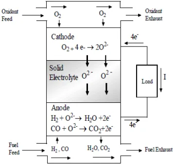
Figure 1 Basic Electrochemistry of an SOFC
The reduction reaction is carried out at the cathode where molecular oxygen reacts with the electrons supplied from external circuit to the produce oxide ions. The oxygen ions travel through the solid electrolyte to anode. In the anode side, they combine with the hydrogen molecule to produce the water, carbon-di-oxide and electrons. The electrons flow through the externally connected circuit to reach the cathode and producing electrical energy in the process. Water is produced by the recombination of oxygen ions and electrons with hydrogen at the anode, as opposed to PEMFCs where water is produced at the cathode. Under operation, either an oxygen ion-conducting electrolyte or a proton conducting electrolyte can be used by the SOFC. Here the SOFC with the oxygen ion-conducting electrolyte (SOFC-O2-) has been considered rather than with proton-conducting electrolyte (SOFC-H+) as Solid Oxide fuel cells are based on concept of an oxygen ion conducting electrolyte. The high temperature operation of SOFC enables it to work with hydrogen as well as hydrocarbon-based gases as fuel. In addition, SOFCs has the high tolerance to fuel impurities such as natural gas. They permit internal reforming, and also use less expensive catalysts for the dissociation of the oxidant. The chemical reactions placed inside the SOFC which are directly involved in the production of electricity are as follows.
At anode (fuel electrode):
H2 + O2- = H2O + 2e- (1)
CO + O2- = CO2 + 2e- (2)
At cathode (air electrode):
O + 4e- = 2O2- (3)
Overall cell reaction:
H2 + ½ O2 = H2O (4)
3. MODELING OF SOFC
Solid Oxide Fuel Cells (SOFC) are particularly attractive because they are the most efficient in terms of fuel input to electricity output. This technology is best applicable in the MG. The high operating temperature produces heat suited well to cogeneration applications. SOFC do not contain noble metals and do not utilize liquid electrolytes which can cause problems and be expensive [10]. The stack model will be based on the following assumptions.
• The gases are ideal.
• The stack is fed with hydrogen and air. If the natural gas is used as the fuel, the dynamics of the fuel processor must be added in the model, upstream of the hydrogen inlet, as a first-order transfer function [2]. The transfer function gain should reflect the changes in composition occurring during the process.
• The channels that transport the gases along the two electrodes have a fixed volume, but their lengths are small, so that it is only necessary to define one single pressure value in their interior. • The exhaust of each channel is via a single
orifice. The ratio of pressures between the interior and exterior of the channel is large enough to consider that the orifice is choked.
• The temperature is stable at all times.
• The only source of losses is ohmic, as the working conditions of interest are not close to the upper and lower extremes of current.
• The Nernst equation can be applied.
By Nernst’s equation output fuel cell dc voltage Vfc across stack of the fuel cell [5] at current Ifc is given by the
fc 5 . 0 0
0 ln -rI
2
2 2 2
+ =
O H
O H fc
P P P
F RT E N
V (5)
Where,
Vfc-Fuel cell stack voltage(V), N0-Number of cells in stack,
E0-Standard reversible cell potential(V), Ifc-Stack Current(A)
r-Internal resistance of the stack(Ω), R-Universal gas constant(J/molK),
ISSN 2348 – 7968
The expression for partial pressure of hydrogen as [5]
(
r fc)
in H H
H
H q K I
s K P 2 1 1 2 2 2
2 = +τ −
(6)
Where,
2
H
τ
is the value of system pole associated with the hydrogen flow, expressed in seconds and is given asRT K V H an H 2 2 = τ
The partial pressure for the reactant, oxygen and product, water can be expressed as follows,
(
r fc)
inO O
O
O q K I
s K P − + = 2 2 2 2 1 1
τ
(7)
(
r fc)
O H
O H O
H
K
I
s
K
P
2
1
1
2 22
=
+
τ
(8)
Where
O H
K
2 -Valve molar constant for water [kmol/(s atm)]
2
H
K
-Valve molar constant for hydrogen [kmol/(s atm)]2
Ko
-Valve molar constant for oxygen [kmol/(s atm)] Fuel utilization is the ratio between the fuel flow that reacts and the input fuel flow. Hence, we havein H r H f q q U 2 2
=
(9)
It has been shown that the fuel utilization ranging from 0.8 to 0.9 provides the better performance and prevents overused and underused fuel conditions. Considering the above specified fuel conditions, Uf > 0.9 can cause permanent damage to the cell because of fuel starvation and Uf < 0.7leads to higher cell voltage rapidly. For the definite hydrogen input flow, the demand current of fuel cell system can be limited in the range given as:
r in H in r in H K q I K q 2 9 . 0 2 8 . 0 2
2 ≤ ≤
(10)
The optimum utilization factor assumed for this model is 0.85[17]. The fuel utilization can be set at this value by regulating the input fuel flow depending on the real output current recorded in the fuel cell system. Therefore, the value of fuel input flow, depending on fuel cell output current is given as
85 . 0 2 2 fc r in H I K
q =
(11)
From the overall fuel cell reaction (4), the stoichiometric ratio of hydrogen to oxygen is 2 to 1. Oxygen excess is always taken to let hydrogen react with the oxygen more completely. Their simulation in fuel cell system shows that rH-O should be kept around 1.145 in order to keep the fuel cell pressure difference below 4 kPa under normal operation.
The chemical reaction is modeled as a first-order transfer function with a 5S time constant because of the fuel processor is usually slow as it is associated with the time to change the chemical reaction parameters after a change in flow reactions. The electrical response time in the fuel cells is generally fast and mainly associated with the speed at which the chemical reaction is capable of restoring the charge that has been drained by the load. This is also modeled as a first-order transfer function but with a 0.8 s time constant.
Based on [8] and the above discussions, the SOFC system dynamic model which is proposed by [14] is summarized in (11) and (12).
= > → −− − − − > → −− − − − = − − − otherwise V P I K U q I if K U q K U q I if K U q I fc ref r in H r in H r in H r in H ref , 2 , 2 2 , 2 min min max max 2 2 2 2 (11)
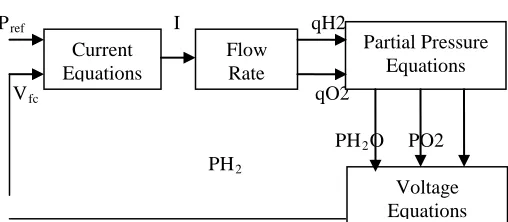
The block diagram of dynamic model of a SOFC is shown in Figure 2.The different model parameters such as maximum fuel utilization, minimum fuel utilization, optimum fuel utilization fuel system response time, and electrical response time and so on as mentioned in Table 1. The power produced by the fuel cell is then given by the following relation:
Pfc = Vfc Ifc (12)
Pref I qH2
Vfc qO2
PH2O PO2 PH2
Figure 2 Block diagram for dynamic model of SOFC
ISSN 2348 – 7968
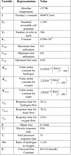
Table 1 Parameters of the SOFC
Variable Representation Value
T Absolute
temperature
1273K
F Faraday’s constant 96487C/mol
E0 Standard
reversible cell potential
1.18V
No Number of cells in stack
384
Kr Constant 0.996×10⁻⁶
Umax Maximum fuel utilization
0.9
Umin Minimum fuel utilization
0.8
Uopt Optimum fuel ratio 0.85
2
H
K
Value molarconstant for hydrogen
Χ −
atm s Kmol
04 10 43 . 8
2
O
K
Value molarconstant for oxygen
Χ
−atm
s
Kmol
0310
52
.
2
O H
K
2
Value molar constant for
water
Χ
−atm
s
Kmol
0410
81
.
2
2
H
τ
Response time for hydrogen flow26.1s
O H2
τ
Response time for water flow78.3s
2
O
τ
Response time for oxygen flow2.91s
R Ohmic loss 0.126Ω
Te Electric response time
0.8s
Tf Fuel processor response time
5s
rHo Ratio of hydrogen to oxygen
1.145
R Universal Gas Constant
8314 J/(kmolk)
4. SIMULATION RESULTS
It is assumed that the stand-alone SOFC system is operating with constant rated voltage 333.8 Volts and power demand 70 kW. All parameters of the system are the same as in Table 1.
2450 2500 2550 2600 2650 2700 2750 2800 2850 2900 6.5
7 7.5 8 8.5 9 9.5 10 10.5x 10
4
Time(Sec)
Po
w
e
r(W
a
tts
) Power Demand
Real Output Power
Figure 3 Response of SOFC when increasing power demand from 70KW to 100KW
At t = 2500 sec, there is a step increase of the power demand from 70 kW to 100 kW. Figure 3 shows the dynamic response of this system. Figure 4 shows the dynamic response of the SOFC when there is a decreasing in power demand from 70 kW to 40 kW.
24503 2500 2550 2600 2650 2700 2750 2800 2850 4
5 6 7 8x 10
4
Time(Sec)
Po
w
e
r(W
a
tts
)
Power Demand Real Output Power
Figure 4 Response of SOFC when decreasing power demand from 70KW to 40KW
Results show that the SOFC has some slow dynamic response, so that using SOFC alone may be not suitable for systems that need a fast dynamic response.
ISSN 2348 – 7968
2200 2300 2400 2500 2600 2700 2800 2900 3000 -0.5
0 0.5 1 1.5 2 2.5 3 3.5
Time(Sec)
D
if
fer
enc
e P
res
s
ur
e(
k
P
a)
Figure 5 Response of pressure difference between hydrogen and oxygen
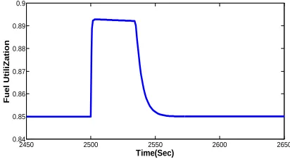
In Figure 6 the fuel utilization response is presented, due to increase in the power demand, the fuel utilization increases to the maximum fuel utilization Umax in about 2500 s. After staying at Umax for about 25 s, it decreases to optimal fuel utilization Uopt.
2450 2500 2550 2600 2650
0.84 0.85 0.86 0.87 0.88 0.89 0.9
Time(Sec)
Fue
l U
tiliZa
tion
Figure 6 Response of Fuel Utilization
5. CONCLUSIONS
Modeling and simulation study of a SOFC power system is investigated in this paper. The response of the system to step changes in load demand are presented along with the analysis of the simulated results. A validated SOFC dynamic model is used to model the fuel cell system. The model can be used in future applications for the analysis of hybrid power systems. A hybrid power system consists of a combination of two or more power generation technologies to do the best use of their operating characteristics and to obtain higher efficiencies than those can be obtained from a single power source.
REFERENCES
[1] Caisheng wang and M.Hashem Nehrir “A Physically Based Dynamic Model for Solid Oxide Fuel Cells”, IEEE Transactions on Energy Conversion. Volume 19, No.2, June 2004.
[2] Ellis, M.W., Von Spakovsky, M.R., and Nelson, D.J., “Fuel cell systems: efficient, flexible energy conversion for the 21st century”, In Proceedings of the IEEE, volume 89, pages 1808 – 1818, Dec. 2001.
[3] James Larminie and Andrew Dicks “Fuel Cell Systems Explained”, Second Edition, John Wiley & Sons Ltd, The Atrium, Southern Gate, Chichester, January 2003.
[4] Kourosh Sedghisigarchi and Ali Feliachi “Dynamic and Transient Analysis of Power Distribution Systems with Fuel Cells – Part I: Fuel Cell Dynamic Model”, IEEE Transactions on Energy Conversion. Volume 19, No.2, June 2004.
[5] Li, Y.H., Choi, S.S., and Rajakaruna, S., “An Analysis of the Control and Operation of a Solid Oxide Fuel Cell Power Plant in an Isolated System”, IEEE Transactions on Energy Conversion, Volume 20, No.2, June 2005.
[6] Morgantown, W., “Fuel Cell Handbook”, 6th Edition, EG&G Technical Services, Virginia, November 2002. [Online]. Available:
http://www.rwth-aachen.de/lbz/linksframe.html.
[7]Padulles, J., Ault G.W., and McDonald, J.R., “An integrated SOFC plant dynamic model for power systems simulation”, Journal of Power Sources 86, Pages 495–500, October 2000.
[8] Padulles, J., Ault, G.W., Smith, C.A., and McDonald, J.R., “Fuel cell plant dynamic modelling for power systems simulation”, In Proceedings of 3dth universities power engineering conference, volume 34, pages 21–25, 1999. [9]Prema Kumar, N., Nirmala Kumari, K., and Rosalina, K.M., “Modeling Design of Solid Oxide Fuel Cell Power System for Distributed Generation Applications”, International Journal of Advanced Research in Computer Engineering & Technology (IJARCET) Volume 1, Issue 9, November 2012.
[10] Sakhare, A.R., Davari, A., and Feliachi, A., “Control of stand-alone solid oxide fuel cell using fuzzy logic”, In Proceedings of the 35th Southeastern Symposium on System Theory, 2003., pages 473 – 476, 16-18 March. 2003.
[11] Salam, A.A., Hannan, M.A., and Mohamed, A., “Dynamic Modeling and Simulation of Solid Oxide Fuel Cell System”, 2nd IEEE International Conference on Power and Energy (PECon 08), December 1-3, 2008, Johor Baharu, Malaysia.
[12] Smith, J.A., Nehrir, M.H., Gerez, V., and Shaw, S.R., “A broad look at the workings, types, and applications of fuel cells”, In Power Engineering Society Summer Meeting, volume 1, pages 70–75, Chicago, USA, July 2002.
[13] Vera, D., and Jurado, F., “Development of Solid Oxide Fuel Cell Based System in Stand Alone Mode”, The Open Renewable Energy Journal, Volume 2, Pages 38-42, January 2009.