1
Membrane Module Design and Dynamic Shear-Induced Techniques
to Enhance Liquid Separation by Hollow Fiber Modules: A Review
Xing Yang1, Rong Wang1,*, Anthony G. Fane1, Chuyang Y.Tang1, I.G. Wenten2
1. Singapore Membrane Technology Centre;
School of Civil & Environmental Engineering;
Nanyang Technological University, Singapore 639798
2. Institute of Technology Bandung, Indonesia
* Corresponding author
Email: [email protected]
Tel: (65) 6790 5327
2
Abstract
Membrane-based separation processes have found numerous applications in various
industries over the past decades. However, higher energy consumption, lower productivity and
shorter membrane lifespan due to polarization and membrane fouling continue to present severe
technical challenges to membrane-based separation. Improved membrane module design and
novel hydrodynamics offer strategies to address these challenges.
This review focuses on hollow fiber membrane modules which are well-suited to membrane
contactor separation processes. Attempts to improve membrane module design should begin with
a better understanding of the mass transfer in the hollow fiber module, therefore this review
provides a summary of prior studies on the mass transfer models related to both the shell-side
and tube-side fluid dynamics. Based on the mass transfer analysis, two types of technique to
enhance hollow fiber membrane module performance are discussed: (1) passive enhancement
techniques that involve the design and fabrication of effective modules with optimized flow
geometry; or (2) active enhancement techniques that uses external energy to induce a high shear
regime to suppress the undesirable fouling and concentration polarization phenomena. This
review covers the progress over the past five years on the most commonly proposed techniques
such as bubbling, vibrations and ultrasound.
Both enhancement modes have their advantages and drawbacks. Generally, the passive
enhancement techniques offer modest improvement of the system performance, while the active
techniques, including bubbling, vibrating and ultrasound, are capable of providing as high as
315 times enhancement of the permeation flux. Fundamentally, the objectives of module design
3
and module production cost) and the maximization of the system performance through
optimizing the flow geometry and operating conditions of the module, scale-up potential and
expansion of niche applications. It is expected that this review can provide inspiration for novel
module development.
4
1. Introduction
Membrane-based separation processes have found many applications in fields such as water,
energy, chemical, petro-chemical and pharmaceutical industries. This growth has been primarily
due to two developments: firstly, the ability to produce high permeability and essentially
defect-free membranes on a large scale; and secondly, the ability to assemble these membranes into
compact, efficient and economical membrane modules with a high membrane surface area [1-3].
Nevertheless, there are still several limitations hindering the application of membrane-based
processes, including flux decline, concentration polarization and membrane fouling. These
limitations can reduce productivity, increase energy consumption and shorten membrane lifespan.
A sustainable flux depends not only on membrane permeation properties, but also on the fluid
hydrodynamics within the membrane module. In recent decades, numerous attempts have been
made to design and fabricate effective membrane modules with optimized geometries and/or
shear-induced accessories to enhance permeation and suppress undesirable polarization and
membrane fouling [4-9].
The performance improvement methods can be classified into two categories: passive
enhancement techniques and active enhancement techniques. The passive techniques include
modifying membrane layout or introducing spacers or baffles into the membrane modules to
alter the flow geometries, by inducing secondary flows or eddies adjacent to the membrane
or/and creating significant flow instabilities. The active techniques utilize external energy to
enhance the relative motion between the fluid and the membrane. The induced high shear rate
5
There is considerable evidence that properly designed and fabricated membrane modules
can improve the fluid hydrodynamic conditions and enhance overall system performance
dramatically. However, despite its importance, membrane module design and fabrication have
received less attention than membrane materials and membrane process development. The
literature in this field is relatively sparse in comparison with the rapidly increased amount of
literature in other membrane–related areas. The main reason is probably due to the fact that
module technology has been developed commercially in the form of patents which are treated as
proprietary knowledge by industry.
This paper starts by summarizing the basic types of membrane module used for aqueous
separations with a focus on hollow fiber modules and related mass transfer models. Then we
discuss passive process enhancement techniques involving module/fiber configuration designs
and active process enhancement techniques involving shear enhanced aids (vibrations/oscillation,
bubbles and ultrasound etc) [10-12]. The focus is given to the latest developments in hollow fiber
module design concepts and principles of mass transfer enhancement, because hollow fiber
membrane technology is an attractive platform for many engineering processes. Moreover, by
analyzing the working principle of each enhancement mode for practical applications, their
benefits, limitations and technical requirements are addressed in terms of economic
considerations (fabrication cost and complexity, energy demand) and processing engineering
(scale-up potential and niche applications). It is hoped that this review can provide insights and
inspire novel module design to enhance system performance of membrane-based processes for
liquid separations.
6
Industrial membrane separation requires large areas of membrane surface to be
economically and effectively packaged. These packages are called membrane modules. Effective
module design is one of the critical achievements that has led to the commercialization of
membrane–based separation units [2].
Generally, there are four basic types of module: plate-and-frame, spiral wound, tubular and
hollow fiber modules. The earliest module designs were based on simple filters and consisted of
flat sheets of membranes confined in a filter press called “plate-and-frame” modules. Due to its
simplicity, these plate-and-frame modules have been widely used in lab-scale and industrial
applications. Although each type of membrane module configurations has its own pros and cons,
hollow fiber modules have received the most attention because of their unique characteristics of
self-support, high membrane packing density and high contact surface to volume ratio. The
surface to volume ratio (m2/m3) is typically 350–500 for plate-and-frame modules, and 650–800 for spiral wound modules. In contrast, hollow fiber membrane modules may have the ratio as
high as 7000–13000. In addition to this, hollow fibers have the greatest potential to be arrayed in
different forms for various applications [13]. The most common form is the conventional
7 (a)
(b)
Fig. 1. A conventional parallel flow hollow fiber module
(a) tube-feed; (b) shell-feed with dead end (redrawn from [13])
Hollow fiber modules typically operate using one of two flow patterns: tube-side (or
lumen-side) feeding or shell-side feeding. The former is commonly used in biotechnology applications
and the latter for water applications. In some cases, such as membrane contactors, both tube and
shell sides require controlled flows. Hydrodynamic challenges with the shell-side flow pattern of
hollow fiber membrane modules include: bypassing, channeling and dead zones, which result in
a loss in separation efficiency. While channeling may not be apparent in small scale bench tests,
it becomes a serious concern in full scale applications [13]. This concern has led to major efforts
in improving hydrodynamic conditions to overcome this problem, which is discussed in detail in
Section 4.1 of this paper.
3. Mass transfer analysis for hollow fiber module design
Fundamentally, in all membrane separation processes, a molecule or particle is transported
8
flow will occur through the membrane after the establishment of a steady state. For a general
liquid-liquid membrane separation process, the overall flux Js of the solute to be removed or
retained can be expressed by a proportionality relationship [14]:
s
J k F (1)
where F is the overall driving force of the process, and the proportionality factor k is the
overall mass transfer coefficient, which determines how fast the component is transported
through the membrane, or in other words, k is a measure of the resistance exerted by the whole
transport process.
In a hollow fiber module, the transport of this component will follow three basic steps: from
bulk feed to the membrane surface, across membrane and from the other surface of the
membrane to the bulk permeate. By assuming the feed is flowing through the shell-side, k can
be expressed based on the resistance-in-series model [15]:
1 1 1 1 t in
m tube shell t out
d
k k k k (d ) (2)
where km is the membrane mass transfer coefficient; kshell, the mass transfer coefficient through
the boundary layer on the feed side (most commonly used correlations are shown in Table 1) and
tube
k , the mass transfer coefficient through the boundary layer in the permeate side; dt in and
t out
d are the inner and outer diameters of the fiber, respectively. All mass transfer coefficients
here are calculated based on the inner membrane surface of the fiber. It should be noted that
these theories which are involved in solute transport are not applicable to some special processes
9
With rapid advancement of membrane science, currently available membranes used in many
applications are so effective that the separation process is limited mainly by the mass transfer
rate to the bulk-membrane interface rather than through the membrane itself [7]. To further
interpret the mass transfer occurring in fluids, it is conventional to correlate parameters in a
dimensionless form, such as the Graetz number (Gz), Schmidt number (Sc) and Sherwood
number (Sh). Gz is a dimensionless duct length, which can be expressed as the product of three
dimensionless groups, as shown in Eq. (3). [16]
h d
Gz Re Sc
L
(3)
where Re is the Reynolds number, dh is the hydraulic diameter of the flowing channels in the
shell-side, L is the effective length of the module. Sh is the most common term by which mass
transfer is described. It is defined as the ratio of convection to diffusion and is dependent on the
shape of the duct and its dimension, as indicated by Eq. (4)
( )
h k d
Sh f Gz
D
(4)
where D is the diffusion coefficient of the solute in the feed side solution, Generally the mass
transfer correlations can be expressed as [17]:
(dh)
Sh aRe Sc
L
(5)
where a is a function of module geometry, , and are constants determined experimentally.
Sh can be viewed as the ratio of the characteristic dimension of the flow path to the boundary
layer thickness on the membrane surface. In laminar flow, some applicable correlations contain
an additional factor involving the characteristic dimension divided by the length of the flow path
10
Among various membrane processes involving liquid separation using membranes, for
pressure-driven systems (e.g. reverse osmosis (RO), microfiltration (MF) & ultrafiltration (UF)),
only the feed side (shell-side feeding pattern is assumed) may be subject to concentration
polarization, which describes the phenomena of concentration build-up within the boundary layer
near the membrane surface, due to the poor hydrodynamics and hence the low mass transfer
coefficient [7]; while for most concentration-driven systems (e.g. membrane contactors), both
tube and shell-side flows may have great impact on the overall module performance (e.g.
artificial kidney, blood oxygenator, membrane distillation processes, etc) [18]. In some cases,
even the membranes may play an important role in the overall mass transfer resistance [19].
Therefore, to design a well-performed hollow fiber module requires not only a better
understanding of fluid dynamics on the shell-side, but also the flow on the tube-side and the
mass transfer resistance across the membrane. A comprehensive summary of prior development
of mass transfer models are provided in the following section.
3.1 Mass transfer in shell-side
Although many studies have focused on either empirical or fundamental approaches to
describe the shell-side mass transfer coefficient in conventional cross-flow hollow fiber modules
[20-24], none of them are presented in a general form which can be applied to all membrane
processes involved liquid phases. Most of the studies on mass transfer inside hollow fiber
modules are based on membrane contactors, and the blood oxygenator and CO2 contactor are the most adopted processes to study the shell-side fluid behavior due to their simplicity. However,
more and more rigorous engineering approaches have been developed by many researchers in
11
transfer was proposed by Lipnizki and Field [21]. This approach covers a wide range of packing
densities, the effect of flow mal-distribution, both laminar and turbulent flow, the entrance
effects, and the development of both the hydraulic and concentration profiles. It can be
interpreted as:
1. Laminar flow (Re<2300)
(i) Both hydrodynamic and concentration profiles are fully developed,
0.4 1 3.66 1.2
Sh (6)
where is the packing density.
(ii) A developing concentration profile with full hydrodynamic development, and the entrance
effect is taken into account:
0.25 0.33
2 1.615(1 0.14 ) ( )
h Re Sc d Sh
L
(7)
(iii) Both profiles are developing, the entrance effects are considered:
1/6 0.5 3 2 ( ) ( ) 1 22 h Re Sc d Sh
Sc L
(8)
if there is a need to include entrance effects even when the fluid leaves the module with fully
developed profiles. Sh1 and Sh2 can be combined to predict the overall average mass transfer coefficient:
3 3 1/3 1 2
( )
Sh Sh Sh (9)
If the fluid leaves the module with fully developed hydrodynamic profile and developing
concentration profile, and entrance regions should be included, the overall average Sh can be
expressed as:
3 3 1/3 2 3
( )
12
Similarly, if the complete range of profile developments is considered, Sh for the whole
range can be calculated by:
3 3 3 1/3 1 2 3
( )
Sh Sh Sh Sh (11)
2. Turbulent flow (2300<Re≤106)
The mass transfer correlation can be derived based on a heat transfer analogy for flow
through an annulus by Stephan [25], with Sc >> 0.0454:
0.225 0.8 0.33
0.021
Sh Re Sc (12)
As mentioned above, most of the empirical correlations developed by different researchers
are based on specific studies of various systems and operating conditions, and most importantly,
some influential factors such as the entrance effects, the development state of hydrodynamic and
concentration profiles, the impact of packing density and mal-distribution phenomenon, and fiber
polydispersity are neglected. To make the model more comprehensive, Lipnizki and Field [21]
incorporated the effect of packing density and mal-distribution into the hydraulic diameter,
divided the hollow fiber module into segments and proposed the prediction of average Sh via a
sum of the local Shk:
1
1
( , )
n
av k k k k
k
Sh A Sh Re
A
(13)where k refers to the segment. However, the fiber polydispersity is not considered in this model.
Hence, there are several new correlations developed by other authors that include random
13
As an important variation developed based on the conventional cross-flow modules,
transverse-flow hollow fiber module has been intensively reported to have larger mass transfer
coefficient, minimal flow channeling and better scale-up characteristics. For more precise
performance prediction, several correlations have been proposed to describe its shell-side mass
transfer [20]. To give an example, one of the shell-side mass transfer correlations has been
developed based on the free surface model [28], which agrees well with the experimental results
of the best-known Liqui-Cel®Extra-Flow module:
0.42 0.33
2.15
Sh Re Sc (14)
Here Re varies from 0.8 to 20. The detail of Liqui-Cel®Extra-Flow module is discussed in Section 4.1.2.
An overview of the historical development of mass transfer correlations, is summarized in
Table 1, which contains some popular models developed by various researchers in recently years.
Although there is already a comprehensive review on hollow fiber membrane contactors by
Gabelman and Hwang in 1999 [20], this paper focuses mainly on the developments since 2000.
In addition, regardless of the increasingly comprehensive models that have been developed, it
should be noted that there is still no universal form which can be applied due to the complexity
of coupling factors. However, a relatively rigorous approach is still feasible to analyze the
hollow fiber module performance and hence help to identify the bottlenecks of module design in
terms of process engineering.
3.2 Mass transfer in the tube-side
For some membrane processes dealing with liquid phases, both shell-side and tube-side flows
14
flow is usually laminar instead of turbulent in the hollow fibers because of the small fiber
diameter and comparatively long length. Any turbulent flow will eventually be reduced to
laminar flow after passing a certain length, due to friction with the membrane wall [29].
Therefore the fluid flowing in the tube-side is generally treated as laminar flow, and the
individual mass transfer coefficient ktube is dependent on the flow velocity. Though there are
several correlations available for the tube-side flow calculation [6, 30], the Lévêque solution (Gz >
4) [31] has been widely accepted in the literature to predict ktube with a reasonable degree of
accuracy:
0.33 0.33 0.33
1.62 ( )
tube t in t in
t
k d d
Sh Re Sc
D L
(15)
0.33 2
1.62 t tube
t in D k
Ld
(16)
where Dt is the diffusion coefficient of the solute in the tube side solution. However, Eq (15)
always overestimates the tube-side mass transfer coefficients when Gz<4. To develop a more
rigorous correlation for hollow fiber systems, Wickramasinghe et al [6] incorporated the
polydispersity of hollow fiber diameters to calculate the average. Their commonly used
correlations for the tube-side mass transfer are also summarized in Table 1.
3.3 Mass transfer across the membrane
As mentioned previously, sometimes the membrane itself may present as the major resistance
in the overall mass transfer, especially in some membrane contactor processes. Here, the local
15
D km
m
(17)
where D is the diffusion coefficient of the solute through the membrane, which can be calculated
by applying the Wilke and Chang method [33]; ε is the membrane porosity, m is the thickness of
membrane wall and τ is tortuosity. Thus, km is merely depending upon the solute diffusivity and
the membrane structure regardless of the operating parameters (It is noted that this solute
transport mechanism across the membrane is not applicable in the MD process because it
16
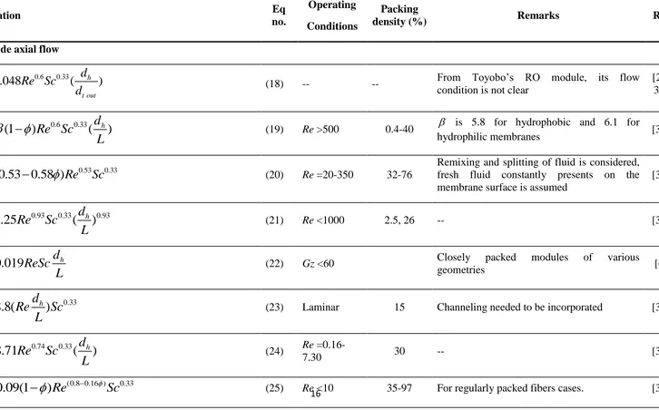
Correlation Eq
no.
Operating Conditions
Packing
density (%) Remarks Ref
Shell-side axial flow
0.6 0.33
0.048
(
h)
t out
d
Sh
Re Sc
d
(18) -- -- From Toyobo’s RO module, its flowcondition is not clear
[24, 34]
0.6 0.33
(1
)
(
d
h)
Sh
Re Sc
L
(19) Re >500 0.4-40 is 5.8 for hydrophobic and 6.1 forhydrophilic membranes [35]
0.53 0.33
(0.53 0.58 )
Sh
Re
Sc
(20) Re =20-350 32-76Remixing and splitting of fluid is considered, fresh fluid constantly presents on the membrane surface is assumed
[36]
0.93 0.33 0.93
1.25
(
d
h)
Sh
Re
Sc
L
(21) Re <1000 2.5, 26 -- [30]0.019
d
hSh
ReSc
L
(22) Gz <60 Closely packed modules of variousgeometries [6]
0.33
8.8(
d
h)
Sh
Re
Sc
L
(23) Laminar 15 Channeling needed to be incorporated [37]0.74 0.33
8.71
(
d
h)
Sh
Re
Sc
L
(24) Re=0.16-7.30 30 -- [38]
(0.8 0.16 ) 0.33
0.09(1
)
Sh
Re
Sc
(25) Re <10 35-97 For regularly packed fibers cases. [39]17
2 0.9 0.33
(0.31
0.34
0.10)
Sh
Re Sc
(26) Re =32-1287 8-70 Flow mal-distribution is taken into account. [40]0.25 3 1.5 0.5 1/3
[4.212
(1 0.14
)
0.302
]
k k k k k
Sh
Gz
Gz
Sc
1
1
(
,
)
n
av k k k k
k
Sh
A Sh Re
A
(27)
(13)
Re <2300
Sc>>1
10-75
Entrance effects, packing density and flow mal-distribution are taken into consideration a hollow fiber module with fully .developed hydrodynamic and developing concentration boundary layer profiles. where Shk and Shov
are the local and overall average Sherwood number, respectively.
[21]
0.225 0.8 0.33
0.021
Sh
Re Sc
(12)2300<Re
≤106
Sc>>1/22
10-75 Derived based on a heat transfer for flow
through an annulus by Stephan [25]
2 2
(4.0108 4.4296 1.5585) 0.33
( 0.4575
0.3993
0.0475)
Sh
Re
Sc
(28) Laminar 30.6-61.2Based on osmotic distillation systems, Re is a function of packing density [22]
0
(0.3 0.14) 0 0
1
(
)
(0.86 0.3 )
h r
d
Sh
ReSc
L
(29)Re =68-1194
Gz=70-5039
20-50
The overall average mass transfer coefficient
r
Sh incorporated the randomcity of fiber/flow distribution, is a dimensionless group presenting the deviation of randomly packed module from uniformly packed one.
18 0 0
0
0 0 2 /( ) 0 0
( ) ( )d d
2
( )d
( ) ( )d d
ln
( ) ( )d d
hk rl v
vf
g r
r
d
Sh
D
l
rg r
r
vf
g r
r
e
vf
g r
r
(30) -- 25-75
For the first time both randomicity of flow distribution and polydispersity of fiber diameter on shell-side mass transfer are considered together.
[23]
Shell-side transverse flow
0.556 0.33
0.575
Sh
Re
Sc
(31) Re <1000 --The analogy of a well-established heat transfer correlation for flow across or transverse to a “staggered bank” of tubes.
[41]
0.8 0.33
0.15
Sh
Re Sc
(32) Re >2.5 --Developed by alternative module geometries, such as cylindrical/helically wound bundles and rectangular-bed configuration.
[6]
0.33
0.12
Sh
ReSc
(33) Re <2.5 --Obtained by the similar configurations with Eq (32) under conditions which may induce uneven flow channels among fibers.
[6]
0.34 0.33
1.38
Sh
Re
Sc
(34) 1<Re <25 70Developed from tightly packed module for O2 or CO2 removal, it was based on heat transfer correlations of single tubes.
[30]
0.4 0.33
0.9
Sh
Re Sc
(35) 1<Re <25 7 Similar to Eq (34), for loosely packed19 0.363 0.33
0.61
Sh
Re
Sc
(36) 0.6<Re <49 0.3 For extremely low packing density cases. [42]0.32 0.33
1.45
Sh
Re
Sc
(37) -- -- Obtained from bubble-free aeration of waterusing transverse flow fiber arrangement. [43]
0.59 0.33
0.24(
d
h)
Sh
Re
Sc
L
(38) -- -- Similar to Eq (37), but used a sealed fiberbundle unconfined in a jet stream instead. [44]
0.42 0.33
2.15
Sh
Re
Sc
(14) 0.8<Re <20 --Developed based on free surface model, which agrees well with the experimental results of the best-known Liqui-Cel®Extra-Flow module
[28]
Tube-side mass transfer
0.33 0.33 0.33
1.62
(
d
t in)
Sh
Re
Sc
L
(15) Gz>4Reasonably accuracy is obtained for mass transfer coefficients estimation when Gz >4 cases, but overestimates when Gz<4.
[31]
0
[1 (18
7]
]
Sh
Sh
Sh Gz
x
(39) --Polydispersity of hollow fiber diameters is incorporated into calculating the average
<Sh>, Sh is for a uniform distribution of fiber radii, x0 represents the deviation divided by the mean.
[6]
0.8 0.33
0.023
Sh
Re Sc
(40) Re>2000 Based on Chilton-Colburn and Deissler analogies.[45, 46]
0.11
(1 0.25 ) 0.33
'
m mw
f
Sc
Sh
Re
Sc
f
Sc
(41)104<Re<105,
Sc>1000 --
Sh, the corrected Sherwood number under conditions of porosity and variable properties,
w
Sc is the corrected Schmidt number on the membrane wall; f is the friction factor and f”
20
Note:
1. This table contains most of the correlations developed after 1999; some earlier models were reviewed by Gabelman and
Hwang [20].
2. Only applications for liquid separation are presented, i.e. gas separation such as adsorption is not included.
3. No chemical reaction is involved in these cases. Some special transverse flow correlations derived from hollow fiber fabric
modules are not presented in this table, they will be given below in the case study.
21
3.4 Basic principles for mass transfer enhancement
The above discussions clearly indicate that the mass transfer in a hollow fiber module is
closely linked to the fluid hydrodynamics and membrane module geometry. Using the membrane
contactor as an example, while the mass transfer through the membrane (km) is independent of
the flow conditions, the mass transfer on shell and tube sides (kshelland ktube) are functions of the
flow conditions and fiber/module geometries. The semi-empirical mass transfer correlations shed
some light on strategies to improve the mass transfer by varying flow conditions and flow
channel design.
On the tube side, Eq (15) is widely used to predict the mass transfer coefficients, where Re
represents the hydrodynamic conditions. However, the predictions by this model slightly
overestimate the experimental data when the flow velocity is very low [20], which may be due to
the non-uniform flow distribution inside the tube. It was found that it is not only related to the
flow velocity (via Re), but may also relate to the effect of fiber length and fiber dimensions. As a
certain degree of uniformity is reached, the mass transfer coefficient ktube can be predicted
reliably. It increases with increasing Re and the diffusivity of the solute of interest [20] , but
decreases with increasing inner diameter and fiber length. Under given conditions, Re seems to
be the dominant factor affecting ktube.
On the other hand, the prediction of the shell-side mass transfer coefficientShshell is more
challenging, since the shell-side geometry and hydrodynamics are more complicated to correlate.
Though there are numerous studies that focus on the shell-side, none are universally applicable
due to the various parameters incorporated in the different models. However, the basic principle
22
increasingly complex form of the model development, it can be concluded that the mass transfer
depends on many factors and their combinations, such as the flow velocity (Re), states of
hydrodynamic/concentration profiles, hydraulic shell diameter and effective length of the module,
entrance effects, fiber polydispersity, packing density, and flow mal-distribution. Furthermore, it
may also be influenced by the interaction between the surface properties of the membrane (i.e.
hydrophobic/hydrophilic character) and the diffusivity of the solute of interest, which is playing
a role in calculating k value [20]. For example, hydrophilic membranes may facilitate the
transport of inorganic solutes, while hydrophobic membranes may transport the organic solutes
preferentially [19, 20].
Clearly, the main objective of improved membrane module design is to enhance the overall
mass transfer. The basic strategies include enhancing the module’s capabilities to create more
eddies or turbulence between fibers, reduce the boundary layer thickness and provide better
mixing. To achieve these goals, various methods and devices have been employed to enhance the
mass transfer inside the module (e.g. the passive enhancement techniques, and active
enhancement techniques). These strategies are reviewed in the following sections (refer to
Section 4.1 and Section 4.2).
4. Process enhancement techniques 4.1 Passive enhancement techniques
The majority of laboratory or industrial scale modules are designed for use with flat sheet
membranes, because the membrane structure is simple and the membrane replacement is easy.
23
much larger surface area per volume. Despite the relatively high fabrication cost, hollow fiber
modules can play an important role and gain better performance to minimize the cost per unit
product volume [47-49].
Most hollow fiber modules are designed for pressure-driven filtration processes rather than
concentration-driven or thermally-driven contactor processes. However, from the process
enhancement point of view, their applications may be potentially extended to suit and improve
other separation processes.
4.1.1 Fabric hollow fiber modules
In the early days, due to limited materials and fabrication methods, membranes themselves
tended to be the controlling resistance in membrane-based separations. With the advancement of
membrane fabrication techniques, it has been possible to produce thinner membranes with higher
permeability. As a result, improving mass transfer of the process has shifted to alternative
geometries that are able to offer better performance than the conventional parallel flows.
It is widely reported that flow mal-distribution in the membrane modules may lead to
decrease module performance and hence a reduction of the average mass transfer coefficient [50].
To overcome the problems of non-uniform fiber spacing in hollow fiber modules, which often
results in a flow mal-distribution, several researchers have introduced fiber-woven fabric into
hollow fiber modules to gain more uniform spacing and baffles to create better mixing [47-49].
The results showed that the shell-side mass transfer coefficient was significantly higher than that
24
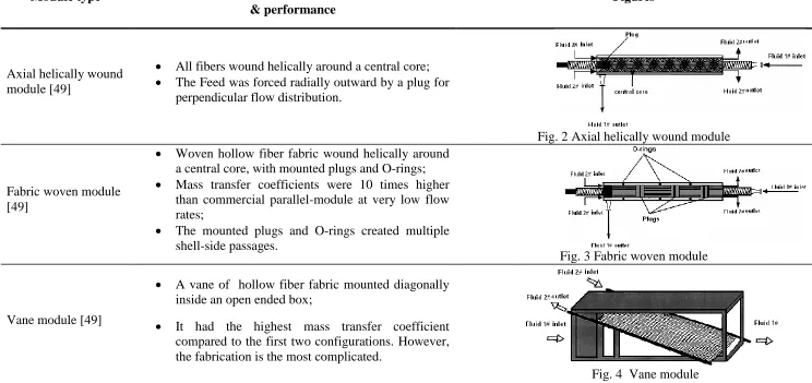
various configurations (Figs.2-6). Their detailed features can be found in an earlier review by
Gabelman and Hwang [20]. In this paper, only a brief summary is given in Table 2.
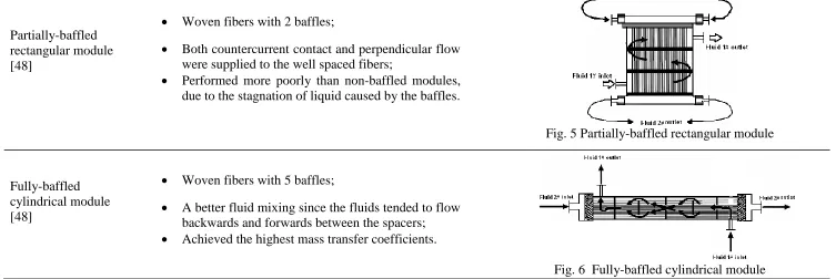
To provide some perspectives on hollow fiber module design, some researchers [48, 49]
correlated Re (flow velocity) and Sh (mass transfer coefficient) with single-fiber modules under
different flow regimes and developed a set of analogous shell-side mass transfer correlations
which showed good agreement with the experimental data (some of these correlations are listed
in Table 1). According to their observations, counter-current flow patterns had much better mass
transfer. Surprisingly, the baffled rectangular module performed more poorly than non-baffled
modules and a cylindrical module with fewer baffles was comparable to a fully-baffled one.
Therefore, it can be seen that baffles can constrain the hydrodynamic conditions in some cases.
These previous studies suggest that turbulence promoters do not always enhance module
efficiency. The effectiveness depends on how the promoters are arranged and how the flow
channels are actually distributed. However, most of the mentioned configurations improve the
fluid distribution and mixing to achieve much higher mass transfer coefficients in both gas and
25
Module type
Key characterisitics & performance
Figures
Axial helically wound module [49]
All fibers wound helically around a central core; The Feed was forced radially outward by a plug for
perpendicular flow distribution.
Fig. 2 Axial helically wound module
Fabric woven module [49]
Woven hollow fiber fabric wound helically around a central core, with mounted plugs and O-rings; Mass transfer coefficients were 10 times higher
than commercial parallel-module at very low flow rates;
The mounted plugs and O-rings created multiple shell-side passages.
Fig. 3 Fabric woven module
Vane module [49]
A vane of hollow fiber fabric mounted diagonally inside an open ended box;
It had the highest mass transfer coefficient compared to the first two configurations. However, the fabrication is the most complicated.
26 Partially-baffled
rectangular module [48]
Woven fibers with 2 baffles;
Both countercurrent contact and perpendicular flow were supplied to the well spaced fibers;
Performed more poorly than non-baffled modules, due to the stagnation of liquid caused by the baffles.
Fig. 5 Partially-baffled rectangular module
Fully-baffled cylindrical module [48]
Woven fibers with 5 baffles;
A better fluid mixing since the fluids tended to flow backwards and forwards between the spacers; Achieved the highest mass transfer coefficients.
27
4.1.2 Hollow fiber modules with transverse flow
Another geometry-based membrane module improvement technique is known as “transverse flow” or “radial cross-flow” (baffled modules have some of this feature). With this technique, the
membrane module has a central tube for shell-side feed distribution. The flow pattern in the
module is radial cross-flow. The function of the central tube is to eliminate the concentration
polarization and enhance the process in the upstream when scaling-up to a larger diameter (e.g.
0.3m). This configuration can also be achieved by forming a membrane bundle with knitted
hollow fiber fabrics instead of individual hollow fibers, similarly to the modules discussed in
section 4.1.1.
One of the best-known commercial modules with a central tube is the Liqui-Cel®Extra-Flow module (as shown in Fig. 7), which was patented by CELGARD LLC [51]. This module contains
Celgard® microporous polypropylene fibers that are woven into a fabric and wrapped around a
central tube feeder that supplies the shell-side fluid. The woven fabric allows a more uniform
fiber spacing, which leads to better flow distribution and higher mass transfer coefficients than
those obtained with individual fibers. The fibers are potted into a solvent-resistant epoxy or
polyethylene tube-sheet (Fig. 7).
Fig 7. The design features of Liqui-Cel®Extra-Flow module (redrawn from [51])
The Extra-Flow module has a central shell-side baffle which improves the module
efficiency by minimizing shell-side bypassing and provides a radial cross-flow to achieve a
higher mass transfer coefficient than that of conventional parallel flows (see Section 4.1.1). The
28
Another transversal flow membrane module for liquid separation contains a number of
hollow fibers which are arranged perpendicularly to the longitudinal axis of the module [53].
This type of module comprises many transverse-current flow segments formed by the seals
between the main body and the shell. The channels in the fibers are connected to a space
presented around the body which is further surrounded by a shell.
The concept of transversal flow in hollow fiber modules arose from the fabrication of
similar flat sheet modules [54, 55]. It has recently been widely applied to gas-liquid absorption
such as CO2 removal from natural gas, pervaporation of ethanol from water, concentration of organic substances from aqueous solutions and dialysis in the artificial kidney (as shown in Fig.
8). Similarly, a rectangular cross-flow module, which introduces transverse flow with staggered
fiber arrangement and mounted face plate, was designed by Sirkar et al for MD process recently
[56]. Compared to the conventional contactors such as mixing towers or columns, the membrane
contactors can avoid the constraints of flooding, loading, entrainment and foaming. In addition,
this membrane module featured with a special fiber layout provides better mixing, higher
recovery and lower energy consumption than the hollow fiber module with a parallel layout. In
spite of the complication in module assembly, one of the most competitive advantages of the
transversally-arrayed hollow fiber module in liquid separation is the reduction of channeling and
polarization phenomena. It may also help to avoid the membrane wetting since the whole system
employs a relatively low velocity due to the smaller hydrostatic pressure drop along the fiber
[57]. Hence, such configurations can be potentially applied to new processes like
29
Fig. 8. Transversal membrane contactor (redrawn from [53])
4.1.3 Dual hollow fiber modules/ U-shape modules
A dual hollow fiber module for CO2 removal is shown in Fig 9. This integrates the absorption and desorption processes in one module with different fluids flowing in the two
bundles, respectively [57]. Similar designs can be found from previous studies [58, 59].
Compared to conventional linear modules, this type of module comprises one or more hollow
fiber bundles which not only increases the contact area between fluids, but also crimp the flow
channels to create better hydrodynamics. It was reported that this may favor both the gas and
liquid separation due to the improved permeate flow characteristics and improved space/volume
characteristics. The fiber bundles are very flexible and can be of any shape rather than being
subject to mechanical stretching by the sealing epoxy. The possible configurations are shown in
Fig. 10. To avoid or minimize liquid film transfer resistance, the liquid within the module needs
30
Fig. 9. Dual hollow fiber module (redrawn from [57])
(a) (b)
(c) (d)
Fig. 10. Flexible U-shape hollow fiber modules: (a) coiled; (b) French horn; (c) spiral; (d)
one-ended U shape (redrawn from [59])
4.1.4 Hollow fiber module with modified fiber geometries
Most researchers focus on introducing channeled designs to enhance the flow passage,
presenting various fiber layouts to even the flow distribution effectively, inserting turbulence
31
to investigate the enhancement effect of hollow fiber configurations with wavy geometries such
as crimpled, braided and twisted fiber geometries, shown in Fig 11.
Fig. 11. Hollow fiber configurations with wavy geometries (redrawn from [8])
As reported by Teoh et al [8], the application of different hollow fiber configurations with
wavy geometries in the MD process led to flux enhancement by as much as 36% compared to
that of a conventional straight-fiber module without inserting any external turbulence promoter.
This seems to be more efficient than window or helical baffles assisted systems which
correspond to 20~28% enhancements, respectively. Ghogomu et al [61] studied MD using a
hollow fiber module with coiled fibers. It was found that all the curved geometries, such as those
that are helically coiled, twisted sinusoidal or meander-shaped, can induce dean vortices
(secondary flows) which can significantly enhance the process as compared to conventional
straight fibers. Li et al [62] also reported the use of a commercial hollow fiber module Monsanto’s Prism®with crimpled fibers which was made by Monsato Company. Although it
has been successfully used in H2 recovery, it may have the potential to be applied in liquid separation processes in the future.
Curved fibers as a geometry improvement can efficiently and easily be applied to increase
32
enhance membrane flux. Moreover, this type of configuration can find its place in a broad range
of industrial applications.
4.1.5 Other hollow fiber modules
Some other passive, geometry-based membrane module improvements are described here.
One hollow fiber module with a plurality of membrane units was designed to perform an
attempted separation of components from a multi-component feed (Fig. 12), each unit contains a
number of elongated hollow fibers which are connected to the collecting manifolds. The axial
movement of fibers is allowable due to unrestrained manifolds. This design solves a classical
problem in hollow fiber modules that fibers should have a longer length than the shell in case of
axial shrinking, and it alleviates the differential expansion between the membrane tubes and shell
since the novel design allows the membrane tubes to expand independently. In order to meet
different requirements of different separation processes, an integral two-stage (in parallel or
series) module with two embodiments is also applicable [62] (Fig. 13).
33
Fig. 13. Internal staged permeator for fluid separation (redrawn from [65])
Submerged membrane modules are more versatile in aqueous separation processes; they are
widely used in membrane bioreactor processes [66] (Fig. 14). In most cases, due to the severe
fouling in biological wastewater treatment, the submerged module is operated with air sparging
which can enhance the process effectively. This approach will be discussed in more detail in
Section 4.2.2.
Fig. 14. Advanced submerged hollow fiber module (redrawn from [66])
Some of the membrane separation processes (such as membrane distillation or osmotic
distillation) require extra cooling or heating devices for post treatment or to increase process
driving force. Multi-functional modules, which serve separation as well as heat exchange
purposes, have been developed [67, 68]. If the heat exchange operation is sufficient in a single
module, then subsequent connected heat exchangers may be rendered unnecessary. For example,
Memstill® technology developed by TNO institute and Keppel Seghers Company is now operated at the pilot scale in Singapore [67]. It combines a continuum of evaporation stages in
countercurrent flow pattern which makes the heat recovery process simultaneously. A similar
34
Fig. 15. Filter membrane module comprising an integrated heat exchanger (redrawn from [68])
Most of these passive enhancement modules have been applied in gas/liquid contactors.
However, they have the potential to be used for concentration-driven liquid/liquid mass transfer
and temperature-driven MD processes, where their simplicity (and hence ease in manufacturing)
would be an advantage. Furthermore, these configurations offer substantially higher mass
transfer rates. Some of the commercially available filtration modules can also be applied to
concentration-driven or thermally-driven processes such as MD, as they are able to provide good
mixing conditions to enhance heat and mass transfer in both the bulk solution and the
solution-membrane interface. It should be noted that most of these modules have only been studied in
laboratory scale, except the Liqui-Cel®Extra-Flow module. As reviewed previously by Gabelman and Hwang [20], there are some other commercial examples which have not been categorized
due to insufficient information, such as the DISSO3LVETM module (W.L. Gore & Associates) which was primarily applied for the ozonation of semiconductor wastewater treatment; the
SeparelTM EFM-530 module (Pall Corporation) which was used in ultrapure water applications as a bubble-free gas/liquid membrane contactor; and modules designed for oxygenation
processes in bioremediation and aeration (Membrane Corporation) were also used as bubble-free
gas/liquid membrane contactors in wastewater treatment. In addition, in the late 1980s, Enka AG
35
4.2 Active enhancement techniques
Advancements in membrane materials and membrane fabrication techniques and the
resulting increase in broad applications of membrane-based processes have facilitated
development of technologies for membrane modules. There have been several generations of
membrane modules to meet the demands of various applications. While the passive enhancement
techniques described above can enhance membrane performance significantly by utilizing and
distributing the energy of the fluid flow itself, there are still limitations that allow these
techniques to only offer a moderate enhancement in mass transfer, which is limited by
concentrated or viscous feed solutions.
In contrast, active enhancement techniques allow the introduction of various forms of
external energy to improve membrane processes. Fane and Chang [9] have briefly summarized
various active enhancing strategies and reviewed their development up to early 2005. Those
strategies include pulsed flow, high shear devices (rotating and vibratory systems), two-phase
flow systems, electro-filtration, ultrasound-enhanced filtration, etc. This paper will focus on the
mass transfer enhancing mechanisms and progress in the past five years on the most commonly
proposed techniques, such as bubbling, vibration waves and ultrasound. Additionally, the
benefits and drawbacks of these active enhancement techniques will be highlighted in this
section, and they are then further compared in Section 5 with respect to fabrication cost, energy
demand, scale-up potential, etc.
4.2.1 Bubbling system
The most widely used active approach to avoid membrane fouling in membrane-based
processes, especially in membrane bioreactors, is air bubbles [11, 70-73] to induce liquid
movement and promote surface shear and reduce membrane fouling. Especially in a membrane
bioreactor process, air sparging serves the double purpose of providing aeration and causing
two-phase flow to control fouling. As reviewed by Cui et al [74], the mechanisms of process
enhancement and fouling control using bubbling systems (gas flow applied either inside or
outside of the fiber) includes:
(1) Bubble induced secondary flow;
36 (3) Passing bubble induced pressure pulsing;
(4) Increase of superficial cross-flow velocity;
(5) Movement of the fibers (external bubbling and lose fibers).
To correlate the bubble size/characteristics (effects of air flow rate, orifice size, fluid
properties, submergence. etc) and bubble induced fiber movement into the module performance,
it is essential to characterize the uniqueness of the bubbling system and distinguish the
contribution from bubbles of different sizes. Many researchers [11, 75-78] have investigated the
effect of bubble size on module performance in the submerged MBR systems. For example, to
observe the relationship between bubbling and module performance via critical flux,
trans-membrane pressure (TMP) and trans-membrane fouling formation, Wicaksana et al [11] studied the
interaction between bubbling and fiber movement in submerged hollow fiber membranes. It was
found that a lower fouling rate could be achieved by more fiber movement under certain
conditions such as fiber looseness, smaller bubbles, higher air flow rate, lower feed viscosity and
lower solid concentration. The authors also stated that the fiber movement was enhanced by
using thinner and longer fibers, but it was insensitive to nozzle sizes (bubble sizes) used in the
system. To study the fouling mechanism in submerged hollow fiber membrane modules with
bubbling, Yeo et al [76, 79] used particle image velocimetry (PIV) to examine the
bubble-induced phenomena by varying and correlating different operating parameters, they also stated
that many small bubbles are better than few large bubbles.
Although Fane & Chang [80] and Cui et al [74], have extensively documented the
development of membrane processes associated with bubbling and demonstrated the benefits of
bubbling systems that have caused an upsurge of interest in the use of air bubbles to enhance
membrane process (e.g. submerged membrane bioreactors ), there are some limitations in the
applications of this coupled system. For instance, in most bio-separation processes using UF/MF
hollow fiber modules [74], the fragmentation of protein or micro-organisms [81-83] could occur
and aggregation could easily happen due to the high shear rate when bubbles burst. Therefore,
bubble-flow induced bio-separation process can only perform well under relatively low air
37
the feed at the high pressure side and released into the permeate side which may lead to back
pressure build-up and lower the efficiency of the separation process. Additionally, a certain
volume of gas must be injected into the modules at the operating pressure to achieve a higher
critical flux. This could be energy intensive for high pressure applications.
Although the concept of gas sparging to enhance transport and reduce fouling formation can
be very effectively applied to various membrane processes, a comprehensive study is deficient
on the characteristic flow patterns (bubble flow, slug flow, churn flow and annular flow) in this
gas-liquid two phase system, the dominant role of the slug flow regime, parameters contributing
to pressure losses and fouling rate controlling factors. In hollow fiber modules, it is important to
determine that the bubbles should be introduced through tube or shell sides, and to overcome the
difficulty in ensuring even air distribution in a confined hollow fiber module.
4.2.2 Vibrating membranes
The original concept of dynamic filtration to improve membrane performance by applying
vibration was initiated by Armando et al [84] from New Logic International Inc. The system is
known as vibratory shear enhanced processing (VSEP), and contains a stack of membrane disks
mounted in a circular casing connected to a torsion spring and a motor. The motor generates a
vibrating force on the membrane elements. The vibrations can help to disrupt the concentration
and/or temperature polarization and fouling layer formation, which as described above are the
major challenges in membrane-based processes. This concept has also been commercialized by
Pall Filtration, US [85], their product was named as PALL-Sep Vibrating Membrane Filter.
Compared with the conventional cross-flow system, a vibrating membrane offers several
advantages. The conventional cross-flow system has a relatively low shear rate (less than
10,000~15,000/s), which limits its application for high-concentration and high-viscosity feed
solutions. Moreover, in spite of the high flow rate introduced into the system, membrane fouling
and flux decline still easily occur due to an insufficient shear rate that cannot prevent the
accumulation of retained particles on the membrane surface. In comparison, the vibrating system
38
at the membrane surface and promotes the back diffusion of particles to the bulk solution
effectively. Comparison of the working principles and wall velocity distributions in a
conventional cross-flow and a VSEP system are shown in Fig. 16 and Fig. 17, respectively. It is
clearly illustrated that in a VSEP system, the maximum flow velocity occurs near the membrane
wall which will break down the boundary layer and keep particles suspended above the
membrane surface [86]; while in a conventional cross-flow system, the flow adjacent to the
membrane wall is stagnant.
(a)
(b)
Fig.16. The mechanism of particles removal due to shear in (a) conventional
cross flow system and (b) VSEP unit (redrawn from [87])
(a) (b)
Fig. 17. Comparison of velocity distribution profiles in:
39
Due to its benefits, the commercial VSEP module has been successfully used in treating
concentrated feeds such as landfill leachate and high-salinity seawater (mainly reverse osmosis)
in industry [86]. Recently, several researchers have tried to broaden its applications in the food
industry [88, 89] or pervaporation process [90], and extend this concept to hollow fiber modules
such as submerged membrane bioreactors [91-94]. Although the hollow fiber modules have
higher potential for practical applications, there are only limited studies involving vibrating
assisted hollow fiber modules [10, 91, 93, 94] (a vibrating submerged hollow fiber module is
shown in Fig. 18).
Fig. 18. Hollow fiber vibrating membrane bio-reactor (VMBR) associated with vibrating device
(redrawn from [93])
To summarize the vibrating membrane techniques, vibrating the membrane itself, as
opposed to vibrating the flow, can advantageously achieve the most relative motion on the
membrane surface. This motion between bulk solution and membrane can greatly reduce the
liquid boundary layers and the membrane fouling, polarization effects on both sides of the
membrane. As a result, vibratory systems might have the potential to be coupled with other
processes which suffer from low permeability or severe polarization, such as MD or membrane
40
Thus, it is hoped that the vibrating concept can be implemented for various applications
because it offers economically competitive advantages in treating high-salinity water and has the
potential to greatly advance the use of membranes in desalination. However, there are also some
limitations in this area, such as the potentially high demand of external energy input (detailed in
Section 5) and the complexity of rotating devices, which lead to the relatively high operation
maintenance and equipment cost in the system.
4.2.3 Ultrasonic systems
Ultrasonic waves, as one of the active enhancement techniques in membrane separation,
refers to acoustic waves of frequency between 20 kHz and 10 MHz accompanied by some
concomitant physical effects, such as those to do with mechanics, thermotics and cavitation. The
propagation of ultrasonic waves in various media is beneficial to many physical and chemical
processes.
By introducing ultrasonic vibration, micro-streaming induced rapid fluid movement,
acoustic heating and cavitations, ultrasonic technique owns the practical capability to enhance
filtration and membrane separation by mitigating membrane fouling, reducing
concentration/temperature polarization effects and removing fine particles from the surface. It
has been successfully applied to several membrane processes [95-105], such as MF, UF and
dialysis which suffer from concentration polarization and subsequent fouling. It has also been
reported that acoustic vibration and induced heating could enhance thermally driven processes
such as MD [12, 106], and improve their permeability, greatly reduce temperature polarization
and membrane fouling. The mechanism of an ultrasonic irradiation system is illustrated in Fig.
41
Fig. 19. Mechanism of ultrasonic irradiation system (redrawn from [106])
This concept was initiated by Madsen [107] who investigated the influence of ultrasound on
hyper-ultra-filtration membrane separations. Later, Kobayashi et al [98, 108] observed for a
cross-flow UF of dextran that the high frequency vibration of the membrane surface resulted in
the reduction of concentration polarization, thus increasing permeate rate as compared to the
classical stirred system. The authors also stated that ultrasonically assisted dead-end UF system
can be equally effective. It is also reported that the ultrasonic wave can induce convective
currents and cavitation which are able to mitigate the concentration polarization [109]. Other
authors found that ultrasound is a promising technique to recover trans-membrane flux [110,
111]. For example, 70~80% recovery was achieved for a CuPolyethylenimine (CuPEI) solution. A detailed review on flux recovery with ultrasound can also be found in other literature
[9].
By combining the experimental data and mathematical modeling, researchers found that
process improvement increased with increasing intensity, and decreased with increasing acoustic
frequency, solution temperature or even active membrane area. In an ultrasonic-assisted air gap
MD system [106], the predicted enhancement was up to 200% with 0 to 5 Wcm-2 intensity of the ultrasonic irradiation.
In previous studies, the ultrasonic enhancement technique was mainly applied to filtration
process using flat sheet membranes, and only a few studies have been reported on other
42
difficulty in identifying the appropriate position to place the reflection plate (refer to Fig. 19) and
the transducer on the module; and the process enhancement factor can be affected. Thus, the
enhancement potential of ultrasonic-assisted hollow fiber modules (membrane contactors) is yet
to be exploited.
Notwithstanding the positive enhancement to several membrane processes, some authors
have reported that ultrasonic radiation at inappropriate frequencies and intensities may damage
the membrane. For instance, it has been observed via field emission scanning electron
microscopy (FESEM) that some polymeric materials can be restructured by ultrasonic irradiation
[110, 113, 114], such as polyethersulphone (PES), cellulose nitrate with cellulose acetate (CN–
CA) or nylon6 (N6); on the other hand Poly Vinylidene Fluoride (PVDF) and Poly Acrylonitrile
(PAN) showed no observable damage with long term exposure. Though some work has been
done to examine the mechanism of membrane damage by ultrasound [115], caution must be
taken to choose proper membrane materials, ultrasonic intensity and irradiation duration to avoid
membrane damage.
4.2.4 Miscellaneous techniques
Beside vibration, bubbling and ultrasonic techniques which have been intensively reported,
there are other techniques, such as magnetic stirring, ozonation [116] the use of electric fields
[117] and even the introduction of bi-disperse suspensions for higher critical flux in RO systems
[118], that can create enhanced hydrodynamic conditions in membrane separation systems to
enhance the permeation and reduce membrane fouling.
5 Qualitative comparison of enhancement techniques
Both passive and active enhancement techniques described above have demonstrated the
feasibility of enhancing membrane performance. However, the main objectives of module design
should not only focus on maximization of the system performance through optimizing the flow

![Fig 7. The design features of Liqui-Cel®Extra-Flow module (redrawn from [51])](https://thumb-us.123doks.com/thumbv2/123dok_us/7928723.1316523/27.612.173.445.458.567/fig-design-features-liqui-extra-flow-module-redrawn.webp)
![Fig. 8. Transversal membrane contactor (redrawn from [53])](https://thumb-us.123doks.com/thumbv2/123dok_us/7928723.1316523/29.612.206.427.59.306/fig-transversal-membrane-contactor-redrawn.webp)
![Fig. 9. Dual hollow fiber module (redrawn from [57])](https://thumb-us.123doks.com/thumbv2/123dok_us/7928723.1316523/30.612.129.510.158.539/fig-dual-hollow-fiber-module-redrawn.webp)
![Fig. 11. Hollow fiber configurations with wavy geometries (redrawn from [8])](https://thumb-us.123doks.com/thumbv2/123dok_us/7928723.1316523/31.612.182.426.126.313/fig-hollow-fiber-configurations-wavy-geometries-redrawn.webp)
![Fig 12. Novel hollow fiber modules for fluid separation (redrawn from [64])](https://thumb-us.123doks.com/thumbv2/123dok_us/7928723.1316523/32.612.142.474.358.586/fig-novel-hollow-fiber-modules-fluid-separation-redrawn.webp)
![Fig. 13. Internal staged permeator for fluid separation (redrawn from [65])](https://thumb-us.123doks.com/thumbv2/123dok_us/7928723.1316523/33.612.222.390.291.478/fig-internal-staged-permeator-fluid-separation-redrawn.webp)
