Vol. 4, Issue 9, September 2015
Model Predictive Controller Based
DSTATCOM for Power Quality Improvement
Namitha.S1, Jaison Cherian2
PG Student [Power System], Dept. of EEE, Saintgits Engineering College, Kottayam, Kerala, India1
Assistant Professor, Dept. of EEE, Saintgits Engineering College, Kottayam, Kerala, India2
ABSTRACT: Distribution Static Compensator (DSTATCOM) is a shunt compensation device that is used to solve power quality issues. The control strategy of the DSTATCOM plays an important role in reducing current harmonics and power factor correction. In this paper a model predictive controller based DSTACOM for power quality improvement is done. In model predictive current control method, a discrete-time model of the system to predict the future current behaviour for all the possible voltage vectors generated by the DSTATCOM, and then the vector which minimizes a cost function is selected and applied. This controller allow DSTATCOM to tackle power quality issues by providing power factor correction, harmonic elimination, load balancing and voltage regulation. MATLAB based simulink model is used to determine the effectiveness of the proposed controllers.
KEYWORDS: Distribution static compensator (DSTATCOM), Model predictive controller (MPC), power quality
(PQ), and Voltage-source inverter
I.INTRODUCTION
Power quality is a term that means different things to different people. Institute of Electrical and Electronic Engineers (IEEE) Standard IEEE 1100 defines power quality as “The concept of powering and grounding sensitive electronic equipment in a manner suitable for the equipment”. The power quality at the point of coupling (PCC) is regulated by various standards such as IEEE-519 standard [1].Wide use of power electronics devices and sensitive equipment leads to voltage and current waveform distortion.
The FACTs devices are introduced to electrical systems to improve the quality of electrical power [3]. Most widely known custom power devices are DSTATCOM, UPQC, and DVR[4]. Among them DSTATCOM is very well known and can provide cost effective solution for reactive power compensation and load regulation. Distribution Static Compensator (DSTATCOM) is used to rectify various power quality issues. The DSTATCOM is a voltage source converter based custom power device which can perform as a reactive power source in power systems. The DSTATCOM can regulate magnitude of voltage at a particular AC bus, at the Point of Common Coupling (PCC that is the point where it is connected), via generating or absorbing reactive power from the system [9]. In this paper, the application of DSTATCOM to reduce current harmonics and improve power factor is presented.
The control strategy for the DSTATCOM plays an important role in reducing current harmonics and power factor correction. Different controllers like linear, non linear, predictive adaptive etc can be used to improve the power quality. In this paper a model predictive controller based DSTATCOM is used for power quality improvement. In model predictive current control method, a discrete-time model of the system to predict the future current behaviour for all the possible voltage vectors generated by the inverter, and then the vector which minimizes a cost function is selected and applied to DSTATCOM. These control strategy allow DSTATCOM to tackle power quality issues by providing power factor correction, harmonic elimination, and voltage regulation and load balancing. MATLAB based simulink model is used to compare the effectiveness of the proposed controllers.
II. LITERATURE SURVEY
Vol. 4, Issue 9, September 2015
The FACTS controller is defined as 'A power electronic based system and other static equipment that provide control of one or more AC transmission system parameters'. There are two approaches to the realisation of power electronics-based FACTS controllers (compensator): one employs conventional thyristor-switched capacitors and redactors, and quadrature tap-changing transformers, the other self commutated switching converters as synchronous voltage sources. The first approach has resulted in the Static Var Compensator (SVC), the Thyristor Controlled Series Capacitor (TCSC), and the Thyristor-Controlled Phase Shifter. The second approach has produced the Static Synchronous Series Compensator (SSSC) , the Unified Power Flow Controller (UPFC), and the Interline Power Flow Controller(IPFC).The two group have different operating and performance characteristics. The FACTS controllers based on VSC have several advantages over the variable impedance type [3]. Among them DSTATCOM is very well known and can provide cost effective solution for reactive power compensation and load regulation. Distribution Static Compensator (DSTATCOM) is used to rectify various power quality issues.
The internal control of a DSTATCOM plays a very important role in the effective operation of the DSTATCOM. A classical controllers have been developed by linear controller like P,PI and PID controllers with modulation schemes such as voltage oriented control, direct power control, space vector PWM [7]. There are some drawbacks of these methods follow as tuning of controller is a complex task, mismatch of nonlinear system with linear control, limitation of analog control, computational time of controller [7]. However, by advance technology in the field of computer and digital signal processing, modern techniques have been developed for inverters controlled such fuzzy, neural, adaptive and predictive control [5]. The main character of predictive control is that, the model of system is used for prediction of controlled variables and selects the most appropriate control set based on quality function. The classification of predictive control such as hysteresis based control, trajectory based control, dead beat controller and model based predictive control [8].
A different approach called Model predictive control (MPC) is capable of predicting future output signals based on predicted value of input signals and initial values [8]. A model of the system is considered in order to predict the future behaviour of the variables over a time horizon. These predictions are evaluated based on the character of the system and cost or quality function [7]. The sequence that minimizes the cost function is selected to predict the future input signal to the system. There are different kind of MPC such as generalized MPC , MPC with nonlinear state space model , MPC with continuous control set, MPC with finite control set, hybrid model MPC, explicit MPC and nonlinear MPC. As the inverter can be modelled as a system with a finite number of switching state, thus a finite control set MPC can be applied for this system [5]. The main function of MPC is to create a model for prediction. There are two approaches for modelling power electronics based system such analytical approaches and experimental approaches. The latter case is suitable for MPC because it will obtain the model close to the real behaviour by use on measured input-output without the prior information. MPC has many advantages, like fast dynamic response, modulation is not required, easy inclusion of nonlinearities and constraints of the system, and the flexibility to include other system requirements in the controller. A cost function represents the desired character of the system. MPC is an optimization problem where a sequence of future actuations is obtained by minimizing the quality function [7].
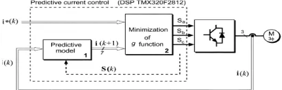
III.FCS-MPC OPERATING PRINCIPLE i) The Control Strategy
The concept behind model predictive control strategy is that only a finite number of possible switching states can be
generated by the inverter. In model predictive controller, a model of the system is used to predict the behaviour of the variable for each switching state. Based on the model of the system a cost or quality function is defined, which is used as a solution to optimization problem. These quality functions will evaluate for the predicted value of variables to be controlled. Prediction of future value of input variables is calculated for each possible switching state. The switching state that minimizes quality function is selected.Fig.1 shows the block diagram for model predictive controller.
Vol. 4, Issue 9, September 2015
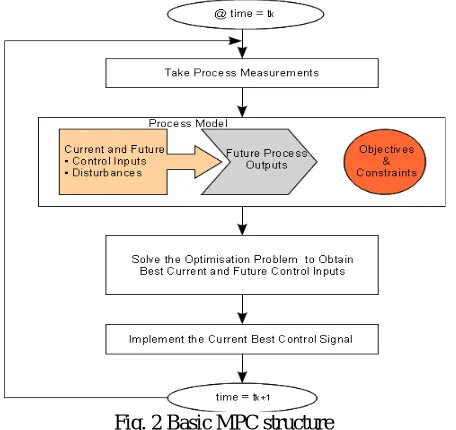
As a solution to power quality issues, appropriate switching pulse should be given to DSTSTCOM. DSTATCOM is a
shunt connected voltage source inverter .Determination of an appropriate control action S(t) i.e. the gate signal to
inverter that ,will drive a generic system variable x(t) usually the input current as close to desired reference value
x*(t).Since the control set is finite in number Si,with, i=1,...n. The future reference value x*(tk+1) can be estimated
via appropriate extrapolation methods. Figure 2 shows the basic MPC structure.
A discrete-time model of the load is needed to predict the behaviour of the variables using quality function i.e. the load current should be equal to the reference current.
As the inverter can be modelled as a system with a finite number of switching state, thus a finite control set MPC can be applied for DSTACOM [5].
Fig. 2Basic MPC structure
The power quality improvement is performed in the following steps.
1) The value of the reference current i*(k) is obtained, and load current i(k)is measured.
2) The model of the system is used to predict the value of the load current in the next sampling interval
i(k+1) for different voltage vector
3) The quality function g evaluates the error between reference and predicted currents in the next
sampling interval. The voltage that minimizes the current error is selected and applied to the load.
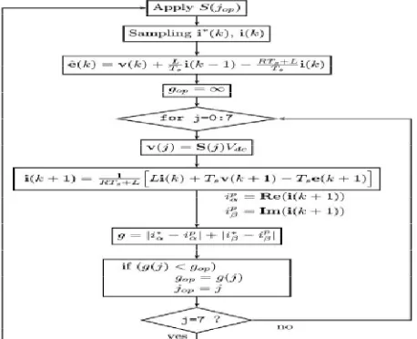
By selecting appropriate switching pulse to the inverter eliminate current harmonics and power factor correction can be done. Figure 3 shows the MPC generic algorithm.
ii) Quality Function
Quality function is defined to minimize the error between predicted value and the reference value of the quantity to be controlled. For eliminating current harmonics of distribution system load current is measured and its predicted value is calculated. Reference value of load current is calculated using d-q transformation.
The quality function is defined as [8],
g =| ∗− | + ∗−
(1)
Where and are the real and imaginary part of predicted load vector i(k+1), ∗ and ∗ are the real and
imaginary part of the reference current.
Vol. 4, Issue 9, September 2015
Fig. 3 FCS MPC generic algorithm
iii) DSTATCOM Model
The power circuit of the DSTATCOM considered in this work is shown in Fig.4
Fig. 4 DSTATCOM power circuit
The switching state of the inverter is determined by the gating signal Sa, Sb, and Sc as follows [8]:
Sa = 1, if S1 on and S4 off
0, if S1 off and S4 on
Sb = 1, if S1 on and S4 off
0, if S1 off and S4 on
Sc= 1, if S1 on and S4 off
0, if S1 off and S4 on
And can be expressed in vectorial form as,
S= ( + + ) (2)
Where a=
The output voltage space vector generated by the inverters are defined by,
V= ( + + ) (3)
Where , , is the phase to neutral voltages of the inverter. The load voltage vector v can be related to
switching state vector I by
V= (4)
Vol. 4, Issue 9, September 2015
Using MPC algorithm, appropriate voltage vector is selected so that the current THD can be reduced. Shape of current waveform can be maintained thus power factor correction can be obtained.
iv) Discrete Time Load Model
In a unbalanced three-phase load, the current can be defined a space vector by[8],
=2
3( + + ) (5)
Load current dynamics can be described by vector equation
= + + (6)
Where R , is the load resistance , L is the load inductance the voltage generated by the inverter ,e is the back emf.
A discrete-time model of the load current (6)for a sampling time Ts can be used to predict the future value of load
current with the voltage and measured current at the kth sampling instant.
Approximating the derivative
≈ ( )− ( −1) (7)
And replacing it in (6), the following expression is obtained or the future load current:
i(k)= [ ( −1) + ( )− ( )] (8)
Where the term RTs could be neglected if the sampling period is small enough and the load is mainly inductive.
One step forward in (8), the future load current can be determined by [8],
i(k+1)= [ ( ) + ( + 1)− ( + 1)] (9)
Equation (9) is the predicted value of load current, where i(k) is the current value of load current. The predicted value of load current is compared with the reference value of load current to generate the desired switching pulses for DSTACOM.
v) Switching Pulse Selection
In the proposed predictive algorithm, the voltage vector whose current prediction is closed to the expected current reference is applied to the load at next sampling. Predicted value of lad current and reference current are transformed to Alpha-Beta plane. The selected vector will be the one that minimizes the quality function[8]
= | ∗( + 1)− ( + 1)| + ∗ ( + 1)− ( + 1) (10)
Reference current value ∗( + 1) is measured through d-q transformation and its future value is predicted by second
order extrapolation. Figure 5 shows the implemented MPC_FC algorithm.
Vol. 4, Issue 9, September 2015
IV.SIMULATION RESULT
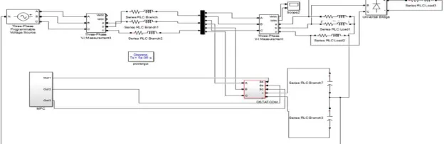
MATLAB software is used to evaluate the effectiveness of model predictive controller on DSTATCOM. Simulation parameters are given Table1.Fig. 6 shows the simulation model of MPC based DSTATCOM used for power quality improvement.
Fig. 6 Simulation Model For MPC Controller based Dstatcom
i) Before Compensation
Terminal voltage and load current before compensation are plotted and is shown in fig 7 and 8. Due to the presence of nonlinear load the terminal voltages and current unbalanced and distorted.THD value of load current is19.11% and load voltage is 12.53%.
TABLE I
SIMULATION PARAMETERS System Quantities Values
Source Voltage 415 V rms line to
line,50 Hz.
Feeder impedance Zs=1+j3.14Ω
Linear load Zla=30+j62.8Ω
Zlb=40+j78.8Ω
Zlc=50+j50.24Ω
Non linear load 50+j62.8 Ω
VSI parameters Vdc=650V,Cdc=2600μF,
Rf=1 Ω,Lf=22mH,Cfc=5
Μf
Fig. 7 Simulation output of load current of three phase four wire system with non linear load and without DSTATCOM
Fig. 8Simulation output of load voltage of three phase four wire system with non linear load and without DSTATCOM
0.4 0.41 0.42 0.43 0.44 0.45 0.46 0.47 0.48 0.49 0.5 -50 -40 -30 -20 -10 0 10 20 30 40 50 Time(s) C u rr e n t( A )
Vol. 4, Issue 9, September 2015
Fig. 9FFT analysis of PCC current of three phase three-wire system with non linear load and without DSTATCOM
(THD=19.11%)
Fig. 10 FFT analysis of PCC voltage of three phase three-wire system with non linear load and without DSTATCOM (THD=12.53%)
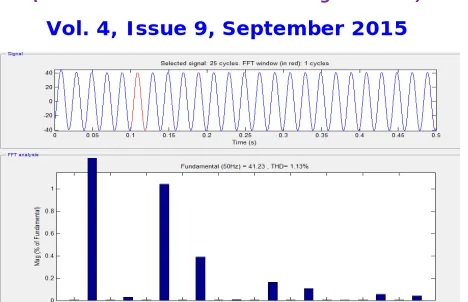
ii) Nominal operation
Using the Model Predictive controller method, terminal voltages and load currents in phases a, b, and c are shown in Fig .11 and 12; Thd value of load current is about 1.13% and that of load voltage is 2.43%.Thus by using MPC controller current and voltage harmonics can be reduced below 5% as per the IEEE 519 standard.
Fig. 11Simulation output of load voltage of three phase four wire system with non linear load and with Model
Predictive controller
Fig. 12 Simulation output of load current of three phase four wire system with non linear load and with Model Predictive controller
0 0.05 0.1 0.15 0.2 0. 25 0. 3 0. 35 0.4 0.45 0.5
-400 -300 -200 -100 0 100 200 300 400
Time(s)
V
o
lt
a
g
e
(V
)
0 0.05 0.1 0.15 0.2 0.25 0.3 0.35 0.4 0.45 0.5 -50
-40 -30 -20 -10 0 10 20 30 40 50
Time(s)
C
u
rr
e
n
t(
A
Vol. 4, Issue 9, September 2015
Fig. 13 FFT analysis of PCC current of three phase four-wire system with non linear load and with MPC controller based DSTATCOM (THD=1.13%)
iii) Power Factor Correction
Without DSTATCOM, the power factor of the system was about 0.8875. By connecting DSTATCOM to the distribution system, there is an improvement in power factor. Based on the controller used power factor improvement varies. Using MPC controller terminal voltage and current are in phase and unity power factor can be obtained.m has been improved. Figure 14,15, shows the voltage and current waveform before compensation and after compensation
Fig .14 Voltage and current waveform without DSTATCOM
Fig. 15 Voltage and current waveform with MPC control based Dstatcom
V. CONCLUSION
DSTACOM is a shunt compensating device used for power quality improvement. In this paper, model predictive controller based DSTATCOM for power quality improvement is done. In model predictive controller model of the system is used to predict the behaviour of the load current for each switching state. Model predictive controller will
generate switching pulses to operate VSI, which in turn reduce distortion in current and voltage waveform. These
controllers allow DSTATCOM to tackle power quality issues by providing power factor correction, harmonic elimination. MATLAB based simulink model is used to determine the effectiveness of the proposed controllers. From the simulation result it is concluded that MPC controller based DSTATCOM has better performance. Using MPC controller based DSTATCOM the current THD of the distribution system is reduced to 1.13% and unity power factor is achieved. Thus Power quality improvement is obtained.
REFERENCES
1. Dugan, R.C,M.F Mc Granaghan and H.W Beaty (1996).Electrical power syatem quality. New York, NY: McGraw-Hill-c1996
2. Sankaran .C , Power quality .Boca Raton London New York Washington, D.C.,2002
3. Hingorni, N.G and L. Gyugyi, Understanding FACTS. IEEE press,2000
4. Yong Hua Song , Allan T Johns, Flexible Ac Transmission, The Institution Of Electrical Engineers,London,U.K,1999
5. Samir Kouro,Ptricio Cortes, “Model Predictive Control-A Simple and Powerful Method to Control Power Converters,” IEEE Trans. Industrial
Electron., vol. 56, no. 6, pp. 1046–1053, May 2009.
0.4 0.41 0. 42 0. 43 0.44 0.45 0. 46 0.47 0.48 0. 49 0.5 -400 -300 -200 -100 0 100 200 300 400 Time(s) V olt a g e (V ) C u rr e n t( A )
0 0.05 0.1 0.15 0.2 0.25 0. 3 0.35 0.4
Vol. 4, Issue 9, September 2015
6. A. Ghosh and G. Ledwich, “Load compensating DSTATCOM in weak ac systems,” IEEE Trans. Power Del., vol. 18, no. 4, pp. 1302–
1309,Oct. 2003.
7. N. Patcharaprakiti, J. Thongpron, “Model Predictive Control Based on System Identification of Photovoltaic Grid Connected Inverter,”
International Journal of Information and Electronics Engineering, Vol. 2, No. 4, July 2012.
8. Jose Rodriguez, Jorge Pontt“Predictive Current Control Of Voltage Source Inverter” IEEE Trans. Industrial Elecronics., vol. 18, no. 4, pp. 1302–1309,Feb. 2007
9. A. Elnady and M. Salama, “Unified approach for mitigating voltage sag and voltage flicker using the DSTATCOM,” IEEE Trans. Power Del.,
vol. 20, no. 2, pt. 1, pp. 992–1000, Apr. 2005.
10. M. K. Mishra and K. Karthikeyan, “A fast-acting dc-link voltage controller for three-phase DSTATCOM to compensate ac and dc loads,”IEEE
Trans. Power Del., vol. 24, no. 4, pp. 2291–2299, Oct. 2009.
11. M. K.Mishra, A. Ghosh, and A. Joshi, “Operation of a DSTATCOM in voltage control mode,” IEEE Trans. Power Del., vol. 18, no. 1, pp. 258–
264, Jan. 2003.
12. M. K. Mishra, Chandan Kumar, “A Volage Controlled Dstatcom For Power Quality Improvement,” IEEE Trans. Power Del., vol. 22, no. 1, pp.
288–295, June. 2014.
BIOGRAPHY
Namitha.S was born in Kerala, India. She received the B.Tech. Degree in electrical engineering from Mahatma Gandhi University, Kerala, India , in 2013, and the M. Tech degree in She is currently pursuing her M.Tech in Power Systems at Saintgits College of Engineering, Kerala, India.