Article
1
Origami Needle Guide for CT-Guided Interventions
2
Austin Taylor 1, Sheng Xu 2, Bradford J. Wood 2 and Zion Tsz Ho Tse 1,*
3
1 School of Electrical and Computer Engineering; [email protected]
4
2 National Institutes of Health
5
* Correspondence: [email protected]; Tel.: 617-838-7006
6
7
Abstract: The objective of this study is to preliminarily evaluate a new CT-biopsy guidance device,
8
an origami needle guide. The device is created by laser cutting the structure from a sheet of
9
cardboard, 3D printing two radiocontrast agent grids on to the surface and folding the structure
10
into a rectangular prism with a viewing window. An abdominal imaging phantom was used to
11
evaluate the device through CT imaging and the targeting of lesions for needle insertion. The lesion
12
targeting trials resulted in a mean targeting error of 1.88 mm with a standard deviation of 0.73 mm.
13
The device attaches to the patient and is rigid enough to adequately support standard biopsy
14
needles, reducing the effect of gravity and the risk of laceration by the needles, making it potentially
15
advantageous for biopsy of superficial lesions and lesions approached from a horizontal orientation.
16
The device supports insertion of multiple needles at once, making it particularly suitable for
17
composite ablation using multiple needles. Another advantage of the device is that it can guide
off-18
axial needle insertion. The low-cost and disposability of the device make it well-suited for the
19
minimally invasive image guided therapy environment.
20
Keywords: origami; percutaneous biopsy; computed tomography; radiologic phantom; 3D printing
21
1. Introduction
22
Image-guided percutaneous biopsy has become an essential practice in modern medical care. Its
23
safety and efficacy have been verified in numerous studies [1-5]. Nevertheless, various complications
24
still arise, including hemorrhaging, hematomas, and injury to surrounding anatomical structures
[6-25
11]. The risk of complications may be amplified if the lesion location is difficult to reach or if patient
26
positioning is suboptimal.
27
Traditionally, CT-guided procedures are performed using the freehand technique. This can be
28
time consuming, especially if the target is small or difficult to reach. In these scenarios, numerous
29
needle insertions and CT scans may be required, thus increasing time, risk, needle manipulations,
30
tissue damage and radiation dosage. The development of guidance systems has improved the safety
31
and efficacy of image-guided interventional procedures. Various laser guidance systems have been
32
developed and implemented [12-14]. However, these systems require the needle to stay axially
33
aligned with the laser beam throughout the insertion and do not provide physical support to hold
34
the needle in place. Other guidance systems have aimed to address these issues but can only
35
accommodate a single needle [15-22].
36
The origami needle guide is an external localization device intended to address the limitations
37
of previous guidance systems. The device consisted of a cardboard structure created by folding an
38
origami pattern, two layers of a radiocontrast agent (RCA) grid, and a window for viewing the needle
39
insertion. Two-sided adhesive tape applied to the bottom of the device was used to mount the device
40
securely to the patient. When the desired angle of approach had been determined from the CT
41
images, the RCA gridlines provided valuable points of reference to act as a guide for precise
42
localization of lesions.
43
The device created several potential benefits for CT-guided percutaneous biopsy. First, since the
44
device is attached to the patient, it effectively loosely holds biopsy needles in place during imaging.
45
This is accomplished with a loose needle grip that reduces the risk of tissue laceration when the
46
physician needs to let go of the needles. This could be useful for superficial lesions, lesions in which
47
a horizontal approach is required, or for heavier or longer needles, where gravity requires needle
48
stabilization. Second, the device allows for multiple needles to be inserted, making it particularly
49
suitable for composite ablation using multiple needles. Finally, in highly inaccessible lesions that
50
require multiple plane angulations, the device may improve access to the target by allowing off-axial
51
needle insertion. This study aims to describe a novel, low-cost, and disposable device which might
52
provide a cost-effective method for holding and guiding a biopsy needle to a target location during
53
CT guided interventions.
54
2. Materials and Methods
55
2.1. Origami Needle Guide Design
56
The design of the origami needle guide originated from specifications suggested by
57
surgeons who operate the device as well as the MRI interventional radiologists. Suggestions
58
included:
59
• Disposable or able to be sterilized for future use.
60
• Attached securely to patient.
61
• Allow for in-plane or out of plane needle insertions.
62
• Support insertion of multiple needles.
63
• The device should not require additional software.
64
A template-based guidance system was determined to be the most effective way to satisfy the
65
suggested design specifications. The origami needle guide (Figure 1a) is constructed by laser cutting
66
an origami folding pattern (Figure 1b) into a cardboard material, 3D printing two RCA grids (Figure
67
1c) onto opposite sides of the folding pattern and folding the device into its final form. The folding
68
pattern is designed with computer-aided design (CAD) software, AutoCAD, and cut with a Full
69
Spectrum laser cutter. The folding pattern design consists of five panels which fold to form a 50 mm
70
x 100 mm x 100 mm rectangular prism with one side left open to serve as a viewing window. The
71
folded panels are held in place with eight tabs which fit snuggly into designated slots.
72
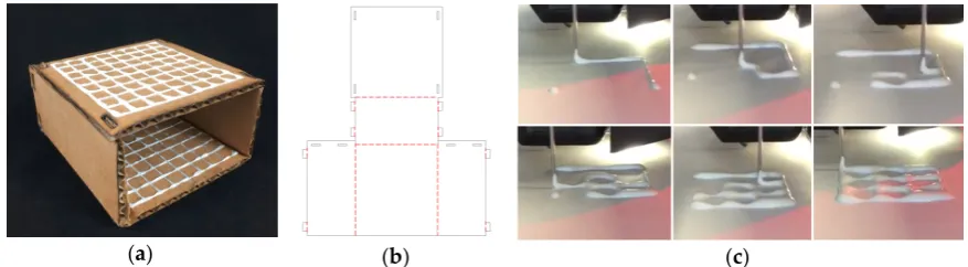
(a) (b) (c)
Figure 1. (a) Origami needle guide. (b) Needle guide folding pattern; solid black lines represent cut
73
lines and dashed red lines represent fold lines. (c) Printing RCA mixture.
74
2.2. Radiocontrast Agent Mixture
75
The RCA mixture was developed with three major design criteria in mind. The first and most
76
important goal was for the mixture to be bright enough to show up in a CT scan. Secondly, the
77
mixture needed to be applied to a surface as a liquid and be able to dry into a solid. Lastly, we
78
designed the RCA mixture to have a viscosity which would allow it flow through a 5 mm orifice for
79
extrusion via a syringe in a controlled manner. The resulting mixture was two parts Elmer’s glue, one
80
part barium sulfate, and one part water. Barium sulfate, Hi-LR from HiMedia Laboratiories was
81
chosen as the radiocontrast agent due to its exceptional radiopacity [23].
82
2.3. 3D Printing Radiocontrast Agent
84
To increase manufacturability and to decrease fabrication time, the RCA mixture grid was 3D
85
printed onto the surface of the device. A Fisher Scientific syringe pump was used to extrude the
86
mixture from an EXELINT 50 ml Luer Lock Tip syringe at a constant rate. A 5 mm diameter tube
87
connected the syringe to the side of an extruder head of a MakerBot 3D printer. The mouth of the
88
tube was aligned vertically with the 3D printer nozzle so that both contacted the printing surface at
89
the same time. A 3D printing job was run on the printer which moved the extruder head along the
90
path of the desired grid. The syringe pump was manually turned on and off when the print job started
91
and finished.
92
2.4. Lesion Targeting Equations
93
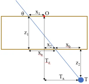
Figure 2 depicts a 2D schematic diagram of a needle trajectory through the device to a target
94
lesion. From the schematic, several equations can be derived to determine the proper coordinates (x1,
95
y1, x2, y2) in the top and bottom layers of the device through which to insert the needle to hit the target
96
lesion. Table 1 defines the variables used in the targeting equations. From a CT scan, the physician
97
can determine the desired insertion angle θ and the approximate width, length, and depth (Tx, Ty, Tz)
98
the target is from the origin of the device. Given the target depth Tz, the vertical distance from the
99
target layer to the bottom layer z2 can be found by
100
𝑧2= 𝑇𝑧− 𝑧1 (1)
Knowing the insertion angle, the horizontal distance from the second insertion location to the target
101
xb can be found by
102
𝑥𝑏 =
𝑧2
tan 𝜃 (2)
The target width Tx is the sum of the horizontal distance from the origin to the insertion location on
103
the bottom layer x2 and the horizontal distance from the bottom layer insertion location to the target
104
xb, so x2 can be found by
105
𝑥2 = 𝑇𝑥− 𝑥𝑏 (3)
The horizontal distance from the origin to the top layer insertion location can be found in a similar
106
manner by
107
𝑥𝑎=
𝑧1
tan 𝜃 (4)
𝑥1= 𝑥𝑎− 𝑥2 (5)
The insertion coordinates y1 and y2 can be found using the same equations, replacing x with y and
108
Tx with Ty. The insertion depth can be found by
109
𝑑 = 𝑥 + 𝑥 + 𝑧 + 𝑧 (6)
Table 1. Variables in needle insertion location equations (1) – (6).
110
Variable Description
T Target point; T = (Tx, Ty, Tz)
O Origin of device
θ Insertion angle
x1, x2 Horizontal distance from origin to insertion locations
z1, z2 Vertical distance from top layer to bottom layer, vertical distance from bottom
xa, xb Horizontal distance from top layer insertion location to bottom layer insertion location, horizontal distance from bottom layer insertion location to target
d Needle insertion depth
111
Figure 2. Schematic diagram of a needle insertion trajectory.
112
2.5. Workflow
113
The workflow of a typical procedure using the device is described below.
114
1. Perform a diagnostic CT or ultrasound scan of the target area to locate the target lesion to
115
determine positioning of the patient and the approximate skin entry point or region.
116
2. Place the needle guide on the patient and perform another CT scan to visualize the location of
117
the target lesion with respect to the needle guide.
118
3. Measure the approximate transverse, axial, and sagittal distances from the origin of the needle
119
guide to the target lesion on the CT console or workstation.
120
4. Use the needle insertion location equations (1) – (6) to determine the insertion locations and the
121
insertion depth. (This step may be semi-automated)
122
5. Insert the needle into the calculated locations of the needle guide, stopping insertion just after
123
traversing the skin.
124
6. Perform another CT scan in the same respiratory cycle to confirm the needle is aligned with the
125
target lesion. If yes, continue to step 7. If no, repeat steps 3 – 6.
126
7. Continue pushing the needle the entire calculated insertion depth to contact the target lesion.
127
8. Perform another CT scan to confirm the target lesion is on track to be sampled (depending upon
128
forward throw gun versus one snap gun). If yes, collect sample and remove the needle from the
129
patient. If no, retract the needle and repeat steps 6 & 7.
130
2.6. Validation of Targeting Accuracy
131
An abdominal phantom was used to perform lesion-targeting experiments (n = 30) to validate
132
the accuracy of the needle guide (Figure 3a). The phantom consisted of a 3D printed outer shell with
133
a soft plastic filling designed to match the density of human fatty tissue. The phantom contained
134
various soft 3D printed tumors located throughout the abdominal cavity which were used as targets
135
for needle insertions. The needle guide was positioned in the ventral insertion window of the
136
phantom and the origin of the needle guide was aligned with the CT laser to assure proper
137
craniocaudal angulation. After initial scans, the insertion locations and the insertion depth were
138
calculated, and the needle was inserted (Figure 3b). Using confirmation scans, transverse and sagittal
139
distance errors can be calculated based on the distance between the needle tip and the target tumor
140
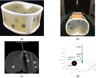
Figure 3. (a) 3D printed abdominal phantom for quantification of the lesion targeting error. (b)
142
Origami needle guide mounted to phantom. (c) CT image showing needle insertion. (d) Targeting
143
errors were measured in both transverse and sagittal directions of the needle relative to the target
144
lesion.
145
3. Results
146
3.1. Workspace Analysis
147
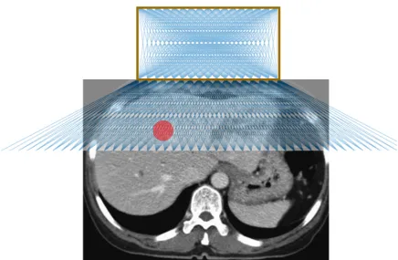
Figure 4 shows the possible needle trajectories in the transverse plane provided by the gridlines
148
on the origami needle guide. The discrete potential insertion locations correspond to RCA gridlines
149
as well as midlines between each of the RCA gridlines, illustrated by a raster engraving from the laser
150
cutter. The RCA grids provides a high density of discrete guidelines, while the puncturable device
151
material offers a continuous workspace for potential needle insertions.
152
(a) (b)
Figure 4. Illustration of possible needle trajectories in the transverse plane.
153
3.2. Phantom Study
154
The results of the needle insertion experiments performed on an abdominal phantom are
155
displayed in Figure 5. Preliminary results showed successful CT-guided biopsy needle placements in
156
an abdominal phantom. The mean targeting accuracy over all experiments was 1.88 mm with a
157
standard deviation of 0.73 mm. Figure 5a displays a box and whisker plot comparing the targeting
158
error between the sagittal and transverse axes, and Figure 5b depicts the radial error. The results
159
show that the error is relatively evenly distributed around the target.
160
(a) (b) (c)
Figure 5. Plots of the lesion targeting error in phantom studies. (a) Quartile plot of sagittal, transverse
161
and total targeting error. (b) Plot of radial error. Solid rings every millimeter, dashed rings ever 0.5
162
mm. (c) Bland-Altman plot of sagittal and transverse error measurements.
163
4. Discussion
164
The origami needle guide is a potentially useful tool for percutaneous biopsy or ablation.
165
Preliminary experiments showed successful lesion targeting in an abdominal phantom. One primary
166
advantage is that since the device is attached to the patient, it holds needles in place, allowing
167
scanning while the needle remains aligned along the desired trajectory, thus potentially reducing the
168
for superficial lesions and lesions that must be approached from a horizontal orientation. Another
170
major benefit is that the device allows for multiple needles to be inserted, making it applicable for
171
composite ablation using multiple needles. One more advantage of the device is that is can guide
off-172
axial needle insertion for highly inaccessible lesions that require multiple plane angulations.
173
Furthermore, the device can be manufactured quickly and inexpensively, making it disposable and
174
therefore ideal for the surgical environment.
175
Our preliminary evaluation exposed several limiting characteristics. The fixed nature of the
176
needle guide may be disadvantageous in situations where the target lesion moves with time, such as
177
with pulmonary lesions during respiration. Another limitation is that the large footprint of the device
178
can make it difficult to be used with ultrasound. In future work, we aim to manufacture the device
179
with biocompatible or sterilize-able materials. However, the biocompatibility and hemocompatibility
180
regulatory issues of having the needle traverse the material also need to be certified. Given the
181
limitations of our methodology, more rigorous testing in a specific clinical application would be
182
necessary to compare this device with established systems.
183
5. Conclusions
184
A novel device for assisting with CT-guided needle insertions is presented. The device was
185
fabricated by laser cutting the structure from a sheet of cardboard, 3D printing two radiocontrast
186
agent grids on to the surface and folding the structure into a rectangular prism with a viewing
187
window. The device was evaluated through CT imaging and targeting of lesions for needle insertions
188
in an abdominal imaging phantom. The results of the lesion targeting experiments showed a mean
189
targeting error of 1.88 mm with a standard deviation of 0.73 mm. The main advantages of the device
190
are that it attaches to the patient (potentially reducing the risk of laceration), it supports insertion of
191
multiple needles (making it particularly suitable for composite ablations), and it can guide off-axial
192
needle insertion. The low-cost and disposability are well-suited for interventional settings.
193
Author Contributions: Conceptualization, A.J.T. and Z.T.H.T.; methodology, A.J.T.; validation, A.J.T. and
194
Z.T.H.T.; formal analysis, A.J.T.; investigation, A.J.T.; resources, Z.T.H.T.; data curation, A.J.T.; writing—original
195
draft preparation, A.J.T.; writing—review and editing, S.X., B.W., and Z.T.H.T.; visualization, A.J.T.; supervision,
196
Z.T.H.T.; project administration, Z.T.H.T.; funding acquisition, A.J.T. and Z.T.H.T.
197
Funding: This research was funded by the National Institutes of Health (NIH) Bench-to-Bedside Award, the
198
NIH Center for Interventional Oncology Grant, the National Science Foundation (NSF) I-Corps Team Grant
199
(1617340), NSF REU site program 1359095, the UGA-AU Inter-Institutional Seed Funding, the American Society
200
for Quality Dr. Richard J. Schlesinger Grant, the PHS Grant UL1TR000454 from the Clinical and Translational
201
Science Award Program, the NIH National Center for Advancing Translational Sciences, and the Intramural
202
Research Program of the NIH.
203
Conflicts of Interest: The authors declare no conflict of interest. The funders had no role in the design of the
204
study; in the collection, analyses, or interpretation of data; in the writing of the manuscript, or in the decision to
205
publish the results. The conclusions are the opinions of the authors and do not reflect those of the US
206
Government which does not endorse products.
207
References
208
1. [1] H. Li, P. M. Boiselle, J. Shepard, B. Trotman-Dickenson, and T. McLoud, "Diagnostic accuracy and
209
safety of CT-guided percutaneous needle aspiration biopsy of the lung: comparison of small and large
210
pulmonary nodules," AJR. American journal of roentgenology, vol. 167, no. 1, pp. 105-109, 1996.
211
2. [2] L. Whitmire, J. Galambos, V. Phillips, C. Sewell, B. Erwin, W. Torres, R. Gedgaudas-McClees, and M.
212
Bernardino, "Imaging guided percutaneous hepatic biopsy: diagnostic accuracy and safety," Journal of
213
clinical gastroenterology, vol. 7, no. 6, pp. 511-515, 1985.
214
3. [3] S. G. Leffler and F. S. Chew, "CT-guided percutaneous biopsy of sclerotic bone lesions: diagnostic
215
yield and accuracy," AJR. American journal of roentgenology, vol. 172, no. 5, pp. 1389-1392, 1999.
216
4. [4] T. Welch, P. Sheedy 2nd, C. Johnson, C. Johnson, and D. Stephens, "CT-guided biopsy: prospective
217
5. [5] J. R. Haaga and R. J. Alfidi, "Precise biopsy localization by computed tomography," Radiology, vol.
219
118, no. 3, pp. 603-607, 1976.
220
6. [6] E. vanSonnenberg, G. Casola, M. Ho, C. Neff, R. Varney, G. Wittich, R. Christensen, and P. Friedman,
221
"Difficult thoracic lesions: CT-guided biopsy experience in 150 cases," Radiology, vol. 167, no. 2, pp.
457-222
461, 1988.
223
7. [7] M. K. Mody, E. A. Kazerooni, and M. Korobkin, "Percutaneous CT-guided biopsy of adrenal masses:
224
immediate and delayed complications," Journal of computer assisted tomography, vol. 19, no. 3, pp.
434-225
439, 1995.
226
8. [8] C. C. Wu, M. M. Maher, and J.-A. O. Shepard, "Complications of CT-guided percutaneous needle
227
biopsy of the chest: prevention and management," American Journal of Roentgenology, vol. 196, no. 6, pp.
228
W678-W682, 2011.
229
9. [9] P. Loubeyre, M. Copercini, and P.-Y. Dietrich, "Percutaneous CT-guided multisampling core needle
230
biopsy of thoracic lesions," American Journal of Roentgenology, vol. 185, no. 5, pp. 1294-1298, 2005.
231
10. [10] M. Bernardino, M. Walther, V. Phillips, S. Graham Jr, C. Sewell, K. Gedgaudas-McClees, B.
232
Baumgartner, W. Torres, and B. Erwin, "CT-guided adrenal biopsy: accuracy, safety, and indications,"
233
American journal of roentgenology, vol. 144, no. 1, pp. 67-69, 1985.
234
11. [11] A. Olscamp, J. Rollins, S. S. Tao, and N. A. Ebraheim, "Complications of CT-guided biopsy of the spine
235
and sacrum," Orthopedics, vol. 20, no. 12, pp. 1149-1152, 1997.
236
12. [12] K. Brabrand, T. Aaløkken, G. Krombach, R. Günther, R. Tariq, A. Magnusson, and P. G. Lindgren,
237
"Multicenter evaluation of a new laser guidance system for computed tomography intervention," Acta
238
Radiologica, vol. 45, no. 3, pp. 308-312, 2004.
239
13. [13] P. R. Frederick, T. H. Brown, M. H. Miller, A. L. Bahr, and K. Taylor, "A light-guidance system to be
240
used for CT-guided biopsy," Radiology, vol. 154, no. 2, pp. 535-536, 1985.
241
14. [14] A. Gangi, B. Kastler, J.-M. Arhan, A. Klinkert, J.-M. Grampp, and J.-L. Dietemann, "A compact laser
242
beam guidance system for interventional CT," Journal of computer assisted tomography, vol. 18, no. 2, pp.
243
326-328, 1994.
244
15. [15] A. Magnusson and D. Åkerfeldt, "CT-guided core biopsy using a new guidance device," Acta
245
Radiologica, vol. 32, no. 1, pp. 83-85, 1991.
246
16. [16] A. M. Palestrant, "Comprehensive approach to CT-guided procedures with a hand-held guidance
247
device," Radiology, vol. 174, no. 1, pp. 270-272, 1990.
248
17. [17] C. Ozdoba, K. Voigt, and F. Nüsslin, "New device for CT-targeted percutaneous punctures,"
249
Radiology, vol. 180, no. 2, pp. 576-578, 1991.
250
18. [18] A. Magnusson, E. Radecka, M. Lönnemark, and H. Raland, "Computed-tomography-guided
251
punctures using a new guidance device," Acta Radiologica, vol. 46, no. 5, pp. 505-509, 2005.
252
19. [19] C. Roberts, W. Morrison, D. Deely, A. Zoga, G. Koulouris, and C. Winalski, "Use of a novel
253
percutaneous biopsy localization device: initial musculoskeletal experience," Skeletal radiology, vol. 36, no.
254
1, pp. 53-57, 2007.
255
20. [20] G. Onik, P. Costello, E. Cosman, T. Wells Jr, H. Goldberg, A. Moss, R. Kane, M. Clouse, W. Hoddick,
256
and S. Moore, "CT body stereotaxis: an aid for CT-guided biopsies," American journal of roentgenology,
257
vol. 146, no. 1, pp. 163-168, 1986.
258
21. [21] G. D. Reyes, "A guidance device for CT-guided procedures," Radiology, vol. 176, no. 3, pp. 863-864,
259
1990.
260
22. [22] G. Reuther, "A device for CT-guided needle punctures," Cardiovascular and interventional radiology,
261
vol. 14, no. 3, pp. 191-194, 1991.
262
23. [23] A. J. Megibow and M. A. Bosniak, "Dilute barium as a contrast agent for abdominal CT," American
263
Journal of Roentgenology, vol. 134, no. 6, pp. 1273-1274, 1980.