Real Time Biometrics Based Vehicle
Security Alert System with GPS and GSM
Technology Using IOT
N.Nagaraju1, P.Kaviyapriyadharshini2, R.Madhumitha3, J.Mahalakshmi4, K.Nivetha5
Assistant Professor, Department of ECE, Adhiyamaan College of Engineering, Hosur, Tamilnadu, India1
U.G Student, Department of ECE, Adhiyamaan College of Engineering, Hosur, Tamilnadu, India2,3,4,5
ABSTRACT: In this current world where technology is growing up day by day and the need for security is also increasing in all areas. Simultaneously, protective the vehicle against larceny is additionally vital.When the vehicle is purloined, not a lot of response or various may well be accessible to assist the owner of the vehicle to search out it back. The main intent of this design is to protect the vehicle from any unauthorized access, easy-to-use, reliable and economical fingerprint recognition technique. This vehicle security system intimates the standing of the vehicle to the authoritative person (owner) exploitation international System for Mobile (GSM) communication technology.If the user is certified, vehicle authentication is allowed. The SMS will be sent to the owner and the engine will be immobilized. By using GPS technology, the location of the vehicle can be identified very easily. The image model for the safety system is made on the embedded platform.
KEYWORDS: Biometric certification, Microcontroller Unit (MCU), Global System for Mobile (GSM), Global Positioning System (GPS), Engine Controller Unit, Anti-theft contrivances.
I. INTRODUCTION
Nowadays security is the high concern at present vehicle usage. Simultaneously protecting the vehicle from the theft and also another type of burglary activities. Previously security system contains some sensor, alarm system and cost of the sensor is also high. If the vehicle is stolen no alternative methods are available to help the owner of the vehicle to find vehicle back. The main aim of our paper is to provide high security to the vehicle and allow only authenticated users. It is also user-friendly, fast access, fingerprint recognition technology along with GPS and GSM system
II. PROPOSED SYSTEM
The proposed system includes biometric fingerprint technology which enhances the security of the vehicle and allows only authenticated users. To provide high security, the system includes GPS and GSM for tracking and SMS alert to avoid the theft vehicle from unauthorized users and to give alert to the owner of the vehicle. One of the main advantage of this is low cost when compared to other security system which is available in the market. This can be implemented in any type of the vehicle to provide high security to vehicle.
III.BLOCK DIAGRAM
IV.HARDWARE REQUIREMENTS
Power supply unit
The ac voltage, generally a hundred and twenty V rms, is connected to an electrical device, that steps that ac voltage right down to the extent for the specified dc output.
PIC Microcontroller (16F877A)
PIC may be a general purpose method that incorporates the range of features of a microchip structure on to the single bit.They are smaller in size, consumes less power and cheap. Various PICs provide totally different sorts of reminiscences. EEPROM, EPROM, FLASH are some of the recollections of which FLASH is the most latelyindustrializedMachinery that's in employment in PIC16F877A is flash machinery, in order that information is maintained even once the ability is changed. Easy Programming and tracing other features of PIC 16F877A.
POWER SUPPLY
MICRO CONTROLLER VIBRATION
SENSOR FINGER PRINT SENSOR
GSM MODEM
GPS MODULE
WIFI MODULE
LCD DISPLAY
RELAY DRIVER 1
RELAY DRIVER2
DC MOTOR
Finger print module
Enrolling fingerprint, a user needs to enter the finger 2-4 times for every one finger, process finger images with many times, store generate templates on a module. When fingerprint matching, enrol and process verified fingerprintimage And then matching with module (if match with appointing templates on the module, named fingerprint verification, For 1:1 matching method; if match with many templates on the module, named fingerprint search method also named1:N)system will return the matching result, successor failure.
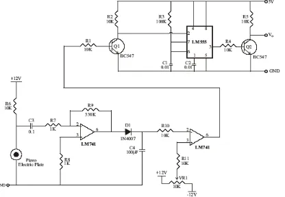
Vibration sensor
Fig 4.1Circuit diagram of vibration sensor
The square pulse is given to base of BC 547 transistors each time the positive side of the square pulse is comes the transistor comportments emitter and collector side is short-circuited as a result of the semiconductor device is act as the switch. The collector side is linked to trigger terminal of the 555 IC. When the semiconductor device is conducted negative signal is given to the trigger terminal as a result of the electrode is connected to the ground aspect.The sq. pulse is given to base of the Q2 junction transistor.The junction transistor is activated and switch OFF depends upon the sq. pulse.The Q2 electronic transistor output is zero to 5V pulse. Whenever the Piezo electric platter sense the pulsation the Q2 transistor outputs the 0 to 5V pulse. This pulse is given to microcontroller or different connected circuit to tell that vibration has occurred.
LCD Display
LCD show liquid crystal displays are also used as numerical indicators, particularly in digital watches wherever their a lot of smaller current wants than LED displays (microamperes related with mill amperes) extend battery life. Liquid crystals area unit carbon-based (carbon) compounds thatshow each solid and liquid things.
Features:
16 Character x 2 lines 5 x 7 dots with cursor Built in controller
+5v power supply(also available for +3v) 1/16 duty circle
Keypad
Wi-Fi module
Node MCU is abuilt-upcradleIoT platform. Thesupercomputerprogram that goes on the ESP8266 Wi-Fi SoC and hardware that is established on the ESP-12 section. The term NodeMCU by default means to the program as an alternative of the DevKit.The firmware uses the eLua scripting etymological. It is maintained by the eLua plan and plotted on the Espressif Non-OS SDK for ESP8266. It procedurescertain open materials comes, like Lua-cjson, and spiffs.
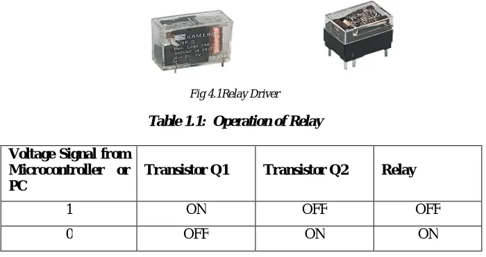
Relay Driver 1(DC motor) & Relay Driver 2(DC motor for side stand)
A relay is an electrically operated switch. Current rolling through the loop of the relay creates a energy field that draws a switch and changes the control contacts.The loop current is taking place or tainted therefore relays have 2 switch sites and that they square degree double throw (changeover) switches.Relays enable one circuit to change a second circuit which might utterly break free the primary.For example, a coffee voltage battery circuit will use a relay to change a 230V AC mains circuit.There is no electrical association within the relay between the 2 circuits.
Fig 4.1Relay Driver
Table 1.1: Operation of Relay
Voltage Signal from Microcontroller or PC
Transistor Q1 Transistor Q2 Relay
1 ON OFF OFF
0 OFF ON ON
GPS module
In order for GPS to figure, a grid of satellites was placed into path around planet Earth, every propagation a selected signal, with some radio radiation. This signal may be received by a coffee value, low technology aerial, despite the fact that the signal is extremelyweak.The data is definite that the GPS software can identify the satellite broadcasting, its position in space, and estimates the time that the pointer took to travelfrom the satellite to the GPS receiver.
GSM modem
GSM tracking has the advantage of low set-up costs and fast roll-out.It works with any current portable via its GSM SIM card.So long as the user gives you permission, you can track existing mobile phones simply by registering them with your chosen LBS provider. The GSM modem used to transmit the GPS-derived data back to the base has the added benefit of allowing SMS or other forms of a data message to be passed between the driver and transport office via a suitable in -cab interface.
IV.RESULTS
otherwise not. Thus by implementing this design is comparatively simple, cheap and stress-free for the user to protect their vehicle against theft with greater security and by a conventional lock and key. Implementing this design is comparatively simple, cheap and stress-free for the user to protect their vehicle against theft with greater security and
Fig 5.1 Hardware Output
V. CONCLUSION AND FUTURE SCOPE
The developed system ensures that solely licensed drivers will drive the vehicle and misuse of vehicles by others will be prevented.The system makes sure that vehicles access is given to only authorize personal and thus accidents can also be prevented.The developed system is the future enhancement for gearing system to protect vehicle from unauthorized user with real-time embedded biometric based ignition system in vehicle. Thisis a novel methodology of conniving and collection an inexpensive, packed in felony system for Associate in Nursing automobile that is very reliable.The present module can be extended to including a GSM-GPS module for additional safety so that even if the vehicle is stolen by trespassing the security module can relocate the vehicle using satellite coordination.
REFERENCES
[1] Visa M. Ibrahim “Microcontroller Based Anti-theft Security System Using GSM Networks with Text Message as Feedback”
Published in International Journal of Engineering Research and Development e-ISSN: 2278-067X, p-ISSN: 2278-800X, www.ijerd.com Volume 2, PP. 18-22, Issue 10 (August 2012).
[2] UpendranRajendran and Albert Joe Francis, Anti Theft Control System Design Using Embedded System, Proc. IEEE, vol. 85, page no.
239- 242, 2011.
[3] Omidiora E. O.(2011) “A Prototype of a Fingerprint Based Ignition Systems in Vehicles” Published in European Journal of Scientific
Research ISSN 1450216X Vol.62 No.2 (2011), pp. 164-171 © Euro Journals Publishing, Inc. 2011.
[4] Jayanta Kumar Pany and R.N. Das Choudhury, Embedded Automobile Engine Locking System Using GSM Technology, Int. Journal
of Instrumentation, Control and Automation (IJICA) ISSN : 2231-1890 Volume -1, Issue -2, 2011.
[5] T.Ignatenko and F. M. J Williams, Biometric Systems: Privacy and Secrecy aspects, IEEE Transactions on Information Forensics and
security, IEEE, vol.4, no.4, December 2009.
[6] Anil Jain, Arun Ross and SalilPrabhakar, “Fingerprint Matching Using Minutiae And Texture Features,” Fingerprint Matching Using