Topology Optimization and Structural
Analysis of Continuous Linear Elastic
Structures using Optimality Criterion
Approach in ANSYS
Kishan Anand1, Anadi Misra2
P.G. Student, Department of Mechanical Engineering, G.B.P.U.A.T., Pantnagar, U.S.Nagar, India1
Professor, Department of Mechanical Engineering, G.B.P.U.A.T., Pantnagar, U.S.Nagar, Uttarakhand, India2
ABSTRACT: The technique used for topological optimization and structural analysis in the present research paper is numerical methods. The finite element analysis of the problems is done by the software package known as ANSYS which is purely based on numerical technique.
The present paper consists of optimal topology, compliance value, deformed shape, displacement and von-Mises stress of the structures such as column, beam, short beam and flat plate with a central circular hole using optimality criterion approach through ANSYS.
KEYWORDS: Topology Optimization, Column, Pressurized Beam, ANSYS, Flat Plate, Central Circular Hole, Compliance, O C Approach, etc…
I. INTRODUCTION
This paper presents the optimal topology of the linear elastic structures such as a column, beam, short beams and a flat plate with a circular hole at its centre. For the above mentioned structures the plane state of stress is considered. The topology optimization and structural analysis is performed using ANSYS software package. The software is based on mathematical calculations. The numerical technique used in the software is optimality criterion approach. The above mentioned problems are considered to be linearly elastic isotropic structures. In this research paper the parameters obtained for the above mentioned structures are optimal topology, compliance, deformed shape with undeformed edge, displacement and von-Mises stress.
Bendsoe and Kikuchi 1988, Optimal shape design of structural elements based on boundary variations results in final designs that are topologically equivalent to the initial choice of design, and general, stable computational schemes for this approach often require some kind of remeshing of the finite element approximation of the analysis problem. The computation of effective material properties for the anisotropic material is carried out using the method of homogenization. Computational results are presented and compared with results obtained by boundary variations [1]. Suzuki and Kikuchi 1991, Shape and topology optimization of a linearly elastic structure is discussed using a modification of the homogenization method introduced by Bendsoe and Kikuchi together with various examples which
may justify validity and strength of the present approach for plane structures [2].
analysis algorithms used in this software packages. Therefore the major challenge faced by researchers in structural optimization is to develop methods that are suitable for use with such software packages. Another major challenge is the high computational cost associated with the analysis of many complex real-life problems [3].
Many approaches follow a sequential approximate optimization (SAO) approach to build and solve a series of approximate optimization sub-problems [3].
Philip A. Browne 2013, in structural design, topology optimization can be regarded as an extension of methods for size optimization and shape optimization. Size optimization considers a structure which can be decomposed into a finite number of members. Each member is then parameterized so that, for example, the thickness of the member is the only variable defining the member. Size optimization then seeks to find the optimal values of the parameters defining the members [4].
X. Huang, Y. M. Xie 2009, according to them; as a result, one will obtain a structure with the highest stiffness for a given volume while the displacement of a certain node does not exceed a prescribed limit [5].
Hui Zhang & Xiong Zhang & Shutian LiuIn 2008, presented that the load surfaces are formed by the connection of the real boundary of elements and the pressures are transferred directly to corresponding element nodes [6].
Gunwant et al. 2013, presented that the topological optimization capabilities of a commercially available finite-element solver ANSYS have been employed through APDL (ANSYS Parametric Design Language) to find the optimal layout of material in the continuous elastic isotropic structures. Common continuum structures configurations have been selected for topology optimization. The structures are modeled in ANSYS assuming that there is a plane state of stress in each model [7].
Chaudhuri (1993) proposed a completely sequential scheme for optimal design in parametric nonlinear problems [8]. The topology optimization attains the goal to find the optimal topology of the material used such as global stiffness and it is performed when the parameter volume reduction is taken to be constraint.
In this work, maximization of static stiffness has been considered. This can also be stated as the problem of minimization of compliance of the structure.
The optimality criterion (OC) method require a penalization scheme such as SIMP (Solid Isotropic Material with Penalization) for evolving true, material and void region in the design domain.
II. MATERIALS AND METHODS
For the present investigation the material has been taken as the 2-dimensional structures and the method used is optimality criterion method to get the final topology and structural nodal analysis of the structures keeping the structures stable or not undergoing fracture and plane state of stress is considered for all the mentioned problems (structures). For this a software package ANSYS is used which performs optimization and analysis using optimality criterion approach and some FEM equations.
2.1 Topology Optimization
Topology optimization method is a technique to find out optimal material distribution within predefined design domain. It can give the best conceptual design that can satisfy all design requirements. Topology optimization problem includes objective function, design domain and design constraints. Objective function represents the goal of the optimization method which is to be minimized or maximized [9].
2.2 Solid Isotropic Material with Penalization (SIMP) Method:
density raised to some power times the material properties of solid material. Dadalau et al. [2008] presented a new penalization scheme for the SIMP method [10].
2.3 The Optimality Criterion approach
The discrete topology optimization problem is characterized by a large number of design variables, N in this case. It is therefore common to use iterative optimization techniques to solve this problem, e.g. the method of moving asymptotes, OC method, to name two. Here we choose the latter. At each iteration of the OC method, the design variables are updated using a heuristic scheme. OC method was analytically formulated by Prager and co-workers in 1960. It was later developed numerically and become a widely accepted structural optimization method (Venkaya et al. 1968). OC methods can be divided into two types. One type is rigorous mathematical statements such as the Kuhn-Tucker conditions. The other is algorithms used to resize the structure for satisfying the optimality criterion. Different optimization problems require different forms of optimality criterion.
This paper considers the maximization of static stiffness through the inbuilt topological optimisation capabilities of the commercially available FEA software to search for the optimum material distribution in two plane stress structures. The optimum material distribution depends upon the configuration of the initial design space and the boundary conditions (loads and constraints).
The goal of the paper is to minimize the compliance of the structure while satisfying the constraint on the volume of the material reduction.
Minimizing the compliance means a proportional increase in the stiffness of the material. A volume constraint is applied to the optimisation problem, which acts as an opposing constraint [11].
2.3.1 Element Type
Selection of element type is one of the most important features in topology optimization through ANSYS. Topological optimization in ANSYS supports 2-D and 3-D solid elements. Sigmund and Clausen [2007] suggested a new way to solve pressure load problems in topology optimization. Using a mixed displacement–pressure formulation for the underlying a finite element problem. By this technique the model can be discretized into following element type: (a). 2-D Solids: Plane 82
(b). 3-D Solids: Plane 95
Plane 82: This is an 8-node element and is defined by eight nodes having two degree of freedom at each node. The translations of elements in the nodal x and y- directions shown in Fig-1(a). The element may be used as a plane element or as an axi-symmetric element. The element has plasticity, creep, swelling, stress stiffening, large deflection, and large strain capabilities [12].
(a) Quad and tri elements (b) 3 D rectangular element Fig- 1: (a) Plane82 element with quad and tri options and (b) Rectangular domain meshing
Solid95: This element type has quadratic displacement behaviour and is well suited to model irregular meshes (such as produced from various CAD/CAM systems). The elements are defined by 20 nodes having three degrees of freedom at each node: translations in the nodal x, y, and z directions as shown in figure-1(b).The elements also have plasticity, creep, swelling, stress stiffening, large deflection and large strain capabilities.
III. PROBLEM FORMULATION
In this section, the paper presents to carry out topology optimization of the 2-dimensional structures. The structures
with the Young’s modulus (E) as 210 GPa and the Poisson’s ratio (ʋ) of 0.3. All the four structures are considered to be
linearly elastic isotropic material. The structures are solved for different individual loading and boundary conditions. The constraint parameter volume fraction is 50% for all the given four structures.
3.1 Column (Model 1): The design domain of square column of unit dimensions and the 1000 N load is applied on three points of the top of the design domain and the base is fixed, as shown in Figure-2(a).The properties for given problem are E=2.1E5 MPa and Poisson’s ratio is 0.3 for volume fraction of 0.5.
3.2 Model 2: Example 2 is a stiffness topology optimization problem for a beam structure of dimensions 100mm x 50mm which is simply supported by both ends and 10 MPa pressure load is vertically applied on the upper edge as depicted in Fig-2(b). The computations are performed in the domain with 1.25 square element edge length (four-node plane stress elements).
3.3 Model 3: In this example, a three point supported short beam of dimensions are in the length-breadth ratio of 2:1 subjected to the three point loads on the top edge is optimized and analyzed. The admissible design domain, boundary conditions, and initial load conditions are shown in Fig-2(c). The point loads are of magnitude 1000 N. The design domain is discretized by 0.025 square element edge length.
(d) Problem with Boundary Conditions and Loading Conditions for Flat Plate with Central Circular Hole Fig-2:Design domain of(a) column (model 1) problem, (b) beam (model 2), (c) three point supported short beam (model 3) and(d) Geometry and
boundary conditions of elastic plate with central elliptical hole (model 4)
3.4 Model 4: In structure 4, the topology optimization and nodal analysis of a rectangular plate with a central circular hole of dimensions 400mm x 100mm with central hole of diameter 10mm under transversely downwards static load at right end of top edge of magnitude 1000 N has been analyzed using optimality criterion approach in ANSYS. In the
fig-2(d) centre of plate depicts a fixed circular hole, taking hole as constraint in all DoF (considering it as fixed for some purpose).
IV. RESULTS
In this section the optimal topology and structural analysis of the structures are obtained using Optimality Criterion Approach in ANSYS. Further the graphs are plotted between iteration and values of compliances for all the structures. The results of nodal solution for the structures are shown in the table-1 given below.
4.1 Optimized Shape:
Figure-3(a), shows the topologically optimized shape through ANSYS for a Simple Column (Model 1). Figure-3(b), shows the topology optimization through ANSYS obtained for the beam (structure 2) under the given boundary conditions which is obtained by using optimality criterion approach.Figure-3(c), represents the topologically optimized shape as obtained for the three point supported short beam (model 3) and three point loads are applied on top edge is obtained by using optimality criterion using ANSYS.
Fig-3: Optimal design for (a) Model 1, (b) Model 2, (c) Model 3 and (d) Model 4 using optimality criteria approach
Figure-3(d) shows the topologically optimized shape through ANSYS for an elastic plate with circular hole in its centre (model 4) under given boundary conditions.
(d) Optimal Topology of Flat Plate in ANSYS
4.2 Compliance:
For structure 1, the initial value of compliance was 254.908 Nmm and the final value as obtained after 28 iterations is 107.223 for 6400 number of elements. A reduction of 147.685 from its initial value. Variation of compliance with iteration is shown in the graph-4(a) below. Vertical axis represents the compliance and the horizontal axis represents the iteration. For structure 2, the initial value of compliance was 62.1095 Nmm and the final value as obtained after 26 iterations is 17.1153 Nmm. A reduction of 44.9942 from its initial value. Variation of compliance with iteration is shown in the graph-4(b) below. Vertical axis represents the compliance and the horizontal axis represents the iteration.
Fig-4: Compliance versus Iteration plot for (a) Model 1, (b) Model 2, (c) Model 3 and (d) Model 4 using optimality criteria approach
For structure 3, the initial value of compliance was 379.61 Nmm and the final value as obtained after 16 iterations is 104.25. A reduction of 275.36 from its initial value. Variation of compliance with iteration is shown in the graph-4(c) below. Vertical axis represents the compliance and the horizontal axis represents the iteration.
For structure 4, the initial value of compliance was 1220.9 Nmm and the final value as obtained after 39 iterations is 489.87. A reduction of 731.03 from its initial value. Variation of compliance with iteration is shown in the graph-4(d) below. Vertical axis represents the compliance and the horizontal axis represents the iteration.
4.3 Structural Analysis
4.3.1 Nodal Solution using ANSYS
The structural analysis has been also done for the above mentioned structures. The table-1 given below shows the displacements and stresses for all the four structures. From the figure-5: (a), (b), (c) and (d) we can see the deformed shapes with undeformed edge for the above mentioned problems and given boundary conditions.
0 100 200 300
0 10 20 30
C o m p lia n ce Iteration 0 20 40 60 80
0 10 20 30
C o m p lia n ce Iteration 0 100 200 300 400
0 2 4 6 8 10 12 14 16 18
C o m p lia n ce Iteration 0 500 1000 1500
0 5 10 15 20 25 30 35 40 45
C o m p lia n ce Iteration
(a) Graph Plot for Column (Model 1) (b) Graph Plot for Beam (Model 2)
Fig-5(a) represents deformed Shape for structure (1) and bottom & top edge of the column shows boundary condition and applied load on three points respectively. Fig-5(b) represents deformed Shape for the beam simply supported at bottom ends and pressure load applied on top surface of the beam. Fig-5(c) shows deformed Shape for 3 point supported short beam at bottom and three point load applied on top edge.
Fig-5: Deformed shape with undeformed edge representation for (a) Model 1 (Column), (b) Model 2 (Beam), (c) Model 3 (3 Point Supported Short Beam) and (d) Model 4 (Flat Plate with Central Circular Hole) using optimality criteria approach in ANSYS
The representation of deformed shape with undeformed edge of the flat plate having a circular hole in its centre is shown in the Fig-5(d).
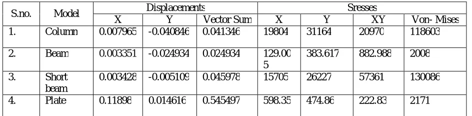
Numerical values obtained for displacements, stresses and von Mises stress for above mentioned four structures by using Optimality Criterion Approach in ANSYS is shown in table given below.
Table -1: Structural Analysis with Nodal Solutions (Displacements &Stresses)
S.no. Model Displacements Sresses
X Y Vector Sum X Y XY Von- Mises
1. Column 0.007965 -0.040846 0.041346 19804 31164 20970 118603
2. Beam 0.003351 -0.024934 0.024934 129.00
5
383.617 882.988 2008
3. Short
beam
0.003428 -0.005109 0.045978 15705 26227 57361 130086
4. Plate 0.11898 0.014616 0.545497 598.35 474.86 222.83 2171
From the table-1, the structural analysis of all the above mentioned four structures is given which are obtained using optimality criterion approach in ANSYS. The von Mises stress is needed to the designer for better design.
V. CONCLUSIONS
The optimized shapes, deformed shapes with undeformed edge, compliance value, displacements and stresses of all the models mentioned above are obtained using optimality criteria in ANSYS which is the method of topological optimization and nodal solution. Also the compliance obtained from optimality criterion approach using ANSYS and minimized during iterations till convergence occurs. Thus ANSYS is an effective tool for topological optimization&
(d) Deformed Shape with Undeformed Edge for Central Circular Hole Plate
nodal solution and the results obtained by ANSYS are effective and quick. For further work structural analysis has been done such as maximum displacements and von Mises stresses are obtained for the above mentioned structures. The following conclusions can be drawn from the above analysis of the mentioned all four structures:
(1). ANSYS provides a very suitable way of determining optimal topology, compliance, deformations, displacements and stresses induced in any body.
(2). ANSYS obtained results are comparable to the analytical results in case of nodal solution of the structures and they can be used for the simulation of complex geometries.
(3). As compared to the analytical method which only gives the numerical value of stress, ANSYS gives a more intuitive feel to the designer by displaying stress contours throughout the design of the structures.
(4). As the compliance value of structure is minimized the structure gets more stiffened.
(5). As expected, the maximum deflection occurs when the analysis is done for the optimal topology of the structures.
ACKNOWLEDGEMENT
The present paper is written under the guidance of Dr. Anadi misra. I am very thankful to him and Dheeraj Gunwant, Ph. D. scholar from GBPUA&T for supervising me through this work and for kindly supporting me in ANSYS software and helping enormously with their technical knowledge.
REFERENCES
[1]. Martin Philip Bendsoe and Noboru Kikuchi. “Generating optimal topologies in structural design using a homogenization method”. Computer Methods in Applied Mechanics and Engineering, 71(2):197{224, November 1988.
[2]. Suzuki, K. and Kikuchi, N. 1991. “A homogenization method for shape and topology optimization”. Comput. Mech. Appl. Mech. Eng. 93:291-318.
[3]. Raphael T. Haftka and ZaferGurdal. “Elements of Structural Optimization”. Kluwer Academic Publishers, third edition, 1991. [4]. Philip Anthony Browne 2013, “Topology optimization of linear elastic structures”, Thesis, University of bath.
[5]. X. Huang · Y. M. Xie [2010], (Received: 22 August 2008 / Revised: 26 December 2008 / Accepted: 19 March 2009 / Published online: 9 April 2009 © Springer-Verlag 2009).
[6]. H. Zhang et al.Worked on short pressurized beams for topology using NAND- SIMP method.
[7]. DheerajGunwant 2012, “Topology optimization of continuum structures using optimality criterion approach in ANSYS”, Thesis, G.B. Pant university of agriculture and technology.
[8]. R. A. Chaudhuri, “Stress concentration around a part through hole weakening laminated plate”, Computers & Structures, vol. 27(5), pp. 601-609, 1987.
[9]. Sigmund, O. and Clausen, P. M. 2007. “Topology optimization using a mixed formulation: An alternative way to solve pressure load problem”. Comput. Meth. Appl. Mech. Eng. 196:1874-1889
[10]. Dadalau.A, Hafla, Verl 2009. “A new adaptive penalization scheme for topology optimization”, German Acadmey society for Production Engineering, 3;427-434.
[11]. Prager 1960, first described Optimality Criterion Approach.
[12]. Mohammad Rouhli 2009, “Topology optimization of continuum structures using element exchange method”, Thesis, Mississippi state university.
[13]. Hammer and Olhoff, N.2000. “Topology optimization of continuum structures subjected to pressure loading”. Struct. Multidisc, Optim 19:85-92
[14]. Bendsoe, M.P. and Sigmund, O. 1999. “Material interpolation schemes in topology optimization”, Archive of Applied Mechanics 69: 635-654
[15]. Zhou, M. and Rozvany, G.I.N. 1992. DCOC: “an optimality criteria method for large systems part I:theory, Structure Optimization” 5:12-25
[16]. Bendsoe MP (1989) “optimal shape design as a material distribution problem”. Struct Optim 1:193–202. [17]. V. B. Bhandari, “Design of Machine Elements (3rd edn), McGraw-Hill Education Pvt. Ltd., New Delhi”.
[18]. Rozvany GIN, Zhou M, Sigmund O (1994) “Optimization of topology”. In: Adeli H (ed) Advances in design optimization. Chapman & Hall, London
[19]. Bendsøe MP, Sigmund O (2003) “Topology optimization: theory, methods and applications”. Springer-Verlag, Berlin Heidelberg. [20]. Katsuyuki Suzuki and Noboru Kikuchi. “A homogenization method for shape and topology optimization”. Computer Methods in Applied
Mechanics and Engineering, 93:291{318, 1991.
[21]. M.M. Neves, O. Sigmund, and M.P. Bendsoe. “Topology optimization of periodic microstructures with a penalization of highly localized buckling modes”. International Journal for Numerical Methods in Engineering, 54(6):809{834, 2002}.
[23]. V. G. Ukadgaonker, and D. K. N. Rao, “A general solution for stress around holes in symmetric laminates under in-plane loading,” Composite Structure, vol. 49, pp. 339-354, 2000.
[24]. G.W. Hunt and J.M.T. Thompson. “A General Theory of Elastic Stability”. Wiley- Interscience, 1973.
BIOGRAPHY
Kishan Anand obtained his bachelor’s degree (B.Tech.) in Mechanical Engineering from Kumaon Engineering college Dwarahat (Almora), Uttarakhand, in the year 2011 and M. Tech. in Design and Production Engineering from G. B. Pant University of Agriculture and Technology, Pantnagar, Uttarakhand in the year 2015. His areas of interest are optimization and finite element analysis.