I
Coral
FlexAir
Installation Procedure
and Hardware Reference
Manual
FlexAir
© Copyright by TADIRAN TELECOM LTD., 2005-2007.
All rights reserved worldwide.
The Coral is Protected by U.S. Patents 6,594,255; 6,598,098; 6,608,895; 6,615,404
All trademarks contained herein are the property of their respective holders.
The information contained in this document is proprietary and is subject to all relevant
copyright, patent and other laws protecting intellectual property, as well as any specific
agreement protecting TADIRAN TELECOM LTD.'s (herein referred to as the "Manufacturer")
rights in the aforesaid information. Neither this document nor the information contained herein
may be published, reproduced or disclosed to third parties, in whole or in part, without the
express, prior, written permission of the Manufacturer. In addition, any use of this document or
the information contained herein for any purposes other than those for which it was disclosed is
strictly forbidden.
The Manufacturer reserves the right, without prior notice or liability, to make changes in
equipment design or specifications.
Information supplied by the Manufacturer is believed to be accurate and reliable. However, no
responsibility is assumed by the Manufacturer for the use thereof nor for the rights of third
parties which may be effected in any way by the use thereof.
Any representation(s) in this document concerning performance of the Manufacturer's
product(s) are for informational purposes only and are not warranties of future performance,
either express or implied. The Manufacturer's standard limited warranty, stated in its sales
contract or order confirmation form, is the only warranty offered by the Manufacturer in
relation thereto.
Table of Contents
1 About this Manual... 1
Document Description... 1
Related Documentation... 2
Special Symbols Used in this Manual... 3
2 About the Coral FlexAir System ... 5
FlexAir Wireless Configuration... 5
FlexAir Terminology ... 6
Installation Steps... 9
System Planning and Site Survey... 10
Recommendations for RBS Placement ... 13
Connections Between the SKK Cards and the RBS... 14
3 SKK Wireless Station Interface Card... 15
Unpacking ... 15
SKK Card Description ... 16
SKK Master/Slave Cards ... 16
SKK Card Layout, Front, and Top Panel Features... 17
LED Indicators ... 21
SKK Card Types... 22
Setting the Card to Boot or Normal Mode... 22
RBS Configuration (RBS 0-7, 8-15) ... 23
SKK Card Distribution among Shelves ... 24
Inserting the SKK Cards into the Coral Shelf or Cage ... 26
SKK LINK Input/Output Wiring Connections ... 27
SIO RS-232 Front Panel Programming Port... 30
RJ-45 RS-232 Component Side Programming Port ... 32
SKK Card Software Upgrade ... 34
4 RBS Radio Base Station... 37
Unpacking ... 37
RBS Description... 38
Unpacking ... 49
Repeater Description ... 50
Repeater Appearance and Components ... 53
Configuring the Repeater... 55
Mounting the Repeater ... 59
Powering the Repeater ... 59
Repeater Post-Installation Tests ... 60
7 SKK Card Configuration and Setup... 61
Link Master Card - PI Programming ... 61
Defining the Number of Cards per Cluster (Master card ONLY) ... 63
Cable Delay Measurement (for all SKK Cards) ... 69
8 Wireless Handset ... 73
Unpacking ... 73
Handset Chargers... 74
Handset Subscription... 76
Supported Handset Units... 78
9 PI Database Programming ... 79
Overview ... 79
PI Setting Required For Wireless System Configuration ... 79
Configuring the PI ... 80
10 Installation Tests ... 87
Indicator Verification ... 87
Handset and RBS Reception Measurements ... 87
11 Troubleshooting ... 89
Solving Problems in Wireless Systems... 89
FlexAir Device Indicator List ... 89
Alarms... 90
12 Post-Installation Checklists... 91
13 Specifications... 97
FlexAir Wireless System ... 97
SKK Card ... 98
RBS... 98
FlexAir Repeater ... 99
List of Figures
Figure 1: Typical System Configuration... 5
Figure 2: 8SKK Card ... 18
Figure 3: 16SKK Card ... 19
Figure 4: 8SKKipx Card... 20
Figure 5: Jumper Configuration for 8SKK and 16SKK Cards (Type B) ... 23
Figure 6: Jumper Configuration for 8SKKipx Cards (Type B)... 23
Figure 7: Typical FlexAir System Combined with a Remote FlexLITE Shelf ... 25
Figure 8: SKK LINK Cable Length (Provided) ... 27
Figure 9: SKK LINK Cable Identification... 28
Figure 10: SKK LINK Cable Pinout... 28
Figure 11: Master Slave Daisy Chain Wiring via 8SKK and 16SKK Front Panel ... 28
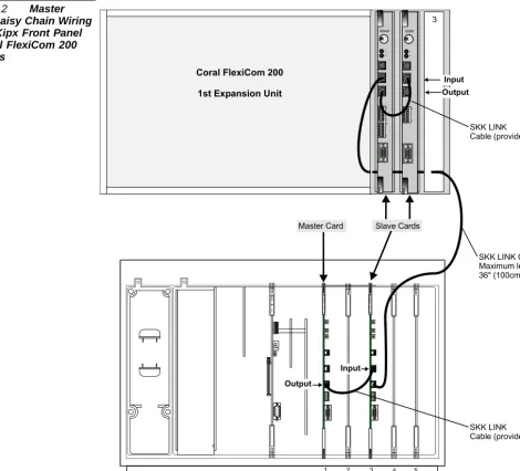
Figure 12: Master Slave Daisy Chain Wiring via SKKipx Front Panel of Coral FlexiCom 200 Systems ... 29
Figure 13: SKK Card SIO RS-232 Connection to Serial Port on Workstation ... 30
Figure 14: SKK Card SIO RS-232 COM settings Window... 31
Figure 15: SKK Card RJ-45 RS-232 Connection to Serial Port on Workstation... 32
Figure 16: SKK Card RJ-45 RS-232 COM Settings Window... 33
Figure 17: Boot Menu ... 35
Figure 18: Send File Window... 35
Figure 19: Xmodem file send for SVC Window ... 36
Figure 29: 8SKK and 16SKK Card to RBS Wiring via MDF ... 47
Figure 30: 8SKKipx Card to RBS Wiring ... 48
Figure 31: Typical FlexAir System Configuration with Repeaters... 50
Figure 32: Cluster including One RBS Unit with the Maximum Number of Repeaters ... 51
Figure 33: Front View of Repeater... 53
Figure 34: Rear Panel of Repeater unit ... 54
Figure 35: Repeater Configuration Connection ... 55
Figure 36: Service Tool Communications Tab... 57
Figure 37: Service Tool Repeater Tab... 58
Figure 38: Repeater Power Supply Connection ... 59
Figure 39: WinSio Main Window... 64
Figure 40: COM Port Selection Window... 64
Figure 41: Active WinSio Window... 65
Figure 42: Card Number Dialog Box... 65
Figure 43: Multilink Output... 66
Figure 44: Card Definition Via Program Interface... 67
Figure 45: Card Definition Via Program Interface... 68
Figure 46: WinSio Reset Message ... 70
Figure 47: Cable Delay Measurement Output ... 70
Figure 48: Cable Delay Measurement Via the Program Interface ... 71
Figure 49: Cable Delay Measurement Via the Program Interface ... 71
Figure 50: Cable Delay Measurement for the Entire FlexAir System via Master Card... 72
Figure 51: FlexAir Handset Units... 73
Figure 52: Battery Charger and AC Adaptor... 74
Figure 53: Battery Docking Station and AC Adaptor ... 74
Figure 54: Rear Panel of Handset Unit... 77
Figure 55: RSSI and Q Measurements... 87
Figure 56: Map of Typical Customer Site ... 94
List of Tables
Table 1: CNF Card Installation into Coral Systems ... 8
Table 2: 8/16 SKK Front Panel Card Functions... 17
Table 3: 8/16 SKK Card Component Side Functions ... 17
Table 4: 8SKKipx Top Panel Card Functions ... 20
Table 5: SKK Front Panel Card Indicator Status ... 21
Table 6: SKK Catalog Numbers... 22
Table 7: DIP Switch Configuration... 22
Table 8: SKK Card SIO RS-232 Connection to Serial Port on Workstation ... 30
Table 9: SKK Card RJ-45 RS-232 Connection to Serial Port on Workstation ... 32
Table 10: Connections between the SKK Card and the Workstation for Software Upgrade ... 34
Table 11: RBS Types ... 38
Table 12: RBS Red Indicator Status... 40
Table 13: Repeater Types ... 52
Table 14: Repeater Red Indicator Status ... 54
Table 15: FlexAir Handset Charger and Programming Accessories ... 75
Table 16: Card Status Messages ... 81
Table 17: Form for Handset Programming ... 85
Table 18: Handset and RBS Reception Measurement... 87
Table 19: SKK Card and RBS Locations ... 92
1
About this Manual
1
1
The FlexAir Installation Guide and Hardware Reference Manual is designed for field use by Coral system service personnel. It provides all the necessary information for successful installation and maintenance of the FlexAir wireless systems. This manual describes how to install the FlexAir system. The FlexAir system is designed to be installed into existing Coral systems. Technicians installing the FlexAir must be familiar with Coral systems. A brief summary of each chapter can be found in the table below.
1
Document Description
Where is it? What is it about? When to use it?
Chapter 2 About the Coral FlexAir System To learn about:
• The Coral FlexAir system • System terminology • Installation steps • System planning • RBS placement • Recommendations
• SKK and RBS interconnections
Chapter 3 SKK Wireless Station Interface Card •To learn /To install SKK cards into slots and set card jumper straps
• To upgrade the SKK software
Chapter 4 RBS Radio Base Station •To learn /To mount RBS, indoors or outdoors
Ab
out this Manu
al
1
1
For further information about the FlexAir system not covered by this manual, refer to the following documentation:
2
Related Documentation
Subject Manual
General Description Coral FlexiCom and IPx Product Description
8SKK and 16SKK cards Connections to MDF and RBS
•Chapter 5, Coral Installation Manual (see below)
SKK card installation guidelines • Chapter 2, Coral Service and Peripheral Cards Installation Manual
Coral Installation and Hardware Reference Manual
•Coral FlexiCom 200 Base Unit •Coral FlexiCom 200 Expansion Unit •Coral FlexiCom 300, 400, 5000 •Coral FlexiCom 6000
•Coral IPx 500 •Coral IPx 800 •Coral IPx 3000 •Coral IPx 4000
Installation and Hardware Reference Manual
Program Interface (Coral database) Program Interface and Database Reference Manual
Handset Operation Handset User’s Guide (included in the package)
RBS Operation DECT Base Station (RFP) - User’s Guide (included in the package)
Repeater Operation Repeater User’s Guide (included in the package)
Alarm Function Contact the manufacturer*
External Antenna Contact the manufacturer
11
Indicates important information demanding special attention.
Tips:
Advice that makes it easier to follow the steps of a procedure.
NOTES:
A page that is intentionally left blank. It may be used for the readers notes.
3
Special Symbols Used in this Manual
There is a danger to life or a risk of personal injury.
Ab
out this Manu
al
1
2
About the Coral FlexAir System
The FlexAIR Wireless is a communication system that allows portable handsets to be integrated within the Coral system. The wireless handsets provide most of the functions supported by standard wired keysets (FlexSets). This chapter provides a general description of the FlexAIR Wireless PABX and specific instructions for carrying out complete installation in the field.
2
2
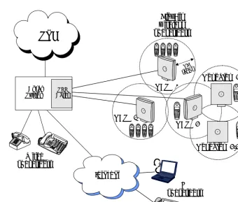
A typical FlexAir configuration, shown in Figure 1, includes a number of the following
components, in addition to the Coral platform:
SKK cards (8SKK, 16SKK, and 8SKKipx)
RBS - Radio Base Stations (antennas) and optional repeaters
Portable handsets and accessories
Figure 1 Typical System Configuration
1
FlexAir Wireless Configuration
RF radius
RBS #1
Coral
System CardsSKK
FlexAir wireless subscribers
PSTN
9 8 < <OK R123
5
ALT 4 6 789
0 9 8 < <OK R
123
5
A LT 4 6 789
0 9 8 < <OK R
123
5
ALT 4 6 789
0 9 8 < <OK R
123
5
ALT 4 6 789
0
<
About the Coral FlexAir System
2
222
Wireless Bands
The FlexAir Wireless System supports two wireless bands, allowing operation in various countries and regions. Supported wireless bands are:
ETSI DECT (1880-1900 MHz band), referred to as DECT
ISM (2418-2457 MHz band), referred to as ISM
The wireless band used by a FlexAir Wireless System is determined by the RBS units and wireless handsets ordered with the system. The SKK cards are not affected by the opening frequency.
Station Key Interface (SKK) Card
The SKK card is a Coral I/O peripheral card that provides up to sixteen (8SKK cards up to eight) digital ports for connection to RBS units. The SKK card can be ordered in
a number of configurations. Refer to Table 6, on page 22 for a list of the various card
types.
Radio Base Station (RBS)
The RBS is a compact device that contains RF circuitry and antennas. The main function of the RBS is to provide communication of audio and data signals between the mobile handsets and the Coral system via the SKK card. FlexAir supports up to four simultaneous calls per RBS unit.
Repeaters
The repeater extends the coverage area of an existing RBS unit without increasing the number of channels over the extended area. Repeaters are useful for applications where there are few additional subscribers over the extended area and the number of channels provided by the RBS can support all of the subscribers within the entire area.
External Antenna
An optional, external antenna can be attached to each RBS unit and repeater to extend its coverage area. The external antenna is not within the scope of this manual.
Portable Handset (T-304, T-402, T-404, T-408)
The mobile handset is a lightweight, ergonomically designed wireless unit that
Each handset is a portable unit that can be ordered to operate with either the DECT GAP standard or the ISM standard.
The portable unit is designed to provide the subscriber with most of the features available for a wired Coral FlexSet, in addition to its roaming and handover capabilities.
Roaming and Handover
Roaming refers to the ability to move between the coverage areas of different RBS units
while still being able to make and receive calls. Handover refers to the ability to move
between the coverage areas of different RBS units while talking, without interruptions in the conversation. FlexAir systems with clusters do not support handover; roaming between clusters includes a 30 second delay.
Clusters
A single SKK master card or a combination of one master card and its SKK slave cards is defined as one SKK cluster. Every cluster can consist of up to 8 SKK cards daisy chained together enabling a maximum of 128 Radio Base Stations (RBS) for a FlexAir cluster. An SKK cluster can also be installed in a Coral remote shelf. A Coral system supports up to eight clusters.
Clusters enable customer separation by supporting separate wireless systems within the same Coral system. Although clusters are effectively separate wireless systems, handsets can be subscribed to more than one cluster.
Coral Hardware Requirements for 3-way Conference Calls
About the Coral FlexAir System
2
Table 1 CNF Card Installation into Coral Systems
*For a CNF card, in the Card List (Route: CLIS) branch of the PI database, define the CNF card as C3WAY card type in the P_TYPE field. For further information refer to
page 80, Card List (Route: CLIS).
System Requirement
Coral FlexiCom 200 Base Unit CNSsl (single card only) Coral FlexiCom 300, 400, 5000, 6000
CNF* or 8DRCF Coral IPx 800, 3000, 4000
2
The Installation procedure for the FlexAir system includes the following steps:
Site survey, including planning and placement of RBS units and an RF site survey.
SKK Card Installation, including jumper configuration and installation of SKK
cards into the Coral universal I/O card slots
RBS installation, including mounting the RBS indoors and/or outdoors
External I/O connections, including all connections from the RBS units to the SKK
cards and the connections between SKK cards
Repeater installation, including mounting and installing the repeater and
synchronizing it to an RBS unit
SKK card configuration including cable delay measurement
Wireless handset configuration and setup, including handset subscription,
programming, and charging
PI database programming, including all FlexAir parameters that need to be
programmed within the Coral system
About the Coral FlexAir System
2
2
System Planning
A well planned Coral FlexAir Wireless system should start with an RF coverage site survey. A site survey is designed to determine the optimal location for RBS units and the amount of wireless voice traffic to be supported by the system (i.e., how many wireless handsets can maintain voice conversations at the same time, in any given area).
Due to the unexpected nature of RF propagation in an indoor environment, an actual on-site test must be performed before the installation is complete. While an extensive guide to effective RF coverage planning is outside the scope of this manual, the following points should be taken into consideration when planning the site, prior to RBS installation:
The RBS provides typical RF coverage of up to 150 feet (50 meters) in a typical
indoor office environment and up to 450 feet (150 meters) in an open area (line-of-site), extending in all directions from the RBS. The exact coverage range depends on the building architecture and wall material.
A single RBS unit provides up to four voice conversations simultaneously (on four
wireless handsets).
A Coral FlexAir Wireless system can support up to eight clusters.
A maximum of eight 8SKK or 16SKK cards can be installed per cluster.
A Coral FlexAir Wireless system can support a maximum of thirty-two 8SKK or
8SKKipx cards.
A Coral FlexAir Wireless system can support a maximum of sixteen 16SKK cards.
A Coral FlexAir Wireless system can support a maximum of 1535 portable
handsets. The actual number of stations is defined in the SIZES branch of the PI.
The RBS coverage can be extended by an additional four repeaters (without
increasing the number of channels).
The maximum number of RBS units per cluster is 128. The combined maximum
number of RBS units and repeaters per cluster is 256. If more than 128 repeaters are installed within a cluster, the number of RBS units that can be installed is reduced by the same amount.
The maximum number of RBS units per FlexAir system is 256. The combined
maximum number of RBS units and repeaters per FlexAir system is 2048.
Handset roaming and handover: wireless handsets can move between coverage
areas of different RBS units while receiving continuous service and maintaining conversations in progress. There is no handover between clusters.
For efficient handover of conversations between RBS units, deploy the RBS units
with wide overlap between them (i.e., plan for some areas to be covered by more
than one RBS. Repeaters can be used to increase the coverage). Overlaps are necessary, since handover requests can generate increased call traffic in certain areas. A good example may be a cafeteria during lunch hour where temporary concentrations of wireless handsets may occur. The overlap carries the excess call load to adjacent RBS to provide uninterrupted services to subscribers.
Typically, installations such as office buildings, hotels and hospitals should be
equipped with RBS units on several floors to create uniform and complete RF coverage.
Open areas can be covered with a sparse network of RBS units. In such
applications, the RBS units cover an extended range due to the extended line-of-sight RF propagation capability.
The SKK cards can reside in both remote and host FlexLITE shelves. This means
that FlexAir users can communicate with each other from different geographical locations that are up to 21 miles (35 km) apart.
Site Survey
Due to the complex nature of RF propagation in an indoor environment, the actual number of RBS units and their placement should be tailored to the specific building or location. This is done prior to the final wiring by using the FlexAir Wireless Site Survey Kit’s measurement capabilities and the handset’s RF indication facilities.
The site survey kit is not provided as standard issue and must be ordered separately. Contact your dealer for details.
1. Obtain a floor plan of the building and pay special attention to the following
details:
About the Coral FlexAir System
2
Traffic - number of potential users (for example, conference rooms or cafeteria)
3. Mark potential locations for RBS units by drawing an overlay grid pattern of lines
spaced by the average RBS range for the building in question according to:
RF coverage required by traffic
The number of potential users and the population expected in this area
Physical limitations: the possibility of placing an RBS in the desired location
and position.
Additional potential locations for installation of RBS units should be located in order to provide alternative options for the final placement.
4. Place the test RBS in the actual location and position (as close as possible) and plot
cell limits on the drawings by using the actual test measurement options.
5. Select the final placement according to the following guidelines:
Good coverage according to the number of simultaneous calls expected
Overlap coverage of about 10% to 20% especially in corridors or other passages
(where calls can be maintained while on the move)
Overlap coverage of all section in places where the expected traffic is high. The
overlapping RBS units should be installed close to each other. This will help in the coverage of the other sections
222
In multi-story buildings, RBS units may be installed on opposite sides of the floors
to take advantage of the floor-to-floor coverage. The coverage design cannot rely entirely on floor-to-floor propagation; each case must be verified due to variations in local attenuation patterns.
If the building contains a central open space area with windows to the other areas,
RBS units may be installed in this open space to provide a good coverage for the rooms in the inner circle on all floors (e.g. hotels).
If an RBS hangs vertically on a wall, the RF coverage in front of the RBS units is
twice as large as the coverage at the rear. When an RBS is installed on the outside of an outer wall, the RF coverage behind it is strongly attenuated by the wall.
RBS units should not be installed near large metallic objects.
Reinforced concrete structures have a high attenuation factor inside the building.
They decrease the RF coverage range of the RBS units and therefore requires a higher number of RBS units in the building. Lighter types of construction require fewer RBS units since attenuation figures are considerably lower.
About the Coral FlexAir System
2
222
2
Connections from the SKK Cards to the RBS
Connections between the RBS and the SKK card are made as follows: (see page 47,
External Connections)
8SKKipx - via the top panel connections
8SKK and 16SKK - via the MDF
Cable Length between SKK Card and RBS Unit
The RBS is designed to operate over line distances using internal power supplied by the Coral SKK card. The maximum line length used to connect the Coral main system to the RBS is 1500m (4500ft).
Communication between an RBS unit and a synchronized repeater is wireless and requires no cable connection.
2
rd
3
SKK
Wireless Station Interface Card
3
33
Inspect for Damage
1. Inspect the shipping carton for evidence of physical damage or mishandling prior
to opening.
2. Inspect all parts for damage.
3. Report any damage to the carrier immediately.
4. If it is necessary to make a damage claim for the carrier, do not move the shipping
carton until it has been examined by a representative of the carrier.
5. Dispose of empty cartons in accordance with local regulations.
Unpacking the Shipping Container
The following items should be present in every box containing an SKK card:
One SKK card
One SKK LINK cable (required for SKK-slave cards only). See page 27, SKK LINK
Input/Output Wiring Connections for a description of cables.
3
SKK W
ir
eless S
tation I
nterface Ca
rd
3
3
3
The SKK is a Coral peripheral I/O interface card that provides a number of digital ports for connection to RBS units.
The main functions of the SKK card are:
Handling communications with the Coral voice and control buses (via CPU 1)
Handling communications with the RBS units, including voice channels,
synchronization and data control (via CPU 2)
Front panel diagnostic indicators display the connection status between the SKK card and the RBS. The system diagnostic indicator displays whether the card has been
properly accepted by the Coral system. For more information, see page 21, LED
Indicators.
I/O connections to the SKK card can be made via the MDF (Coral IPx 800, 3000, 4000, and Coral FlexiCom 300, 400, 5000, 6000) or via RJ-45 connectors located on the top
panel (Coral FlexiCom 200 and Coral IPx 500). For more information, see page 47,
External Connections.
There are two card types: Type A includes DIP switches. Type B includes jumpers. Additional configuration options are determined either by setting the jumpers or DIP
switches. For more information, see page 22, Setting the Card to Boot or Normal Mode.
33
A Coral FlexAir cluster can be either a single card cluster or a multi-card cluster. In a multi-card cluster, SKK cards operate in one of two configuration options: the SKK slave card or the SKK master card. This configuration defines whether the SKK card acts as master or slave as well as how many slaves are attached to it.
SKK slave cards must be daisy-chained to the SKK-Master during installation. This
procedure is described on page 27, SKK LINK Input/Output Wiring Connections.
If there is only one SKK card in the cluster, it will automatically be configured as a
master card.
If there are several SKK cards in the cluster, the first one will appear as a master
and the rest of the SKK cards will appear as slaves.
It is possible to install up to eight SKK master cards.
2
SKK Card Description
rd
3The 8SKK and 16SKK cards are illustrated in Figure 2 and Figure 3.
The 8SKKipx card is illustrated in Figure 4.
The 8SKKipx card is installed in Coral FlexiCom 200 and Coral IPx 500 systems.
The SKK card front panels provide the following interface ports and diagnostic indicators:
Table 2 8/16 SKK Front Panel Card Functions
4
SKK Card Layout, Front, and Top Panel Features
Function What is it for?
Card ejectors Two ejectors (on the top and bottom of the front panel) used to
remove the card from the cage or shelf System Diagnostic
indicator (red)
Used to indicate whether or not the card is functional. See
page 21, LED Indicators. CPU #1
CPU #2
indicators (green)
Used to indicate whether the card software is functional CPU #1 - Application CPU (interfaces with the Coral) CPU #2 - DECT/KGAP CPU (interfaces with the RBS) See page 21, LED Indicators.
RJ-11 connector marked RBS 0
Used for debugging purposes by qualified technician authorized by the manufacturer
Input/output RJ-45 Connectors
Used to link all SKK cluster cards together in a daisy chain link. See page 27, SKK LINK Input/Output Wiring Connections.
RBS DIP switches Used to configure which RBS units are connected (left) and
which RBS units are not connected (right). See page 23, RBS
Configuration (RBS 0-7, 8-15). Indicators (adjacent to
RBS DIP switches)
Used to indicate a problem (red) or an inactive RBS unit (blank), or an active RBS unit (green). See page 21, LED
Indicators.
SKK W
ir
eless S
tation I
nterface Ca
rd
3
Figure 2 8SKK Card
8SKK
12
34
56
7
8
RBS0
Not Used
INPUT OUTPUT
SIO RS-232
For Application Upgrade Reset
Button
0 ON
OFF7 1 2
RBS 0 - 7
DIP switches and indicators
SKK
LINK
System diagnostic CPU
1 2 ON
Type A: Configuration DIP switches
rd
Figure 3 16SKK Card16SKK
123
456
78
12
34
56
7
8
INPUT
S
KK LINK
OUTPUT
SIO RS-232
For Application Upgrade Reset Button
1 2 RBS0
Not Used
RBS 0 - 15
DIP switches and indicators
0
7 8
15
System diagnostic CPU
ON
OFF
ON
Type B: Configuration jumpers 1 2
ON
SKK W
ir
eless S
tation I
nterface Ca
rd
3
33333The 8SKKipx card top panel provides the following interface ports.
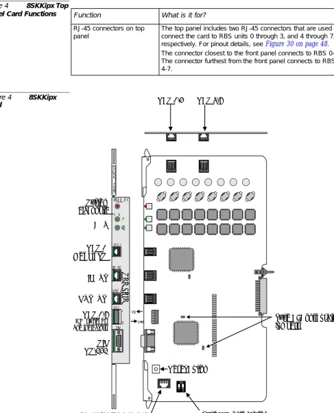
Table 4 8SKKipx Top Panel Card Functions
Figure 4 8SKKipx Card
Function What is it for?
RJ-45 connectors on top panel
The top panel includes two RJ-45 connectors that are used to connect the card to RBS units 0 through 3, and 4 through 7, respectively. For pinout details, see Figure 30on page 48. The connector closest to the front panel connects to RBS 0-3. The connector furthest from the front panel connects to RBS 4-7. 8 S K K I p x CPU RBS 0
Not Used
INPUT OUTPUT RBS 0-7 SIO RS-232For Application Upgrade
Reset Button RBS 0-3 RBS 4-7
INPUT OUTPUT RBS RBS 0 CPU SIO 0 7 DIP switches and indicators 1 2 8SKK ipx SKK LI N K System diagnostic ON
OFF Type B: Configuration
jumpers
12
ON
rd
33Figure 2, Figure 3 and Figure 4 illustrate the front panel of the SKK cards. Table 5lists the various indicators and their settings.
Table 5 SKK Front Panel Card Indicator Status
5
LED Indicators
Indicator State Description
System Diagnostic (Red)
OFF Functional
ON Malfunction
See Coral Service and Peripheral Cards
Installation Manual for further instructions and
Step 7on page 26.
Flashing Diagnostic test failed by circuitry on the card
CPU (Green)
Flashing rapidly Initializing
Flashing normally (1 second intervals)
Normal operation
Continuously ON Malfunction
Continuously OFF Malfunction
Flashing rapidly without stopping
Malfunction
RBS 0-7 RBS 8-15
OFF DIP switch is turned to the right (OFF) and the RBS
is inactive or not connected.
Red DIP switch is switched to the left (ON)
and RBS is not connected or not initializing
SKK W
ir
eless S
tation I
nterface Ca
rd
3
3
3
The SKK card can be ordered in a number of configurations, as listed in Table 6.
Table 6 SKK Catalog Numbers
33
DIP Switches (Type
A
)
For type A cards, there are two DIP switches (1 and 2) that are marked ON (above the upward configuration). Both DIP switches are set to ON (upward) during software upgrade. Both DIP switches are set to OFF (downward) during normal operation.
Table 7 DIP Switch Configuration
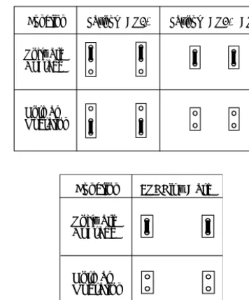
Jumpers (Type
B
)
For type B cards, there are two jumpers on each card component sidemarked:
"BOOT" on the 8SKK card (Figure 2) and the 16SKK card (Figure 3)
"ALT BOOT" on the 8SKKipx card (Figure 4)
The jumpers are used to configure the system either to Normal or Boot mode. The
Boot mode is configured during Software Upgrade. See page 34, SKK Card Software
Upgrade. Verify that both jumpers are set to Normal mode. See Figure 5 and Figure 6.
6
SKK Card Types
Card Maximum Number of RBS units
8SKK Card 8
8SKKipx Card 8
16SKK Card 16
7
Setting the Card to Boot or Normal Mode
Status 1 2
Boot ON ON
rd
Figure 5 JumperConfiguration for 8SKK and 16SKK Cards (Type B)
Figure 6 Jumper Configuration for 8SKKipx Cards (Type B)
3
33
The DIP switches, located on the front panel of the SKK card, are used to define which RBS unit is connected to the card.
For every active RBS, set the corresponding DIP switch to the left.
For every non-active or non-connected RBS, set the corresponding DIP switch to
the right.
If a non-active DIP switch is set to the left, its corresponding diagnostic indicator will be continuously ON (red).
Function Layout PCS2* Layout PCS3, PCS4
Software Upgrade
Normal Operation
8
RBS Configuration (RBS 0-7, 8-15)
Function 8SKKipx Card
Software Upgrade
SKK W
ir
eless S
tation I
nterface Ca
rd
3
333333
Each Coral system can support up to thirty-two 8SKK, 8SKKipx cards or sixteen 16SKK cards. The SKK LINK cable is 4” (10cm) long. Therefore, a maximum of two cards can be positioned on a Coral shelf between each SKK card. While it is advisable to position the cards of one cluster on a single shelf, they can be distributed over two shelves by connecting an SKK card on one shelf to an SKK card on another shelf with a locally fabricated SKK LINK cable that is up to 36” (100cm) long. For more
information, see page 27, SKK LINK Input/Output Wiring Connections.
The SKK cards can be installed in any one of the following card slots:
Coral IPx 500: 8SKKipx can be installed in any peripheral slot
Coral IPx 800, 3000 and 4000: 8SKK and 16SKK can be installed in any universal
I/O card slot
Coral FlexiCom 200: 8SKKipx can be installed in slots 1, 2 and 3
Coral FlexiCom 300, 400, 5000 and 6000: 8SKK and 16SKK can be installed in any
universal I/O card slot
Coral FlexLITE system: 8SKK and 16SKK can be installed in any universal I/O slot
in any local or remote peripheral shelf
Clusters
A single SKK master card or a combination of one master card and its SKK slave cards is defined as one SKK cluster. Every cluster can consist of up to 8 SKK cards daisy chained together enabling a maximum of 128 Radio Base Stations (RBS) for a FlexAir cluster. An SKK cluster can also be installed in a Coral remote shelf. A Coral system supports up to eight clusters.
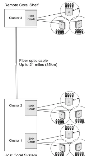
Integrating FlexAir and FlexLite Systems
Complete wireless coverage can be achieved for campus environments that are up to 21km (35m) apart. By integrating SKK cards within host and remote cabinets of Coral FlexLite systems, a FlexAir subscriber from one campus can communicate with
another subscriber from a different campus. See Figure 7.
rd
Figure 7 TypicalFlexAir System
Combined with a Remote FlexLITE Shelf
Cluster 2
Fiber optic cable
Up to 21 miles (35km)
SKK Cards 9 8 < <OK R
123
5
A LT
46 7809
FlexAIR 9 8 < <OK R
123
5
A L T
46 7809
FlexAIR
98
<
<OK
R
123
5
A LT
46 7809
FlexAIR 9 8 < <OK R
123
5
AL T
46 7809
Fle xAIR SKK Cards 9 8 < <OK R
1253
A LT
46 789
0 FlexAIR 9 8 < <OK R
1253
A L T
46 789
0 FlexAIR 98 < <OK R
1253
A LT
46 789
0 FlexAIR 9 8 < <OK R
1253
AL T
46 789
0
Fle xAIR
Remote Coral Shelf
SKK Cards 9 8 < <OK R
123
5
A LT
46 7809
FlexAIR 9 8 < <OK R
123
5
A L T
46 7809
FlexAIR
98
<
<OK
R
123
5
A LT
46 7809
FlexAIR 9 8 < <OK R
123
5
AL T
46 7809
Fle xAIR 9 8 < <OK R
1253
A L T
46 789
0 Fle xAIR 9 8 < <OK R
1253
AL T
46 789
0 FlexAIR 9 8 < <OK R
1253
AL T
46 789
0 FlexAIR 9 8 < <OK R
1253
A L T
46 789
0 FlexAIR 9 8 < <OK R
123
5
A L T
46 7809
FlexAIR 9 8 < <OK R
123
5
A LT
46 7809
FlexAIR 9 8 < <OK R
123
5
AL T
46 7809
FlexAIR 9 8 < <OK R
123
5
A LT
46 7809
FlexAIR
98
<
<OK
R
123
5
A L T
46 7089
FlexAIR 9 8 < <OK R
123
5
A L T
46 7809
FlexAIR 9 8 < <OK R
123
5
A LT
46 7809
FlexAIR
98
<
<OK
R
123
5
AL T
46 7809
FlexAIR 9 8 < <OK R
1253
AL T
46 789
0 FlexAIR 98 < <OK R
1253
A L T
46 789
0 FlexAIR 9 8 < <OK R
1253
A L T
46 789
0 FlexAIR 9 8 < <OK R
1253
A LT
46 789
0
Fle xAIR
SKK W
ir
eless S
tation I
nterface Ca
rd
3
3
Insert the SKK cards in the cards cage as follows:
1. Connect the static dissipating wrist strap connector to the cage and put on the
strap.
2. Prior to inserting the SKK card into the Coral card cage, verify that its jumpers are
configured for “Normal Operation” as described on page 22, Setting the Card to Boot
or Normal Mode.
3. Select a slot for the SKK card as defined on page 24, SKK Card Distribution among
Shelves.
4. Grasp the card with both hands, with your fingers on the edge of the card near
the front panel, and your thumbs against the ejectors at the top and bottom of the front panel. Verify that the card is oriented correctly (the red diagnostic indicator on front panel is positioned near the top of the card).
5. Align the edges of the circuit card with the card edge guides in the card cage, and
gently slide the card straight into the card slot. A slight resistance will be felt as the multi-pin connectors on the circuit card meet mating connectors on the backplane and engage.
6. Push against the ejectors until the front panel of the card is flush with the front
frame of the card cage.
7. Verify that the system diagnostic indicator on the front panel lights up and then
extinguishes. This indicator turns on to indicate card initialization and then goes
out upon successful completion. If the indicator remains lit or flashes, see Coral
10 Inserting the SKK Cards into the Coral Shelf or Cage
• Circuit cards contain static-sensitive circuitry and may be damaged or destroyed by electro-static discharge (ESD).
• Always wear the static dissipating wrist strap connected to the system cabinet or card cage while handling circuit cards.
• Hold cards by their edges and avoid touching contact surfaces. Handle with care and do not drop.
rd
33
SKK cards within each cluster are “daisy-chain” linked together during installation in
the following manner: the two SKK front panel RJ-45 jacks labeled Input and Output
are used to link the cards. Each SKK card is supplied with one SKK LINK cable. The output connector of the master card is connected by a cable to the input connector of a slave card. The output connector of the slave card is connected to the input connector of the next slave card, and so on.
The SKK LINK cable provided by the manufacturer is 4” (10cm) long. See Figure 8. If
the SKK cards of a cluster need to be distributed over two shelves, one 36” (100cm)
SKK LINK cable can be fabricated by the customer to facilitate this connection. The pinout for the SKK LINK cable is displayed in
Figure 10.
The SKK LINK cable provided by the manufacturer is designed to interconnect the SKK cards with minimal attenuation. Longer cables will increase the attenuation and could prevent the system from functioning properly. Do not install more than one locally fabricated SKK LINK cable. If a locally fabricated SKK LINK cable is installed, verify that it is no more than 36” (100cm) long.
Figure 8 SKK LINK Cable Length (Provided)
For Coral IPx 800, 3000, 4000, 6000, FlexiCom 300, 400, and 5000 installation,see
Figure 11for 8SKK and 16SKK card master-slave wiring.
11 SKK LINK Input/Output Wiring Connections
4" (10cm) max
SKK W
ir
eless S
tation I
nterface Ca
rd
3
Recognizing an RJ-45 Straight SKK LINK Cable
You can recognize a straight cable by comparing the two modular ends of the cable. Hold the cables side-by-side with the latch facing away from you. The straight cable wire colors are in the same sequence at both ends of the cable.
Figure 9 SKK LINK Cable Identification
Figure 10 SKK LINK Cable Pinout
rd
Figure 12 MasterSlave Daisy Chain Wiring via SKKipx Front Panel of Coral FlexiCom 200 Systems
Coral FlexiCom 200
1st Expansion Unit
3 M C P -IP s l KB0
1 2 3 4 5
Slave Cards Master Card 1 0 2 7 8SKK 123 45678 1 0 0 2 7 7 16SKK 1234 5678 12345 678 8 S K K s l 8 S K K s l Output Input Output Input
SKK W
ir
eless S
tation I
nterface Ca
rd
3
3 3The SIO (Serial Input Output) data terminal port is used to connect the RS-232 serial cable for CPU #1 and CPU #2 card software upgrade and to configure the card. The serial interface of the SIO programming port on the SKK front panel conforms to the EIA RS-232 specification. It is wired as a Data Terminal Equipment (DTE) device using a popular 9-pin, male, D-type connector. The interface allows connection of a common, asynchronous, ASCII data terminal, or personal computer for programming
the various features of the Coral FlexAir system. Figure 13 illustrates the cable
connection to serial port on workstation. Table 8 lists the pin numbers.
3 Figure 13 SKK Card SIO RS-232 Connection to Serial Port on Workstation
Table 8 SKK Card SIO RS-232 Connection to Serial Port on Workstation
12 SIO RS-232 Front Panel Programming Port
Workstation RS-232
DB-9 Female DB-9 FemaleCard RS-232
1 2 3 4 5 6 7 8 9 1 2 3 4 5 6 7 8 9 1 2 3 4 5 6 7 8 9 1 2 3 4 5 6 7 8 9 NC NC
Workstation Pin # Card Pin #
1,6 4 2 3 3 2 4 1,6 5 5 7 8 8 7
rd
SIO RS-232 COM Port Settings
The default SIO port settings are as follows:
Baud rate - 115200
Parity - none
Data bit - 8
Stop bits - 1
To change the default setting:
1. In the WinSio application, select Connection and then Settings. The COM
Settings window opens.
Figure 14 SKK Card SIO RS-232 COM settings Window
2. Make the changes as required and press OK.
SKK W
ir
eless S
tation I
nterface Ca
rd
3
3 3Data terminal port, used to connect RS-232 serial cable for CPU #1 card software upgrade.
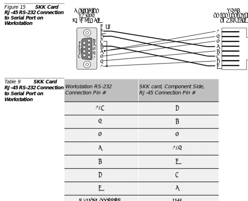
The serial interface of the RJ-45 programming port on the SKK component side conforms to the EIA RS-232 specification. It is wired as a Data Terminal Equipment (DTE) device using an RJ-45 8-pin connector. The interface allows connection of a common, asynchronous, ASCII data terminal, or personal computer for programming
the various features of the Coral FlexAir system. Figure 15 illustrates the cable
connection to serial port on workstation. Table 9 lists the pin numbers.
Figure 15 SKK Card RJ-45 RS-232 Connection to Serial Port on
Workstation
Table 9 SKK Card RJ-45 RS-232 Connection to Serial Port on
Workstation
13 RJ-45 RS-232 Component Side Programming Port
8 9 NC Workstation RS-232 DB-9 Female RJ-45 on component side
of SKK card
7 6 5 4 3 2 1 1 2 3 4 5 6 7 8 1 2 3 4 5 6 7 8 9 Workstation RS-232 Connection Pin #
SKK card, Component Side, RJ-45 Connection Pin #
1, 6 7
2 5
3 3
4 1, 2
5 8
7 6
8 4
rd
RJ-45 RS-232 COM Port Settings
The default RJ-45 port settings are as follows:
Baud rate - 57600
Parity - none
Data bit - 8
Stop bits - 1
To change the default setting:
1. In the WinSio application, select Connection and then Settings. The COM
Settings window opens.
Figure 16 SKK Card RJ-45 RS-232 COM Settings Window
SKK W
ir
eless S
tation I
nterface Ca
rd
3
3
The SKK card houses two CPUs (Central Processing Units):
CPU #1 the application CPU, which interfaces with the Coral main processor
CPU #2 the DECT CPU, which interfaces with the handsets and the RBS units
Periodically the software on these CPUs needs to be upgraded. Both CPUs can be upgraded by connecting a standard null modem cable between the serial port of a workstation and the RS-232 connector on the front panel of the SKK card. In addition, the application software can be upgraded using an RS-232 to RJ-45 cable connected between a workstation and the RJ-45 connection on the component side of the SKK
card. See page 30, SIO RS-232 Front Panel Programming Port and page 32, RJ-45 RS-232
Component Side Programming Port. This cable is not provided by the manufacturer.
Table 10 Connections between the SKK Card and the Workstation for Software Upgrade
Tips:
Using two workstations, you can upgrade CPU#1 and CPU#2
simultaneously by connecting one workstation to the SIO RS-232 connector on the front panel, of the SKK card and the other workstation to the RJ-45 connector on the component side of the SKK card.
The following procedure is identical for both Application CPU#1 upgrade and DECT CPU#2 upgrade. The order of upgrading is not important. After upgrading the first CPU, repeat the entire procedure for the other CPU.
1. Change the Jumper to boot mode, see page 22, Setting the Card to Boot or Normal
Mode.
2. Make one of the following connections between the SKK card and the
workstation(s) as necessary. See Table 10.
For SIO, verify that the SIO RS-232 cable is connected between the connector
marked asSIOon the SKK card front panel and the COM port on the laptop.
The default port is COM1. To change to COM2, activate the program with a
specific note SIO.EXE/C2. See page 30, SIO RS-232 Front Panel Programming
Port.
14 SKK Card Software Upgrade
Software Can it be upgraded using the SIO RS-232 connector (described on page 30)?
Can it be upgraded using the RJ-45 connector (described on page 32)?
CPU #1 Application Yes Yes
rd
For RJ-45, verify that the RJ-45 RS-232 cable is connected between the connector
on the SKK card component side and the COM port on the laptop. See page 32,
RJ-45 RS-232 Component Side Programming Port.
3. Press the reset buttonon the card or remove and insert the SKK card in the Coral
system. A boot menu should appear on the terminal as shown in Figure 17.
Figure 17 Boot Menu
4. In the command line prompt (>>) type Xand then press Enter. The following
prompt appears: CCCCCCC...>>. Select the designated protocol from the
terminal.
5. From Transfer, select Send File from HyperTerminal.
6. Click the Browsebutton, and select one of the following:
ECI-SKK_APP_FLASH_VER(X).bin
(Application CPU#1), or ECI-SKK_DECT_FLASH_VER(X).bin
(DECT CPU#2)SKK W
ir
eless S
tation I
nterface Ca
rd
3
Figure 19 Xmodem file send for SVC Window
9. When it has finished loading, the HyperTerminal displays the following:
Xmodem OK... Received xxxxxx bytesas shown in Figure 20. Wait for the
Send operation to finish and the >> prompt to displays. See Figure 20.
From the SKK menu, select A1to burn an image to the runtime area in flash (A1 is
case-sensitive). While the image is burning, the following progress message will be displayed:
Burning RAM image to flash
After the burning process is completed the following message will appear:
Burning Complete. Card will now restart
Figure 20 Burning Complete Message
10. When the flash programming process is complete, reconfigure the jumper position
to “run” mode. See Figure 5 and Figure 6. Reset the card.
4
RBS
Radio Base Station
44
Inspect for Damage
1. Inspect the shipping carton for evidence of physical damage or mishandling prior
to opening.
2. Inspect all parts for damage.
3. Report any damage to the carrier immediately.
4. If it is necessary to make a damage claim for the carrier, do not move the shipping
carton until it has been examined by a representative of the carrier.
5. Dispose of empty cartons in accordance with local regulations.
Unpacking the Shipping Container
The following items should be present in every box containing an RBS:
One (1) RBS unit
One (1) bracket template
Two (2) mounting screws
Two (2) anchors (wall plugs)
For outdoor installations, an outdoor enclosure box for the RBS should be supplied,
RBS
Radio Ba
se S
tatio
n
4
4
RBS provides RF Channels to Portable Handsets
The RBS is a compact device that contains RF circuitry and transmit/receive antennas. The main function of the RBS is to provide audio and data communication between the portable handsets and the Coral via the SKK card. The RBS supports four RF channels.
The RBS is also sometimes known as the RFP (Radio Fixed Part).
The RF communication is provided according to the band standard at the site:
RBS-DECT provides four RF channels of 1.88 GHz, DECT standard, used in
Europe, Australia and South America.
RBS-ISM provides four RF channels of the 2.4 GHz band used in the USA.
The RBS Can be Installed Wherever It Fits Best
The RBS can be installed either indoors or outdoors.
Indoors - the RBS is suitable for mounting indoors on a wall, only. See page 41,
RBS Indoor Installation.
Outdoors - the RBS can be placed in a weatherproof, environmentally protected
unit suitable for installation on external walls, poles etc. See page 43, RBS Outdoor
Installation.
RBS Distance from the Coral
The Coral system supplies power to the RBS up to 1,500m (4,500ft) cable length. To
increase the coverage, it is possible to connect a repeater. See page 49, FlexAir Repeaters.
RBS Traffic Support
An RBS supports four (4) RF channels simultaneously. All channels are used for both audio conversation detectable by portable handsets.
Table 11 RBS Types
2
RBS Description
Part
4
The RBS unit includes the following components:
Front Panel
An indicator on the front panel that displays the operational status of the RBS. See
Figure 21 for the front view of the RBS unit. See Table 12 for a description of the RBS indicator status.
Rear Panel
The rear panel includes (See Figure 22):
A knock-out opening for connecting an external antenna (not in the scope of this
manual)
An RJ-11 6-pin jack used to connect the communication wire pair that is routed to
the SKK card. Pins 3 and 4 are used.
Four plastic hooks designed to be inserted into the mounting template.
Figure 21 Front View of RBS
3
RBS Appearance and Components
RBS
Radio Ba
se S
tatio
n
4
RBS Diagnostic Indicators
The RBS front panel has one red indicator describing the RBS operational status. See Table 12.
Table 12 RBS Red Indicator Status
RJ-11 Jack
The RJ-11 jack houses the cable connector from the SKK card. Figure 22 displays the
pinout between the RBS unit and the SKK card. For a connection description, see
Figure 29 and Figure 30on page 48.
Bracket Template
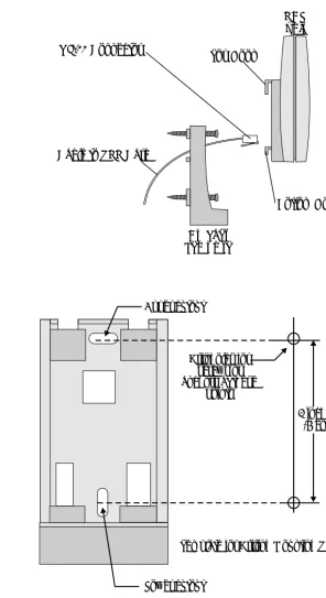
The bracket template includes (see Figure 23):
Two mounting holes that allow it to be affixed to the wall or to the outdoor
enclosure box.
Four openings designed to mate with the four plastic hooks on the rear panel of
the RBS.
The connector cutout, for routing the cable through the mounting template to the
rear panel of the RBS.
Figure 23 Bracket Template Mounted onto the Wall
Status Description
OFF One or more of the following:
• SKK card removed
• SKK DIP switch switched OFF (to the right) • Cable disconnected
ON RBS is operating properly
Flashing Initializing
Connector Cutout
Upper Screw
Lower Screw
4
For best RF coverage, the RBS must be mounted vertically, on walls.
Installation RF Coverage
The RBS propagation pattern is extended in front of the RBS and diminished behind it.
To install the RBS indoors:
The FlexAir is easily wall mounted with the bracket template. Using the anchors and screws provided, mount the bracket template onto the wall as follows:
1. Place the bracket template on the wall in the spot where you wish to mount the
RBS.
2. Make a mark on the wall at the middle of the upper cutout and at the middle of
the lower cutout on the bracket, as indicated in Figure 25.
3. Use a small drill bit 0.197” (5mm) or smaller to drill two holes into the wall for the
4
RBS Indoor Installation
The RBS must not be installed at any other angle other than vertical. The RBS might not transmit or receive effectively if it is installed at an incline or is attached to the ceiling.
RBS
Radio Ba
se S
tatio
n
4
Figure 24 Cable Routed through the Bracket Template
Figure 25 Bracket Template
8. Connect the cable into the RJ-11 jack on the RBS. For a description of the RJ-11
pinout, see Figure 22.
9. Insert the plastic hooks on the rear panel of the RBS unit into the bracket template
and push the RBS down until it clicks into place. See Figure 24.
RBS unit
Cable to SKK Card
Bracket Template
RJ-11 Connector Top Hook
Bottom Hook
Drill holes for screws or anchors at these
points
Lower cutout
Template for Drilling Mounting Screws 2 inches
4
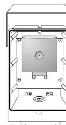
Outdoor installation requires an outdoor protective enclosure box in which the RBS is installed.
This box is designed to allow a great flexibility of installation place and position. It must be mounted vertically, on poles, walls, pipes, etc.
1. On the bottom of the protective rubber plug (positioned at the bottom of the
outside enclosure box). Cut a hole large enough to insert the cable routed from the MDF or SKK card.
2. Insert the cable through the rubber plug cut in the previous step.
3. Insert the cable through the mounting bracket. Do not mount the bracket onto the
outside enclosure box before routing the cable. See Figure 24.
4. Fasten the mounting bracket onto the inside surface of the enclosure box. See
Figure 23 and Figure 26.
Figure 26 Outdoor Enclosure Box without RBS
5
RBS Outdoor Installation
RBS
Radio Ba
se S
tatio
n
4
Figure 27 Outdoor Enclosure Box with RBS
7. Using the enclosure as a template, drill four 0.24” (6mm) holes into the wall.
8. Using the anchors and screws provided, mount the metal hook on the outside
wall.
Figure 28 RBS Enclosure Box Mounting onto Outside Wall
9. Mount the outdoor enclosure box onto the hook and fasten the bottom of the box
to the wall with the two screws provided.
Top screws and washers
Bottom screws
Metal hook
4
Verifying SKK Card Configuration
Verify that the RBS ports to be used have been enabled via the appropriate SKK card
DIP switches. Switch the DIP switches left or right accordingly. See page 23, RBS
Configuration (RBS 0-7, 8-15).
Connecting to the MDF or SKK
Perform the wiring procedure between the MDF or SKK card as described on page 14,
Connections Between the SKK Cards and the RBSandpage 47, External Connections.
Recording the Installation Information
After completing the installation of the RBS units, record the location of each RBS. See
Table 19, on page 92.
Checking the Indicators
Verify that the RBS indicator is continuously on, indicating that the RBS is
functional. See Figure 21on page 39.
Verify that the relevant SKK card DIP switch indicators are green, indicating that
every RBS unit is functional. See Table 5on page 21.
After installing the corresponding SKK card, it may take up to 15 minutes for the RBS indicator to light continuously and for the SKK DIP switch indicators to light green.
RBS
Radio Ba
se S
tatio
n
4
4
The SKK card provides power to its RBS units from the main Coral power supply. The power is supplied on the feed pair in phantom mode.
ecting
th
e SKK Car
d to the
RBS
5
External Connections
Connecting the SKK Card to the RBS
5
This section describes the instructions for connecting RBS to SKK cards. Connections
between the SKK card and the RBS are made via one pair of Category 4 Twisted
telephone cable or higher. These carry the digital connection transmit and receive signals. The maximum line length is 1500m (4500ft).
5
The 8SKK and 16SKK cards are connected to the RBS units via the MDF. Figure 29
shows the wiring between the MDF and the RBS and the pinout assignments for the
RBS RJ-11 connectors. See page 2, Related Documentation for Chapter 5 of the relevant
Coral system.
Figure 29 8SKK and 16SKK Card to RBS Wiring via MDF
5
1
Coral IPx 800, 3000, 4000 and FlexiCom 300, 400, 5000, 6000
2
Coral IPx 500 and FlexiCom 200 Installations
3Base Station RJ-11 Plug (male)
MDF
External Con
nectio
ns
Conn
ecting
th
e SKK Car
d to the
RBS
5
Figure 30 8SKKipx
Card to RBS Wiring RBS
3 RBS
2 RBS
1 RBS
0
1 2 3 4 5 6 7
8 87654321
8 S K K I p x
4,5 1,2 3,6 7,8 4,5 1,2 3,6 7,8
RBS 7 RBS
6 RBS
5 RBS
4
RJ-45 Connector RJ-45
Connector
RBS 0-3 RBS 4-7
6
FlexAir Repeaters
6
Inspect for Damage
1. Inspect the shipping carton for evidence of physical damage or mishandling prior
to opening.
2. Inspect all parts for damage.
3. Report any damage to the carrier immediately.
4. If it is necessary to make a damage claim for the carrier, do not move the shipping
carton until it has been examined by a representative of the carrier.
5. Dispose of empty cartons in accordance with local regulations.
Unpacking the Shipping Container
For indoor installations, the following items should be present in every box containing a repeater:
One (1) repeater unit
One (1) bracket template for indoor installation
Two (2) mounting screws
Two (2) anchors