SIMULATION OF FUZZY BASED MODULAR MULTILEVEL DC /DC
CONVERTER WITH FAULT BLOCKING CAPABILITY FOR HVDC
INTERCONNECTS
Dept. of Electrical and Electronics Engineering
Abstract- This paper presents the first dynamic model of the DC-MMC, a new class of modular multilevel single-stage dc/dc converters aptly suited for HVDC systems. DC-MMC, that can be deployed to interconnectHVDC networks of different or similar voltage levels. Its key features include bidirectional power flow, step-up and step-downoperation, and bidirectional fault blocking similar to a dc circuitbreaker. The kernel of the DC-MMC is a new class of bidirectionalsingle-stage dc/dc converters utilizing interleaved strings of cascaded submodules. A Fuzzy logic Controller is implemented for DC-MMC operation is analyzed and anopen loop voltage control strategy that ensures power balance ofeach sub module capacitor via circulating ac currents is proposed. MATLAB/Simulink software is used for to simulate the DC-MMC with the proposed control strategy.
Index Terms—Converters, dc-dc power conversion, HVDC converters, multilevel systems. Fuzzy Logic Controller
I. INTRODUCTION
The dc/ac modular multilevel converter (MMC) has gained widespread popularity due to its many operational advantages for high voltage and high power applications. It is particularly attractive for HVDC applications as large operating voltages are easily realized by stacking the necessary number of modular switching cells, referred to as submodules (SMs)[1]-[2]. However, MMC based dc/dc conversion has, to date, revolved around the use of two cascaded MMC structures in a dc/ac-ac/dc configuration. A new class of modular multilevel bidirectional dc/dc converters based on the MMC concept have recently been proposed. These converters, termed the DC-MMC, are able to achieve single-stage dc/dc conversion using series cascaded SMs. The traditional intermediate ac link is eliminated by exploiting circulating ac currents to maintain power balance of the SM capacitors. This new power transfer mechanism bears similarity to that recently described in other dc/dc topologies utilizing the concept of circulating ac power have
also recently emerged. Compared with two cascaded dc/ac MMCs, the DC-MMC is very appealing as a significant improvement in total SM utilization as well as reduced operating losses can be realized. The DC-MMC also offers advanced features such as buck/boost capability and dc circuit breaker capability. Although the prospect of HVDC-based grids offers many benefits, one of the principle challenges facing their widespread deployment is the interconnection of different dc networks and management of power flows between them. To accommodate both functions, bidirectional dc/dc converters can be dispatched (although other devices tailored for power flow control exist. By using dc/dc converters to adjust line voltages, or the voltage between different network segments, the power controllability within dc grids can be extended. Furthermore, formation of larger dc networks can be realized by utilizing dc/dc converters to mesh together smaller preexisting dc grid segments. However, due to the high voltage (i.e., hundreds of kilovolts) and high power (i.e., hundreds of megawatts) requirements, few dc/dc topologies are suitable for HVDC applications. The use of two cascaded dc/ac stages is costly and hinders overall conversion efficiency while transformer less dc/dc converters are typically not fully modular and can suffer from uncontrolled propagation of fault currents[15] due to external dc faults.
Due to its modular structure and many operational advantages, the well-known modular multilevel converter (MMC)has become a preferred solution for dc/ac conversion in various power system applications. The MMC is particularly attractive for use in HVDC transmission [11],where its scalable architecture enables large operating voltages to be realized by simply stacking the requisite number of submodules (SMs) in cascade. However, the main drawback of MMC-based dc/dc topologies is that they require two cascaded dc/ac conversion stages[11]. This is a relatively costly solution as each dc/ac stage must process the same input power, resulting in poor utilization of total installed SM rating. Moreover, the inherent need for an intermediate ac link and transformer rated for the full input power further adversely impacts the total cost as well as overall conversion efficiency.
POONAMALLIBALAJI,GAMPALASUMAN
Visvodaya
Institute
Of
Technology
and
Science,
Kavali,
SPSR
Nellore
District,
Andhra
Pradesh
State
,
India
This paper proposes a modular multilevel dc/dc converter termed as the DC-MMC, and that has the capability to interconnect HVDC networks of either different or similar voltage levels while simultaneously offering the promise of bidirectional fault blocking. The DC-MMC uses multiple interleaved strings of cascaded SMs to perform single-stage bidirectional dc/dc conversion, and is capable of both step-down and step-up operation. Elimination of the traditional intermediate ac link is achieved by exploiting circulating ac currents to maintain power balance of each SM capacitor. This new energy conversion process employs a power transfer mechanism first introduced in[15], which bears similarity to that recently described in[36]. A significant advantage of the DC-MMC is that a single converter structure can be utilized in place of two cascaded dc/ac converters. This offers a substantial improvement in utilization of total installed SM rating, as all SMs within the DC-MMC contribute to its overall dc power transfer capability. In addition, the flexibility to interconnect HVDC networks of similar voltages, as well as the capability for bidirectional fault blocking akin to a dc circuit breaker, make the proposed DC MMC an attractive device for deployment in future dc grids.
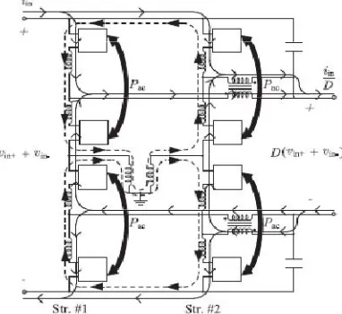
Fig. 1. Three-string DC-MMC architecture with input and output filtering: (a) circuit diagram (b) switching cell configurations for j th half-bridge SM (HB/SM) and j th full-bridge SM (FB/SM).
II. PROPOSED DC-MMC FOR HVDC INTERCONNECTS
A. Three-String Architecture
Fig. 1(a) shows the three-string architecture of the DC-MMC for deployment in bipolar HVDC networks. The DC-MMC performs single-stage dc/dc conversion by utilizing interleaved strings of cascaded SMs. Each string is comprised of two pairs of arms; each pair of arms consisting of an inner arm and an outer arm, where an arm is defined as a set of cascaded SMs. The arms of each string are series-stacked in symmetric relation about an associated midpoint, i.e., o1, o2, o3, with the inner arms flanked by the outer arms. Each inner arm and outer arm employs mhalf-bridge SMs (HB/SMs) and k full-bridge SMs (FB/SMs), respectively. Circuit configurations for the HB/SM and FB/SM switching cells are given in Fig. 1(b). Arm chokes La accommodate the switching action of the SMs. A path, enabled here by inductor Lr, links the strings together via their midpoints andserves to establish circulating ac currents required by the dc/dc conversion process. Input filtering for the DC-MMC is optionally provided by Lsand Cs . However, output filter element Lf is necessary to attenuate ac voltages present at the dc output nodes of each string. The magnetizing inductance Lf of each set of coupled inductors is suitable to provide the large impedance needed for attenuation of the ac output filter currents. Moreover, use of coupled inductors as shown ensures cancellation of dc flux within the core. Capacitors Cfare a practical consideration to sink high-frequency ac currents introduced by switching action of the SMs. The use of passive elements Lf and Cfis a relatively
low cost and simple implementation as compared to alternative active-filtering solutions. General sizing considerations for the output filters is provided in the Appendix.
In comparison to the three-phase dc/ac MMC, the three-string architecture in Fig. 1 shares a similar modular structure. As will become more apparent in subsequent sections, the three-string implementation of the proposed DC-MMC may be viewed as the three-phase dc/ac MMC structure adapted for single-stage dc/dc conversion. Unlike the recently proposed dc/dc converter in, which is formed by series-stacking two conventional three-phase dc/ac MMCs, the operation and control of Fig. 1 is fundamentally different from that of the dc/ac MMC.
B. Two-String Architecture
one of the strings, a two-string implementation is also possible as shown in Fig. 2. This architecture is the simplest multistring implementation of the DC-MMC. In general, an arbitrary number of strings can be interleaved. Note the ability to install a coupled inductor set at each dc output pole has been exploited due to the even number of interleaved strings. Consequently, this reduces insulation requirements on the output filter inductances as compared to Fig. 1. The two-string and three-string architectures have the same fundamental principle of operation as each string employs an identical dc/dc conversion process. For equal string designs, the two-string has 2/3 the output power rating of the three-string.
Fig: 2. Two-string DC-MMC architecture with input and output filtering.
C. Principle of Operation
In Figs. 1 and 2, the input network voltages vin+ and vin−can be unevenly split between the arms of each string. For example, arm voltages v1k (outer arm) and v1m (inner arm) can have unequal dc components that sum to vin+. The same applies to v_1m (inner arm) and v_1k (outer arm) with vin−. Division of vin+ and vin−as described is achieved by controlling the number and polarity of SM capacitors inserted along each string via switching action, where possible switching states for the j th HB/SM and FB/SM are vsmj= {0,+vcj } and vsmj= {0,−vcj ,+vcj}, respectively. The output network, represented by vout+ and vout−, is coupled across the inner arms of each string as shown. DCpower transfer between networks can be reversed by changing polarity of iin. Bidirectional dc power transfer is easily accommodated as the SMs inherently permit bidirectional current flow.The arrangement of HB/SMs and FB/SMs in Figs. 1 and 2 permits both step-up and step-down voltage level conversion for the DC-MMC. The voltage
conversion ratio D and its complementD’ are defined as
From (1) and (2) the operating modes of the DC-MMC are summarized:
1) step-down operation: 0 < D <1 and thus0 < D_ <1;
2) step-up operation:D >1 and thus D_ <0.
components of the arm voltages are synthesized such that each pair of arms generates a net ac voltage. Utilizing inductor Lrpermits an optional low impedance ground reference at the converter midpoint as shown. It is also possible to link the string midpoints using capacitors, however, this is done at the expense of high-impedance (capacitive) grounding the DC-MMC structure.
Fig. 3: Principle of operation for two-string DC-MMC architecture
in Fig. 2: DC current (solid lines) and circulating ac current (dotted lines) paths are shown. Average ac power exchange between arms (Pac ) for SM capacitor charge balancing is indicated by the bold arrows.Based on the above discussion, the principle of operation of the two-stringDC-MMCarchitecture is conceptualized in Fig. 3. As the two-string and three-string architectures have the same operating principle, the former is chosen here for simplicity. DC current paths are shown with solid lines while circulating accurrent paths are represented using dotted lines. Pac signifies the average ac power exchanged between each pair of arms for SM capacitor power balancing. A nonzero dc power transfer (i.e.,iin_= 0) necessitates a nonzero Pac to keep the SM capacitor voltages balanced. The polarity of ac power exchange betweenarms depends on the DC-MMC operating mode. Although this balancing process will be analyzed later, a simple visual indicator of its necessity is that the dc current carried by each outer arm relative to the adjacent inner arm are of opposite directions. The requisite Pac is achieved through the interaction of the circulating ac currents and ac components of the arms voltages. The shuttling of average ac power between arms is done in a near lossless manner as the circuit impedance consists of reactive elements. This power transfer mechanism, a well-known concept in traditional ac power systems for transferring average power between networks, is the key enabling
mechanism by which single-stage dc/dc conversion for series-cascaded SMs is realized. An important characteristic of the topology in Fig. 3, whichalso applies for Fig. 1, is the inherent symmetry in ac currentpaths about the converter midpoint. This symmetry, enabled bythe physical linking of string midpoints, is exploited to achievenatural cancellation of ac voltages across the input and outputdc terminals.
III. DC-MMC OPERATION
The DC-MMC operation in greater depth, by utilizing a simplified string model to study the ideal single-stage dc/dc conversion process. Based on the analysis, a modulation scheme for the ac arms voltages that satisfies SM capacitor power balance for all possible operating modes is proposed. Unless otherwise indicated, the following assumptions are enforced: 1) each arm has a large number of SMs such that ideal sinusoidal ac voltages are synthesized; 2) ac voltages and currents are represented by their steady-state fundamental frequency components; 3) resistance terms are neglected; and 4) ac output filter currents are negligible. The last assumption implies Lf is sufficiently high such that, for each string, the ac filter currents are small relative to the ac component of the arms currents, e.g., |˜i1| _ |˜i1k|, |˜i1m| and |˜i_1| _|˜i_1k|, |˜i_1m|. The notation˜I denotes the fundamental frequency component of i, i.e.,˜I(t) = ˆI cos(wmt+ θi).
A. Single-Stage DC/DC Conversion Process
energy conversion process of the DC-MMC. The cascaded SMs within each armare represented with ideal voltage sources, which is common practice in dc/ac MMC analysis. These sources model both the dc and fundamental frequency ac components of the arms voltages. All currents are separated into their dc and ac parts with n denoting the number of interleaved strings, e.g., n = 2 for Fig. 2.
Observe from Fig. 4, the dc current through the inner arms increases as D becomes smaller. For D <0.5, the inner arms carry a dc current greater than |iin/n|. This operating region thus incites high conduction losses, and may necessitate additional inner arms installed in parallel to avoid derating of powertransfer between networks. The ability to parallel multiple arms is enabled by the inclusion of La in each arm. Restructuring of arm chokes in Figs. 1 and 2 to eliminate individual chokes is possible, provided the basic requirement of an inductance in every voltage loop is not violated.
Fig. 4: Simplified model for string #1 of DC-MMC
in Figs. 1 and 2, with ideal output filtering and ac filter currents neglected.Each string follows the dc/dc conversion process in Fig. 4. The outer arms and inner arms of each string carry a dc current of |iin/n| and |(D_/D)iin/n|, respectively. To ensure steady-state power balance of each SM capacitor in string #1, the following average power constraints must be met:
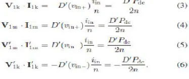
V1k · I1k denotes the phasor dot product, i.e., V1k ·
I1k = ( ˆV ˆI/2) cos(θv− θi). The notation V1k and I1k signifies thefundamental frequency ac rmsphasors for ˜v1k and˜i1k, respectively.That is, V1k = (ˆV /√2)∠θvand I1k = (ˆI/√2)∠θi. Pdcis the total dc power transfer between networks, as shown inFig. 4, where Pdc>0 corresponds to iin>0.Power balance constraints (3) through (6) reveal an average ac power equal to |D_Pdc/2n| must be exchanged between each outer arm and the adjacent inner arm. This is the same power exchange as given by Pac in Fig. 3, however, in Fig. 4 the polarity is explicitly shown. The direction of power exchangedepends on the polarities ofD_ (step-up/step-down) and Pdc(dc power transfer direction). For example, Fig. 4 shows the outer arms must deliver average ac power to the inner arms for: 1)D_ >0, Pdc>0; and 2) D_ <0, Pdc<0. A set of constraints similar to (3) through (6) can be formulated for the remaining string(s) in Figs. 1 and 2. To ensure a net ac voltage is not impressed across the input or output dc terminals, requirements are imposed on the synthesized arms voltages
In general, symmetry constraints similar to (7) and (8) are imposed on each string. Taking into consideration the phase shift between modulating waveforms of each string, interleaving of strings as shown in Figs. 1 and 2 offers natural cancellation of ac output inductor currents independent of D. For example,˜i1 and˜i2 in Fig. 2 always sum to zero as they are phase shiftedby 180◦. As a result, Cfideally carries zero current and pole voltages vout+ and vout−are free of fundamental frequency ac stimuli. However, in practice Cfwill carry a small amount of high-frequency current due to switching of the SMs. Based on the preceding discussion, the DC-MMCs in Figs. 1 and 2 internally circulate a total average ac power of |D_Pdc|. Note interconnecting two HVDC networks of similar voltage levels requires only a small amount of ac power to be circulated. In contrast, for D = 0.5 the DC-MMC must internally circulate 50% of the total dc power transfer in terms of ac power.
B. Steady-State Power Balance of SM Capacitors
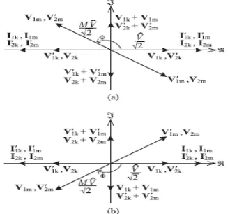
multistring implementation of the DC-MMC. In particular, ac phasor diagrams used in converter analysis are simplified, ensuring key aspects of the single-stage dc/dc conversion process are clearly illustrated.Fig. 5 gives two example ac phasor diagrams that illustrate the fundamental power transfer mechanism employed to achieve steady-state power balance of eachSMcapacitor in Fig. 2, for all possible operating modes of the DC-MMC. The peak magnitude of the ac arms voltages is denoted by ˆ V .Φ is the phase shiftbetween ac voltages of each outer arm and the adjacent inner arm, with positive values of Φ defined for the inner arm voltage leading the outer arm voltage. For example, positive values of Φ for string #1 correspond to V1m leading V1k and V_1m leading V_1k. Note the modulating waveforms of each string are displaced by 180◦.It is easy to visualize via phasor dot products that each pairof inner and outer arms in Fig. 5 exchange equal average ac power as dictated by (3) through (6). However, adopting such a strategy constrains each pair of arms to equally share the reactive power requirements of the composite load formed by Lr and La . This implies each arm operates at an equal ac power factor (in Fig. 5, the example case of power factor equal to 0.707
Fig: 5. Fundamental frequency ac rmsphasor diagrams that illustrate the power transfer mechanism used to achieve power balance of SM capacitors in Fig. 2, with ac output filter currents neglected, valid for: (a) D <1, iin>0andD>1, iin<0; (b)D <1, iin<0 andD>1, iin>0.
is shown where Φ = ±90◦). A preferred strategy is to impose unity power factor on the outer arms while realizing near unity power factor operation for the inner arms as shown in Fig. 6. Here, M is the ratio of inner arm to outer arm ac voltage magnitudes, e.g., M = |V1m/V1k|. For a fixed ˆ V , this modulation scheme minimizes the circulating ac currents needed for the dc/dc conversion process when operating with larger values of D (further details in Section V). Moreover, it significantly reduces the circuit reactance required to establish the circulating ac currents.Based on Figs. 4 and 6, the average power
exchanged between each outer arm and the adjacent inner arm is
Where
Positive values of Pk/m denote average ac power delivered from each outer arm to the adjacent inner arm of the same string. In general, Pk/m is adjusted by changing any combination ofM, ˆ V or Φ. Converters designed with smaller Xroffer reduced circuit var requirements and result in values of |Φ| approaching 180◦. Equation (10) reveals the DC-MMC can in fact be operated with Lrequal to zero. That is, the midpoints of each string in
Fig. 6. Fundamental frequency ac rmsphasor diagrams depicting modulation strategy to ensure power balance of SM capacitors in Fig. 2 while imposing unity power factor on outer arms and near unity power factor operation on inner arms, with ac output filter currents neglected, valid for: (a)D<1, iin>0 and D >1, iin<0; (b)D <1, iin<0 andD>1, iin>0.
Power balance criteria (11) is a primary design equation quantifying the amount of average ac power that must be exchanged between arms in steady state, as a function of the voltage conversion ratio and dc power transfer between HVDC networks. Furthermore, (11) provides additional insight into DC-MMC operation as it relates ac and dc power transfer mechanisms. Substituting n = 2 reveals each pair of arms in Fig. 2 exchange |D_Pdc/4| of average ac power via circulating ac currents.
IV. BIDIRECTIONAL DC FAULT BLOCKING CAPABILITY
In addition to enabling step-up operation and the interconnection of HVDC networks with similar voltage levels, the FB/SMs in Figs. 1 and 2 can provide bidirectional fault blocking. That is, the DC-MMC can interrupt fault currents initiated by dc faults in either the input or output side networks similar to a dc circuit breaker. This is accomplished by controlling the FB/SMs in Figs. 1 and 2 to impose the appropriate polarity of voltage during fault events, thereby blocking the flow of fault currents. This strategy is similar to the recognized fault blocking scheme for the dc/ac MMC. The inner arms of the DC-MMC need only to employ HB/SMs as no benefit is realized with bipolar voltage injection. In general, to ensure bidirectional fault blocking the 2k outer arm SMs within each string must collectively provide enough blocking voltage to counteract the larger of vin+ + vin−and vout+ + vout−.
V. OPEN LOOP VOLTAGE CONTROL
Open loop control techniques for balancing of SM capacitor voltages within the dc/ac MMC have been discussed in several papers. One of the simplest forms of open loop control, direct modulation adopts fixed sinusoidal modulating signals for the MMC arms. Balancing of SM capacitor voltages is achieved by a sort and selection algorithm that arranges capacitors based on their voltage measurements, and inserts the appropriate one(s) at each switching instant based on arm current measurements. This basic modulation scheme, although allowing second harmonic currents to circulate between phase legs, is sufficient to maintain stable power transfer between dc and ac side terminals of the dc/ac MMC. However, such a modulation approach alone is inherently incapable of maintaining voltage balance of SM capacitors for the DC-MMC. This is because the DC-MMC employs a fundamentally different power transfer mechanism: the direct exchange of average ac power between arms (see Fig. 4). Any slight imbalance in this power exchange will cause the SM capacitor voltages to
diverge. Consequently, some form of regulation is required.
A. Circulating AC Current Control
Fig. 7 shows the proposed circulating ac current controlscheme that enables open loop voltage control of the two-string DC-MMC. The control structure is partitioned into four blocks for each string; inner and outer arm logic for the positive and negative poles. To maintain power balance of the SM capacitors, closed loop control of the circulating ac currents is adopted
Volume 4, Issue 4 SEP 2016
Fig: 7. Circulating ac current control for each string (i.e., x ∈ {1, 2}) enabling open loop voltage control of the two-string DC MMC.
currents. Similar to the dc/ac MMC, a sort algorithm orders the SM capacitors in each arm from lowest to highest voltages. Using the reference voltage modulating signals for each arm,e.g., [v∗1k, v∗1m, v_∗1m, v_∗1k] for string #1, the SPWM blocks generate gating signals by selecting the appropriate SM capacitor(s) (via sort algorithm) to insert at each switching instant based on arm current direction and arm voltage polarity. The nominal voltage of each SM capacitor is denoted by V ncap. In Fig. 7, the dc components of the modulating signals are fixed for all arms based on the desired converter voltage conversion
ratioD. This is sufficient for open loop voltage control
of the DC-MMC. In practice, additional control loop(s) would be needed to regulate the dc output currents from each string to ensure proper current/power sharing between strings.
FUZZY LOGIC CONTROLLER
In FLC, basic control action is determined by a set of linguistic rules. These rules are determined by the system. Since the numerical variables are converted into linguistic variables, mathematical modeling of the system is not required in FC. The FLC comprises of three parts: fuzzification, interference engine and defuzzification. The FC is characterized as; i. seven fuzzy sets for each input and output. ii. Triangular membership functions for simplicity. iii. Fuzzification using continuous universe of discourse. iv. Implication using Mamdani‟s „min‟ operator. v. Defuzzification using the „height‟ method
Fuzzy logic controller
Fuzzification:
Membership function values are assigned to the linguistic variables, using seven fuzzy subsets: NB (Negative Big), NM (Negative Medium), NS (Negative Small), ZE (Zero), PS (Positive Small), PM 5 (Positive Medium), and PB (Positive Big). The partition of fuzzy subsets and the shape of membership CE(k) E(k) function adapt the shape up to appropriate system. The value of input error and change in error are normalized by an input scaling factor
Membership Functions
Interference Method:
Several composition methods such as Max–Min and Max-Dot have been proposed in the literature. In this paper Min method is used. The output membership function of each rule is given by the minimum operator and maximum operator. Table 1 shows rule base of the FLC.
Defuzzification:
As a plant usually requires a non-fuzzy value of control, a defuzzification stage is needed. To compute the output of the FLC, „height‟ method is used and the FLC output modifies the control output. In recent years, the number and variety of applications of fuzzy logic have increased significantly. The applications range from consumer products such as cameras, camcorders, washing machines, and microwave ovens to industrial process control, medical instrumentation, decision-support systems, and portfolio selection. To understand why use of fuzzy logic has grown, you must first understand what is meant by fuzzy logic. Fuzzy logic has two different meanings. In a narrow sense, fuzzy logic is a logical system, which is an extension of multivalve logic. However, in a wider sense fuzzy logic (FL) is almost synonymous with the theory of fuzzy sets, a theory which relates to classes of objects with unsharp boundaries in which membership is a matter of degree. In this perspective, fuzzy logic in its narrow sense is a branch of fl. Even in its more narrow definition, fuzzy logic differs both in concept and substance from traditional multivalve logical systems.
In fuzzy Logic Toolbox software, fuzzy logic should be interpreted as FL, that is, fuzzy logic in its wide sense. The basic ideas underlying FL are explained very clearly and insightfully in Foundations of Fuzzy Logic. What might be added is that the basic concept underlying FL is that of a linguistic variable, that is, a variable whose values are words rather than numbers. In effect, much of FL may be viewed as a methodology for computing with words rather than numbers. Although words are inherently less precise than numbers, their use is closer to human intuition. Furthermore, computing with words exploits the tolerance for imprecision and thereby lowers the cost of solution.
SIMULATION RESULTS
Two operating scenarios for the two-string DC-MMC are simulated in PLECS to validate the open-loop voltage control strategy proposed in Fig. 7. The scenarios include: 1) D = 0.5 (step-down); and 2)D= 1.1 (step-up). For each scenario, the dc power transfer between networks Pdcis 14MW. A full
switched model of Fig. 2 is implemented with four SMs per arm, i.e., k =m = 4; ideal switches are utilized. In both cases iin>0 (and thus Pdc>0) such that Fig. 6(a) and (b) is utilized. To ensure power balance of SM capacitors, the two-string DC-MMC must exchangeD_Pdc/4 of average ac power between inner and outer arms (see Fig. 4). The fundamental modulating frequency of the
arms voltages is selected as 50 Hz. The APOD SPWM scheme is adopted, although alternative modulation schemes can be used. In thesubsequent discussions, the string model in Fig. 4 and phasorsdiagrams.
1) Step-Down Operation: Simulation results for D =
0.5 with dc power transfer from input to output are given in Fig. 8.
Fig: 8. Simulation results for two-stringDC-MMCwithD =
0.5 and iin>0;ˆV = 3.5 kVpk, V ncap = 2.2 kV, Ls = 0 mH,
Cs = 0 μF.
is achieved with an ac voltage for the outer arms of ˆ V = 3.5 kVpkand circulating ac currents of 1.0 kApk.Fig. 8 shows the ac currents in the arms circulate in a symmetric fashion about the converter midpoint as dictated by Fig. 4, e.g.,˜i1k =˜i1m = −˜i_1m = −˜i_1k. All of the arms have the same dc current magnitude of 0.398 kA (iin/2) due to the fact D_ = D = 0.5. However, outer arms currents i1k, i_1k, i2k, i_2k have a positive average value (+0.398 kA) while inner arms currents i1m, i_1m, i2m, i_2m have a negative average value (–0.398 kA). The opposing polarity of dc arms currents aligns with Fig. 4 and is a result of the DC-MMC operating in stepdown mode. As demonstrated by i1, i2 and i_1, i_2 waveforms, Lf imposes a large ac impedance and confines the circulating ac currents within the DC-MMC structure. This validates the priorassumption of negligible ac output inductor currents.In Fig. 8, the ac components of the arms modulating signals(i.e., scaled versions of ac arms voltages) and ac components ofthe arms currents align with the phasor diagram in Fig. 6(a). Averageac power is delivered from each outer arm to the adjacentinner arm, with outer arms operating at unity power factor andinner arms supplying the necessary vars. For example, ˜v1k and˜i1k in Fig. 8 are phase-shifted 180◦ (outer arm delivering averageac power at unity power factor) while ˜v1m slightly lags˜i1m(inner arm receiving average ac power near unity power factorand supplying vars). To supply reactive power the inner armshave a slight larger ac voltage magnitude relative to the outerarms, as illustrated in Fig. 6(a).SMcapacitor voltage waveformsplotted for string #1 verify charge balance is achieved via the described power transfers. Similar waveforms exist for string#2. The balancing of SM capacitor voltages as shown validatesthe adopted closed loop ac current control strategy. As can be seen in Fig. 8, iinand ioutcontain a small secondharmonic (i.e., 100 Hz) ripple component. This open-loopoperating characteristic of the DC-MMC is not captured inSection III as the analysis is restricted to fundamental frequencyoperation. The second harmonic current ripple can be mitigatedby increasing the energy storage capacity of the SMs (i.e., increasingCsm). Furthermore, it is likely that supplemental armvoltage control can be incorporated to suppress the generationof second harmonic voltages, similar to the dc/ac MMC.For this case study, the SM capacitors are sized to achieve acceptable100-Hz current ripple as well as tolerable capacitorvoltage ripple.
2) Step-Up Operation:
Simulation results for D = 1.1 are provided in Fig. 9. The input voltage of ±8.8 kV is now stepped up to ±9.68 kV. This scenario is chosen to demonstrate the DCMMC’s ability to interconnect dc networks of similar voltages by exploiting FB/SMs
Fig: 9. Simulation results for two-stringDC-MMCwith
D =1.1 and iin>0;ˆV = 1.2 kVpk, V ncap = 2.9 kV,
Ls =0.5mH, Cs = 40 μF.
elementsLs = 0.5 mH and Cs = 40μF are utilized for the stepupscenario to reduce switching ripple for iin. For the step-downscenario, an input filter is not required. This is affirmed by very low switching ripple content in Fig. 8. Note, in both Figs. 8 and9 the DC-MMC can provide bidirectional fault blocking as theouter arms have sufficient voltage to withstand the larger of theinput or output dc terminal voltages.
VII. CONCLUSION
A new modular multilevel dc/dc converter, termed the DCMMC,is presented for the interconnection of bipolar HVDCnetworks. The DC-MMC features a new class of bidirectionalsingle-stage dc/dc converters utilizing interleaved strings of cascadedSMs. Power balance for each SM capacitor is achievedvia circulating ac currents, which are established by reactiveelements linking each string.,The two-string and three-string architectures for the DCMMCare introduced, where the latter shows similarity to thethree-phase dc/ac MMC structure. In general, an arbitrary numberof strings can be interleaved. By employing a unique arrangementof HB/SMs and FB/SMs for each string, the DCMMCcan provide both step-up and step-down operations and interconnect HVDC networks of
similar voltage levels. Moreover, the utilization of a sufficient number of cascaded FB/SMs in the outer arms enables bidirectional fault blocking capability similar to a dc circuit breaker. A simplified model of the converter strings is presented and the ideal dc/dc conversion process is analyzed in detail. An open loop voltage control scheme is proposed for the single string and two-string architectures that adopts closed-loop ac current control to maintain power balance of the SM capacitors. The proposed scheme has the benefits of minimizing the circulating ac currents needed for the dc/dc conversion process while significantly reducing the installed circuit reactance.
REFERENCES
[1] R. Majumder, C. Bartzsch, P. Kohnstam, E. Fullerton, A. Finn, and W. Galli, “Magic bus: High-voltage DC on the new power transmission highway,” IEEE Power EnergyMag., vol. 10, no. 6, pp. 39–49, Nov. 2012.
[2] W. Chen, A.Q. Huang, C. Li, G.Wang, andW. Gu, “Analysis and comparison of medium voltage high power DC/DC converters for offshore wind energy systems,” IEEE Trans. Power Electron., vol. 28, no. 4, pp. 2014– 2023, Apr. 2013.
[3] F. Deng and Z. Chen, “Control of improved full-bridge three-level DC/DC converter for wind turbines in a DC grid,” IEEE Trans. Power Electron., vol. 28, no. 1, pp. 314–324, Jan. 2013.
[4] J. W. Bialek, “European offshore power grid demonstration projects,” in Proc. IEEE Power Energy Soc. General Meet., Jul. 2012, pp. 1–6. [5] D. Das, J. Pan, and S. Bala, “HVDC light for large offshore wind farm integration,” in IEEE Power Electron. Mach.Wind Appl., Jul. 2012, pp. 1 7 [6] J. Robinson, D. Jovcic, and G. Joos, “Analysis and design of an offshore wind farm using a MV DC grid,” IEEE Trans. Power Del., vol. 25, no. 4, pp. 2164–2173, Oct. 2010.
[7] C. Meyer, M. Hoing, A. Peterson, and R. W. De Doncker, “Control and design of DC grids for offshore wind farms,” IEEE Trans. Ind. Appl., vol. 43, no. 6, pp. 1475–1482, Nov./Dec. 2007.
[8] S. S. Gjerde and T. M. Undeland, “Control of direct driven offshore wind turbines in a DC-collection grid within the wind farms,” in IEEE TrondheimPowerTech, Jun. 2011, pp. 1–7.
[9] A. Orths, A. Hiorns, R. Van Houtert, L. Fisher, and C. Fourment, “The European north seas countries’ offshore grid initiative—The way forward,” in IEEE Power Energy Soc. General Meet., Jul. 2012, pp. 1–8.
BIOGRAPHIES
Mr. POONAMALLI BALAJI was born in India. He is pursuing M.Tech degree in Power electronics in EEE Department in Visvodaya Institute Of Technology and Science , Kavali , SPSR Nellore District , Andhra Pradesh State , India . Email id: [email protected]
Student Details:
Guide Details:

![[μ N,N′ Bis(2 pyridylmethylene)ethane 1,2 diamine]bis{aqua[N,N′ bis(2 pyridylmethylene)ethane 1,2 diamine]manganese(II)} tetrakis(perchlorate)](data:image/gif;base64,R0lGODlhAQABAIAAAP///wAAACH5BAEAAAAALAAAAAABAAEAAAICRAEAOw==)