Evolution of Microgrids with Converter-Interfaced Generations: Challenges
and Opportunities
Md Alamgir Hossain∗1,2, Hemanshu Roy Pota1, Md Jahangir Hossain3, and Frede Blaabjerg4 1School of Engineering & Information Technology, The University of New South Wales, Canberra, ACT-2610, Australia
2Department of Electrical & Electronic Engineering, Dhaka University of Engineering and Technology, Gazipur, Bangladesh 3Department of Engineering, Macquarie University, Sydney, NSW-2109, Australia
4Department of Energy Technology, Aalborg University, Denmark
Abstract
Although microgrids facilitate the increased penetration of distributed generations (DGs) and improve the
security of power supplies, they have some issues that need to be better understood and addressed before
real-ising the full potential of microgrids. This paper presents a comprehensive list of challenges and opportunities
supported by a literature review on the evolution of converter-based microgrids. The discussion in this paper
presented with a view to establishing microgrids as distinct from the existing distribution systems. This is
accomplished by, firstly, describing the challenges and benefits of using DG units in a distribution network
and then those of microgrid ones. Also, the definitions, classifications and characteristics of microgrids are
summarised to provide a sound basis for novice researchers to undertake ongoing research on microgrids.
Keywords: Converter-based microgrids, distribution networks, renewable energy sources, definitions of
microgrids and distributed generation units.
Abbreviations
The following abbreviations are used in this manuscript:
DGs Distributed generations
RESs Renewable energy sources
PECs Power electronic converters
DFIG Double-fed induction generator
PV Photovoltaic
PCC Point of common-coupling
MGCC Microgrid central controller
CO2 Carbon dioxide
CHP Combined heat and power
HVDC High-voltage direct current
CSCs Current-source converters
VSCs Voltage-source converters
UPS Uninterruptible power supply 5
∗Corresponding author
Emailaddress:[email protected][email protected](MdAlamgirHossain∗1,2)
EVs Electric vehicles
FACTS Flexible alternating current transmission systems
DSTATCOM Distribution static synchronous compensator
UPQC Unified power quality conditioner
THD Total harmonic distortion
MSAT Multiphase staggering auto-configured transformer
SVCs Static var compensators
CPDs Custom power devices
NPC Neutral point clamped
STATCOM Static synchronous compensator
APLC Active power line conditioner
PSO Particle swarm optimisation
MFD Morphological fault detector
HIL Hardware-in-loop
STS Static transfer switch
CERTS Consortium for electric reliability technology solutions
NEDO New energy and industrial technology development organisation
INESC TEC Institute for systems and computer engineering, technology and science
EU European union
LV Low-voltage
MV Medium-voltage
HV High-voltage
EMS Energy management system
IDE4L Ideal grid for all
PHEVs Plug-in hybrid EVs
MGCC Microgrid central controller
SCADA Supervisory control and data acquisition
MAS Multi-agent system
KnEA Knee-point-driven evolutionary algorithm
FCL Fault current limiter
SRCU Supervisory remote control unit
NDZ Non-detection zones
ICT Information and communication technology
PLCC Power line carrier communication
NN Neural network
DNO Distribution network operators
GA Genetic algorithm
IWD Intelligent water drops
0 20 40 60 80 100 120 140 160 180
2008 2009 2010 2011 2012 2013 2014 2015 2016 2017
B il li n o n s o f Do ll ar s Years Wind Solar (a) 0 100 200 300 400 500 600
1995 1997 1999 2001 2003 2005 2007 2009 2011 2013 2015 2017 Wind Solar P o w er g en er atio n (GW ) Years (b)
Figure 1: Wind and solar power: (a) global investment and (b) worldwide power generation.
ARMA Autoregressive moving average models
NWP Numerical weather prediction
MLIP Mixed linear integer problem
ADP Adaptive dynamic programming
I-DEMS Intelligent dynamic energy management system
EDRP Emergency demand response program
TOU Time of use
RTP Real-time pricing
CPP Critical-peak pricing
1. Introduction
Currently, there is a shift in power generation from conventional energy sources to renewable ones for a
number of reasons. These include mitigating the effects of climate change and the gradual depletion of energy 10
sources (coal, gas and oil), dealing with the steadily increasing consumption of energy, satisfying the need for
local economic and social development, reducing power losses over long transmission lines and decreasing the
amount of investment required to construct new power transmission lines [1, 2]. Figures 1a and 1b depict
investments in solar and wind power, and their integration in generating power around the world [3]. Figure 1a
shows that, until 2009, greater priority was given to investing in wind than solar power generation. However, 15
since then, the trend has been reversed. These renewable energy sources (RESs) connecting to a distribution
network with the help of power electronic converters (PECs) can provide alternative power sources to traditional
ones. The high penetration of RESs in an existing distribution network may lead to concerns regarding the
reliability and stability of the system due to the stochastic nature of their power generation and load demand [4].
These difficulties for the grid utility to control distributed resources can be minimised by logically partitioning a 20
distribution network into zones with individual identities. When these smaller networks are capable of regulating
their own regions without the help of the grid utility, which is possible because of their own control units there,
they are identified as microgrids. Then, they can form clusters from the grid perspective and the management
of the entire distribution network as microgrids overcomes the challenges, limiting the integration of RESs
into distribution systems. Therefore, a better understanding of how these sources interact with distribution 25
There is a number of literature review on microgrids from different perspectives, including components,
controls, assessments and policies. In [5], different multilevel converters with newer topologies for the application
of RESs, namely wind and solar, are presented. Some recently developed control strategies (inner-loop and
primary) for operating them in an effective and efficient way, together with their relative advantages and 30
disadvantages, are documented in [4]. Adaptive and intelligent control methods for achieving microgrid stability
and reliability are discussed in [6]. The stability of a microgrid based on the features of its components is
assessed in [7]. In [8], a multi-agent system (MAS) for microgrid control and optimisation is reported. The
basic structures of multi-microgrids with key technologies from the perspectives of voltage-grade classification
as well as phase-sequence and ac/dc constitutional forms are discussed in [9]. In [10], microgrids are classified 35
in terms of a hierarchical organisational scheme. The influence of government policy on the implementation
of microgrids from the economic perspectives is presented in [11]. In [12], the parameters of typical ac and
dc microgrids are described, and some of the issues involved in their implementation and development are
presented for the selection of a suitable configuration of a microgrid.
While there are many research or review papers on the control, operation and management of microgrids [5, 40
6, 8, 7, 10, 9, 11, 13, 4, 14], there is a gap in terms of identifying the definition and characteristics of
converter-based microgrids and all their possible related challenges and opportunities to distinguish them from distribution
networks. To bridge this gap, this paper offers the following contributions. As well as an updated review of
the different issues concerning microgrids, the definitions and characteristics of state-of-the-art converter-based
microgrids revised according to their specific roles are presented. The most distinguishing feature of this paper 45
is a comprehensive analysis that differentiates a microgrid from a distribution network considering all possible
issues to avoid the confusion that often arises regarding microgrid terms. Also, the very early developments of
power systems and then the most advanced ones are discussed, with future possible research trends highlighted
to assist novice researchers.
The rest of this paper is organised as follows. Section 2 briefly describes the development from traditional 50
to modern power systems. In Section 3, the advantages and disadvantages of using DG units in a distribution
network are discussed. Section 4 presents the evolution, classifications, characteristics and definitions of
mi-crogrids, and also discusses their future challenges and opportunities. In Section 5, future trends in microgrids
for upcoming researchers to advance the field is stated. Section 6 draws the conclusion.
2. Background of modern power system
55
In the early stages of electricity generation, generators were placed near the premises that consumed the
power produced. With the increasing demand for electricity, the disadvantages of this approach became
ap-parent, and it led to the evolution of centralised power systems. A centralised power generation station were
installed to minimise costs and improve the security of supply [15]. Prior to the 1990s, attempts to build
increasingly larger power stations for financial benefits involved these stations being located either near fuel 60
sources or in remote places for safety reasons. This indicates they were further away from the point of power
consumption both electrically and geographically. Generally, in a large power station, a fossil fuel (coal, gas
or oil) is burnt in a furnace to produce high-pressure steam which strikes a turbine’s blades and rotates them,
Unidirectional power flow
Bidirectional power flow due to DG units
PCC
DGn
L
DG2Microgrid
Generating
s
tations
Distribution
n
etwork
G1
G2
Gn
DG1
MGCC
Transmission
n
etwork
Loads
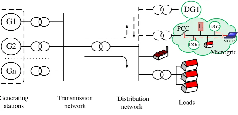
Figure 2: Evolution from traditional to modern power systems.
voltage of the generated power is stepped up by a transformer to a high-voltage (HV) to send the electricity 65
long distances through transmission networks to substations where the voltage is stepped down to a medium
and/or low-voltage (MV and LV, respectively) to reach end-users through distribution networks [16], as shown
in Figure 2. Therefore, the generated electricity flows through transmission lines from large generation points
to distribution points, i.e., it is a unidirectional (radial) power flow.
Since the 1990s, the construction of larger power systems has been discouraged for several reasons, including 70
their increasing CO2 emissions, being energy deficient, lacking security of supply and incurring transportation
losses [17, 18]. Now, most governments provide financial incentives for the exploitation of renewable
energy-based power generation, the generators for which are, by nature, smaller than conventional ones. Therefore,
small-scale power generators driven by RESs are increasingly being directly connected to distribution networks
whereby consumers have direct access to electricity generation. These small-scale units are defined as distributed 75
generation (DG) units.
Incorporating DG units in a distribution network represents a fundamental change from a traditional power
system as the resultant power flow is bidirectional as shown in Figure 2. Although these units are based
mainly on RESs, such as solar and wind generators, they can rely on other sources, such as micro-turbines,
gas turbines, fuel cells, biogas and combined heat and power (CHP) units [19, 20, 21]. DG units driven by 80
RESs have demonstrated significantly increased electricity generation over the last two decades [22], as shown
in Figure 1b. The integration of these sources in a distribution network demonstrates both merits and demerits
for the existing power system.
3. Benefits and challenges of using DG units in distribution networks
3.1. Benefits of using DG units 85
DG units, which are small generators, offer numerous advantages compared with conventional large power
plants. Some of their key features described in the following subsections emphasise the importance of current
Reliable electricity supply: As explained in Section 2, in a traditional power system, a generator produces
bulk power (500 MW) in one place and transmits it to other places (end-users, i.e., consumers) to service a large 90
community. On the other hand, a DG unit, the rating of which is typically low (less than 5 MW), produces
electricity and services for a local small community. In the case of the failure of a 500 MW generator, the
system needs to either produce an extra 500 MW of power from reserve units or shed a 500 MW load to save
the system from a cascading generator shutdown. In contrast, power failures in DG units have less impact on
the system and are often manageable because of the small-scale power generation [24]. 95
Reduced transmission losses: Electrical power flows from a power station to consumer premises through
transmission lines which have inherent resistance and reactance that cause them to lose power. If 142 A current
flows through a line as shown in Table 1, a 0.642 Ω km−1 resistance in a line leads to a 12.95 kW km−1 loss.
Installing DG units near consumer premises can minimise I2R losses which improves network efficiency [25].
Reduction in feeder capacity: The gradually increasing demand for power as a result of the desire to 100
maintain high living standards for an increasing population necessitates changing the components of a power
system used in transmission lines. The penetration of DG units in a distribution network reduces stresses on
both transmission line equipment and distribution lines at times of peak demand [26]; for example, as patterns
of daily office loads are more or less similar to the generation of solar power, the need to import power from the
grid is avoided which places less stress on transmission lines. Therefore, using DG units, which encourage more 105
load participation in a distribution network, can be more economical than upgrading a network’s components.
Integration of RESs: The majority of DG technologies used in a network are based on RESs which have
abundant input power and do not emit CO2, i.e., they are environmentally friendly. Installing DG units around
load centres provides an enhanced voltage profile and better power quality [27]. Research on DG technology is
gradually reducing their production costs and increasing the power conversion efficiency of DG units, thereby 110
leading to their being attractive choices for future power generation.
3.2. Challenges of implementing DG units
Conventional electricity structures have accommodated the installation of DG technologies in a distribution
network although this can affect various quantities of a power system, such as its voltage profile and power flow.
Important concerns regarding power quality, changes in a network’s voltage and fault levels, system stability, 115
modelling of networks’ components and low inertia for the operation of DG units in a distribution network are
briefly discussed in the following subsections.
Power quality: The power quality of a distribution network can be altered by the penetration of DG units
which, if operated based on RESs, may lead to problems such as voltage fluctuations, harmonic distortions,
frequency deviations and voltage flickers [29]. This is because the variable outputs of DG units cause reverse 120
power flows, and the use of many PECs produces harmonics in the injected power. Also, the connection and
disconnection of a DG unit to/from a network may cause transient currents which lead to a high-magnitude
voltage [30]. Voltage flicker can be minimised by imposing constraints on how and when DG units change
their outputs while a great deal of attention has been paid to increasing the power quality of a network during
voltage disturbances [31, 32]. The power quality of a distribution network can be improved in several ways, 125
including by applying better control strategies for the inner-current control of converters, designing filters for
Loads
Z=R+jX
LV
V2
Z1 V3
Z2 V4
Z3 V5
Loads Loads
Loads MV
V1
DG DG DG
1
V
o
lt
ag
e
(p
.u
.)
Desired voltage profile
Voltage without DG units
a b c d
Distance (km) Voltage with DG units
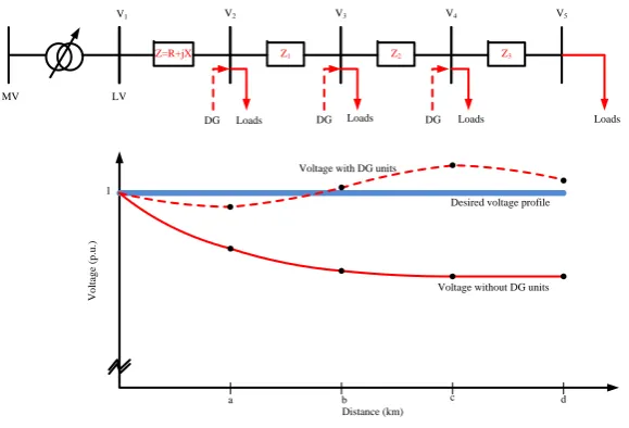
Figure 3: Impact of DG integration on voltage profile of a radial distribution network.
(FACTS) devices in networks [33, 34].
Power quality is generally enhanced by the installation of devices at customers’ supply points, such as a
series compensator (dynamic voltage restorer (DVR)), a shunt compensator (distribution static synchronous 130
compensator (DSTATCOM)), and hybrid series and shunt compensators (unified power quality conditioner
(UPQC)). A series compensator is employed for voltage-related issues and a shunt compensator for minimising
current-related ones, such as the effects of an imbalance, harmonics and the power factor. A dual-tree complex
wavelet transform-based control algorithm for a DSTATCOM to enhance power quality in a distribution network
is presented in [34]. The total harmonic distortion (THD) in this method is less than 5 % with the application 135
of various load conditions under the unity power factor. A 20-pulse multiphase staggering autoconfigured
transformer (MSAT), a combination of delta and zig-zag transformers, to improve power quality in MV and
high power applications is discussed in [35].
Change in network voltage: The main function of a DG unit is to supply power within acceptable
voltage ranges to customers. Although the standards for voltage profiles vary from country to country, their 140
operating principles are the same as that of radial feeders which are generally arranged in such a way that the
power flow is unidirectional, i.e., the power flows from the generator to the load. As a result, a poor voltage
profile as shown in Figure 3 is observed at the most remote node because of the voltage drop in impedance
along the radial lines. This problem can be minimised by inserting DG units directly into a network; however,
this causes a bidirectional power flow along the lines that require complex protection schemes for the network 145
[36]. If the impact of these variations in a radial network is significant, the locations, sizes and impedances of
these units must be appropriately measured [36].
The insertion of DG units can also vary the voltage profile due to the intermittency of the power generated
by RESs, especially on cloudy days or at times of low wind velocity, with a voltage collapse possibly leading to a
complete interruption of power [37]. To inject or absorb reactive power in a network, shunt capacitor banks and 150
static var compensators (SVCs) or FACTS devices need to be placed at optimal positions in the network [38].
Due to smaller size and faster response, a static synchronous compensator (STATCOM) is preferable to a SVC.
network. The real-time control of multiple custom power devices (CPDs) using STATCOM and active power
line conditioner (APLC) to improve voltage regulation in a distribution network are demonstrated in [37]. 155
In this strategy, two particle swarm optimisation (PSO) algorithms are implemented to obtain the optimal
sizing/siting and online control of multiple CPDs. In [40], the operational performance of a low-capacitance
cascaded H-bridge STATCOM is optimised to minimise switching losses.
Change in network fault level: A distribution network containing DG units is an active network in
which the power and extra current can flow in a reverse direction toward the fault side [41], with all types of 160
DG units assisting in increasing the fault level. Although synchronous and induction generators are capable of
supplying a fault current, inserting DG units can alter the fault level. Then, if all the associated protection
apparatuses are upgraded to maintain the equivalent fault level, costs will increase. Although involvement of
the fault level can be restricted by using an appropriate impedance, this technique augments power losses and
voltage changes [42]. 165
A robust and versatile algorithm for over-current protection considering changes in power generation and
demand is described in [43]. Faults are detected by studying abrupt changes in the current’s magnitude using a
multi-stage morphological fault detector (MFD). In [44], a hardware-in-loop (HIL) adaptive protection scheme
capable of addressing the DG effect by providing a flexible protection solution is introduced. As an adaptive
protection scheme depends on communication lines to adjust the relay setting, a communication failure becomes 170
a major threat to its security. Such a scheme that takes into account a super-capacitor’s energy to improve
resilience against communication failure is presented in [45]. In [46], a current limiting-approach and generalised
fault model for enhancing the fault ride-through capability of droop-controlled converter-interfaced DG units
are presented. A dc-link adjustable resistive type of fault current limiter for improving the fault ride-through
capability of a voltage-source converter (VSC) is presented in [47, 48]. 175
System stability: An interconnected power system, which is generally large, creates complex networks
in which different factors, including uncertainties in power generation and demand, can lead to instability. As
power generations from RESs highly reliant on weather conditions, several transient disturbances, which are
more complex and distributed than the existing ones, including a loss of power generation or system components
as well as faults, increase in a distribution network. 180
The stability of a network is generally concerned with its transient stability, ability of a system to return
back to its steady state when subjected to a large disturbance. In [49], the transient stability in Dutch 10
kV distribution network with micro-turbines, CHP plants, and wind generators is analysed. It is concluded
that DG units have transient stability issues in a network which should be taken into account during their
integration. A projective integration method considering a high penetration of DG units for the improvement 185
of the transient stability of a distribution network is described in [50]. In [51], the effect of a network’s transient
stability on its reliability during dynamic contingencies is assessed using a direct method. A robust transient
stability-constrained optimal power-flow model that takes into account uncertain variations in the model’s
parameters and dynamic loads is presented in [52]. A fuzzy-based damping controller that uses the frequency
to control the firing angle of a thyristor-controlled series capacitor to enhance the damping of electromechanical 190
oscillations in a distribution network is presented in [53]. The effects of a power system stabiliser and oscillation
modes of a distribution network are studied in [54].
Table 1: Typical line parameters.
Type R[Ω/km] X[Ω/km] IN (A) R/X
LV 0.642 0.083 142 7.73
MV 0.161 0.190 396 0.85
HV 0.060 0.191 580 0.31
Table 2: Comparison of different models [65].
Model Operating point Small-signal High frequency Non-symmetric network
Time-varying phasors Yes Yes No No
Dynamic phasors Yes Yes – –
abc No No Yes Yes
dq0 Yes Yes Yes No
by using time-varying phasor models (quasi-static models), often by means of network power flow equations, that
assume the frequency of signals is approximately constant [55]. Consequently, models are time-invariant, with 195
a well-defined operating point that facilitates the power system study. However, due to increasing penetration
of RESs into an existing distribution network, it becomes complex to observe the dynamic behaviours. This is
because of the introduction of power electronics, involved with harmonics in voltage and current signals that
may exhibit fast amplitude and phase variations [56]. As a result, the system may not be quasi-static in many
cases. To facilitate the analysis, several alternative models, including dynamic phasors, abcanddq0 reference 200
frame models, are developed [57]. In dynamic phasors, voltage and current signals are represented by Fourier
series expansions that evaluate harmonic components over a moving time window [58, 57]. It approximates
the system with nearly periodic quantities [59]. Different dynamic phasor based models of a power system are
demonstrated in [57]. The time-based model using the abcreference frame is often used in power systems for
the application of unbalanced networks, where frequency is not constant. Indq0-based models, the symmetric 205
electrical quantities are mapped into constant values. The assumption of quasi-static states is not required in
this model, and it can work at high frequencies [60]. A number of studies are presented based on dq0-based
models for analysing the network’s dynamics [61, 62, 63, 64]. A comparison among different models is shown
in Table 2.
Low inertia: In a conventional generator, the inertia as an energy – a form of kinetic energy stored in a 210
rotating mass of a synchronous generator – can support regulation of the network’s frequency and voltage up to
10 seconds during disturbances that lead to a generation-demand imbalance [66]. This inertia energy basically
minimises the impact induced from disturbances within the time frame, whereas other controllers take initiatives
after this step. However, the increasing penetration of converter-fed RESs that have non-existent or lower
inertia characteristics than synchronous generators reduces the inertia of an entire network, leading to voltage 215
or frequency fluctuations during an event [67, 68]. If appropriate control measures are not applied to minimise
these fluctuations within specified limits, the network may experience instability [69]. Several control strategies
that realise the role of inertia in a network have been developed from different perspectives; for example, in a
to enable the reserve power to act as an inertia energy during frequency or voltage fluctuations [70]. In the case 220
of a variable-speed wind generator, the rotor’s speed and blades’ pitch-angle controls can be used to reserve
the inertia power to respond to any change in the network [71]. Also, the kinetic energy of rotating blades can
be released using an appropriate control strategy for converters to respond in frequency deviations up to 2–6 s
[72]. Although these techniques, called de-loadings, can reserve some energy at the expense of constant energy
losses to emulate inertia behaviour, they may still cause reliability issues due to their reliance on the variable 225
factors of RESs.
To improve the reliability of a network, its low inertia can be enhanced by using batteries, capacitors and
flywheels at the dc busbars of its interfacing converters. A battery can be regarded as a reserve energy source
that responds to a network’s requirements, i.e., it can store or release energy according to the power demand
[73]. In [74], an ESS used as an inertia energy to regulate the frequency of a microgrid has the capability to 230
seamlessly transfer. A capacitor employed to decouple a converter’s input power from the boost converter’s
output can be used as an inertia of the converter to control the terminal voltage [1]. In order to apply the
well-established conventional control algorithms/theories to converter-interfaced generators, the concept of a
synchronverter, which mimics the behaviours of conventional synchronous ones over short periods of time for
the integration of RESs in a distribution network, is proposed in [75]. The amount of inertia depends on the 235
size of the virtual moment of the synchronverter’s inertia with capacitors typically used to mimic it. However,
to obtain a better performance that resists the intermittency of RESs, relatively large storage is preferable. An
improved synchronverter that limits its voltage and frequency to within acceptable ranges is presented in [76].
In [77], algorithms for a synchronverter are modified to include the virtual field current, virtual filter inductors,
(virtual) nominal active mechanical torque and virtual capacitors to enhance its performance and stability, and 240
bring the inverter’s characteristics much closer to those of synchronous machines. The hybrid use of a battery
and ultracapacitor, where the latter handles high-frequency and the former low-frequency power fluctuations
to implement a virtual synchronous generator, presented in [78] reduces power fluctuations. Researchers have
still opportunities to improve the inertia response by the application of novel control strategies and algorithms,
and the design of hybrid energy storage systems(ESSs). 245
4. Microgrids
4.1. Evolution of microgrid concept
To exploit the benefits of integrating DG units and overcome the issues related to the management of a
network’s components – DG units, loads and other equipment – from a grid utility perspective because of their
multi-dimensional activities, the concept of a microgrid has evolved [79]. The word ‘microgrid’ is comprised of 250
‘micro’ (an extremely small attribute from the perspective of a grid utility) and ‘grid’ (a network of electric
lines). Therefore, it is expected that microgrids will possess all the essential components of a power system in
a small range, except some unnecessary equipment, such as transmission lines and substations. The core idea
of a microgrid is to integrate a limited number of DG units to optimally control DG units without creating
a complex network. Its major components are a hierarchical control approach, a point of common coupling 255
(PCC), distributed controls using local information and a specific region that enable DG units to be integrated
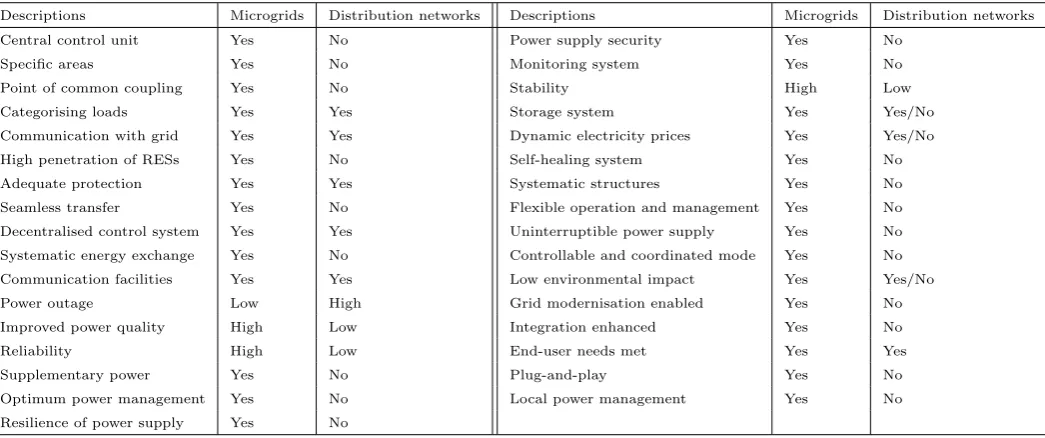
Table 3: Comparison of microgrids and modern distribution networks.
Descriptions Microgrids Distribution networks Descriptions Microgrids Distribution networks
Central control unit Yes No Power supply security Yes No
Specific areas Yes No Monitoring system Yes No
Point of common coupling Yes No Stability High Low
Categorising loads Yes Yes Storage system Yes Yes/No
Communication with grid Yes Yes Dynamic electricity prices Yes Yes/No
High penetration of RESs Yes No Self-healing system Yes No
Adequate protection Yes Yes Systematic structures Yes No
Seamless transfer Yes No Flexible operation and management Yes No
Decentralised control system Yes Yes Uninterruptible power supply Yes No
Systematic energy exchange Yes No Controllable and coordinated mode Yes No
Communication facilities Yes Yes Low environmental impact Yes Yes/No
Power outage Low High Grid modernisation enabled Yes No
Improved power quality High Low Integration enhanced Yes No
Reliability High Low End-user needs met Yes Yes
Supplementary power Yes No Plug-and-play Yes No
Optimum power management Yes No Local power management Yes No
Resilience of power supply Yes No
elements, protection equipment and a control scheme, all of which ensure the regulation of the power flow,
and voltage and frequency profiles within a defined region, it could be called a ‘distribution network control’
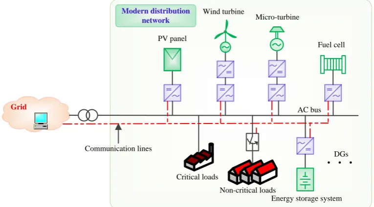
approach. However, as this description does not cover any specific region, it is not appropriate. Therefore, 260
the integration of DG units in a distribution network to export power cannot be considered a microgrid unless
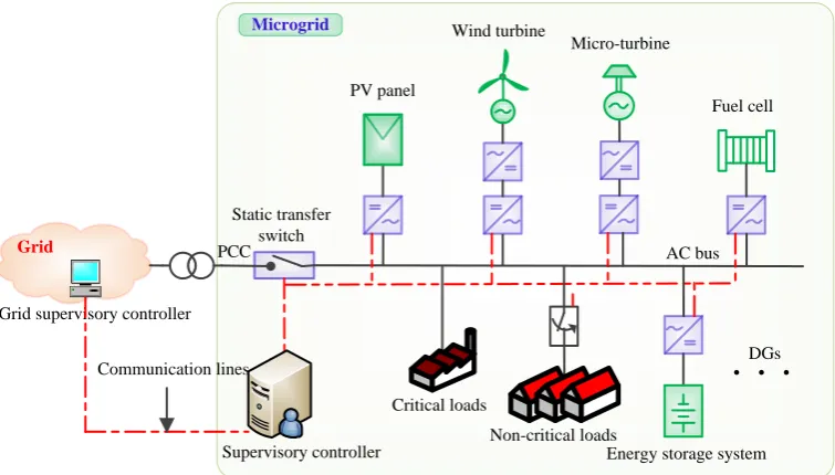
it has control over the network within a defined region. The microgrid concept and distribution network are
depicted in Figures 4 and 5, respectively, and their relative features presented in Table 3. One important point
is that encouraging the construction of microgrids is not contrary to using a conventional power system but,
rather, supplementary to a grid utility. 265
To obtain good services from a grid utility and DG units, microgrids are connected to the utility through a
static transfer switch (STS) at the PCC. This approach provides control of the participating equipment within
a defined region and enables the microgrid to be considered a single dispatchable unit from the grid perspective.
An individual owner of a microgrid can both supply power to a grid utility if the microgrid has excess power
and receive power if necessary. In a microgrid, generators deliver power at a certain voltage level during parallel 270
operation with the grid utility and provide sufficient power to, at least, critical loads. Ensuring a reliable power
supply for certain loads is the most important priority of a microgrid.
A microgrid can be disconnected during a period of deteriorating power quality or network contingencies
without affecting the local power supply. A degradation in power quality may occur during a violation of the
voltage limit of sensitive loads because, if the voltage quality hampers the equipment’s operation, only local DG 275
units can supply power to these loads. When, as an entity, a microgrid faces an unbalanced power supply, it
can intentionally island itself from the grid utility to retain the power quality required for sensitive loads. This
capability is effective for providing an uninterruptible power supply (UPS) to sensitive loads, not only when
there is a loss of the main power supply and/or a grid failure but also during a period of the power degradation.
A microgrid can be installed in any industrial area, official building, commercial centre or residential complex 280
to receive UPS services.
Table 4: Some global projects involving converter-based microgrids [80].
Name/Place Organisation/Institution DG Type Load
Aichi/Japan NEDO PV, Fuel Cell and Battery AC Industrial and Commercial
Albuquerque/US NEDO PV and Battery AC Residential/Commercial
Benchmark Low-voltage/Greece Microgrids Project PV, Wind, Fuel Cell, Flywheel and Battery AC Residential
Barcelona/Spain IREC PV, Wind, EV and Battery AC HVAC, Air Conditioners
Borrego Springs/US San Diego Gas & Electric PV, EV and Battery AC Residential and Industrial
California/US Santa Clara University PV and Wind AC University
Chicago/US Illinois Institute of Technology PV, Wind, EV and Battery AC –
Chico Mendes/Brazil Electrobas PV and Battery AC–DC –
Continuon Holiday Park/Netherlands More Microgrids Project PV and Battery AC Residential FIU Testbed/US Florida International University PV, Fuel Cell, Wind and Flywheel DC Residential and Motor
Fukuoka/Japan Smart Energy Laboratory Wind, PV and Battery DC –
Gazi University/Turkey Gazi University PV, Wind and Battery AC University
Hawaii Hydrogen Power Park/US Hawaii National Energy Institute PV, Wind and Fuel Cell DC Residential
Ilha da Ferradura/Brazil – PV and Battery AC –
Kyoto Eco Energy/Japan NEDO PV, Wind, Fuel Cell, Biogas and Battery AC Residential Laboratory scale MG Testbed/US New Jersey Government PV and Battery AC Residential and Motor
Los Alamos/US NEDO PV and Battery AC Residential
Lyon/France NEDO PV and EV AC –
Manzanita Hybrid Power Plant/US – Wind, PV and Battery AC –
Nanjing University/China Nanjing University PV, Wind and Battery AC Motor
RIT Microgrid/US Rochester Institute of Technology PV, Fuel Cell and Wind AC Residential and Motor Sino-Danish Project/China Aalborg University/Tsinghua University PV, Wind and Battery AC –
UTC/France University of Technology of Compigne (UTC) PV, Fuel Cell and Battery DC Motor NTUA/Greece National Technical University of Athens (NTUA) PV, Wind and Battery AC –
University of Nottingham/England University of Nottingham Wind and Battery DC Residential University of Miami Testbed/US University of Miami PV, Fuel Cell and Battery DC University Residential Woodstock/US National Renewable Energy Laboratory PV, Wind and Battery AC Shop and Office
Xcalak/Mexico – Wind and Battery DC Village
Table 5: Some research projects conducted on microgrids [81].
Project Title Budget Duration Promoter
CERTS 12.2 M USD from 1999 US
More Microgrids 8 Me 2006 to 2010 EU
IDE4L 8 Me 2013 to 2016 EU
Microgrids 4.5 Me 2003 to 2006 EU
Positas Microgrid 1.5 M USD from 2015 US
Grid supervisory controller
AC bus PV panel
Wind turbine
Static transfer switch
Grid PCC
Micro-turbine
Energy storage system Communication lines
Critical loads
Non-critical loads
Fuel cell
Microgrid
DGs
Supervisory controller
Figure 4: Concept of microgrid.
research projects shown in Tables 4 and 5. Many of these were developed for test beds around the world;
for example, the Consortium for Electric Reliability Technology Solutions (CERTS) in the United States of
America (USA); the New Energy and Industrial Technology Development Organization (NEDO) in Japan; 285
and The Institute for Systems and Computer Engineering, Technology and Science (INESC TEC) in Europe
[82, 80, 83]. Some were implemented by governments to provide secure, clean and efficient energy; for example,
in the USA, the Department of Energy spent 6.3 billion USD in the fiscal year 2012 on research, deployment
and development activities related to clean energy [81].
4.2. Characteristics of Microgrids 290
A microgrid has the following characteristics which distinguish it from DG units applied in a distribution
network [79, 84, 85, 86, 87, 88, 89, 90].
• It supervises the electrical components, such as powers, voltages and frequencies, by means of monitors.
• It has a PCC in a distribution network for connecting and disconnecting the grid utility.
• It is a subset of LV or MV distribution networks. 295
• It consists of generation units, a hierarchical control approach, power consumption places and ESSs.
• It facilitates an UPS to, at least, the highest priority loads during a grid failure or power quality
degrad-ation.
• It has two operating modes: 1) grid-connected; and 2) islanded or standalone (autonomous).
• It acts as a single controllable entity from a grid perspective. 300
• It generates the required reference voltage and frequency in an islanded operation.
AC bus PV panel
Wind turbine
Grid
Micro-turbine
Energy storage system Communication lines
Critical loads
Non-critical loads
Fuel cell
Modern distribution network
DGs
Figure 5: Modern distribution network.
• It has the necessary protection schemes.
• It controls the power supply during both grid-connected and islanded operations.
• It accumulates DG units, the ratings of which are less than 100 MW. 305
• It displays ‘plug and play’ features and ‘peer-to-peer’ functionality.
• It adjusts to abnormal situations (unintentional islanding or faults).
• It uses local information to control the power flow of DG units.
• It can possess ac and/or dc distribution networks.
• It may provide electrical energy and thermal energy (hot and/or cold) simultaneously. 310
4.3. Definitions of microgrids
According to [79], a microgrid is a subsystem consisting of generation and associated loads that uses local
control to facilitate its connection and disconnection to/from with the main grid in order to maintain a standard
service during disturbances without harming the integrity of the transmission grid.
According to [84], a microgrid is a possible future energy system paradigm formed by the interconnection 315
of small, modular generation units (micro-turbines, fuel cells, PV, etc.), storage devices (flywheels, energy
capacitors and batteries) and controllable loads in LV distribution systems. Such systems can be operated
interconnected to the power grid, or islanded, if disconnected from the grid.
In [85], a microgrid is defined as a cluster of distributed resource units and loads serviced by a distribution
system which can operate in a 1) grid-connected mode, 2) islanded (autonomous) mode, and 3) a ride-through 320
process between these two modes.
According to the U.S. Department of Energy Microgrid Exchange Group [86], a microgrid is a group of
AC bus Wind turbine
PCC
Micro-turbine
Storage system
Loads
Fuel cell
DC distribution MGCC
Grid operators
Grid
PV panel
M
Flywheel Compressed
air
DC bus
PHEVs Loads
AC distribution
Hybrid m icrogrid
Figure 6: Hybrid microgrid.
a single controllable entity with respect to the grid. It can connect to and disconnect from the grid to enable
it to operate in both grid-connected and islanded modes. 325
CIGR `E C6.22 Working Group in Microgrid Evolution Roadmap [87] describes microgrids as electricity
distribution systems containing loads and distributed energy resources (such as distributed generators, storage
devices and controllable loads) that can be operated in a controlled, coordinated way either when connected to
the main power network or islanded.
All the above definitions agree on the one point that a microgrid can be operated in either a grid-connected 330
or an islanded mode in a defined area to act as a controllable entity. However, these definitions do not mention
a control unit for facilitating the system’s features, such as seamless transfer, and working as a supplementary
power supply during an islanded operation. Also, they may not be appropriate for an islanded microgrid with
converter-interfaced generators that need a central control unit to obtain second-to-second power balancing and
optimal use of these sources. 335
Based on the above definitions and characteristics, in this paper, a microgrid is defined as follows. A
mi-crogrid (consisting of small-scale emerging generators, loads, energy storage elements and a control unit) is a
controlled small-scale power system that can be operated in an islanded and/or grid-connected mode in a defined
area to facilitate the provision of supplementary power and/or maintain a standard service.
Its control unit, which is the main part of a microgrid, facilitates a systematic approach for obtaining a high 340
penetration of RESs and reliable power supply through central regulation policies/algorithms. Although this
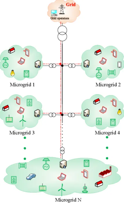
Figure 7: Concept of multi-microgrid.
regarding microgrids in the literature. One of these is a hybrid microgrid, which is often used in literature
to indicate a combination of different types of DGs (diesel, PV, wind and battery) [91, 92, 93, 94]. However,
this cannot be considered as a hybrid microgrid because a microgrid itself consists of these DGs by definitions. 345
Some other incorrect terms are CCHP microgrid, standalone PV microgrid, hybrid PV-CSP-LPG microgrid,
hybrid photovoltaic-battery-hydropower microgrid, hybrid multi-microgrid and multi-bus microgrid system [95,
96, 97, 98, 99, 100]. It is worth mentioning that the emerging active distribution network (ADN) has lots of
microgrid features, such as power electronic devices including Soft Open Point (SOP) which are used to realise
voltage and power regulation, and part of the distribution system can be operated in islanded mode, but it is 350
not considered as a microgrid unless a central control unit is used.
Remark 1: The term ‘and/or’ is added to the microgrid definition to include all types of microgrids, for
example, islanded and tied ones. ’And’ does not cover an islanded microgrid due to its lack of
grid-connection facilities whereas ’or’ refers to one mode of a microgrid operation, i.e., either grid-tied or islanded.
4.4. Microgrid classification 355
4.4.1. Classification of microgrids based on power supply
Microgrids are classified in three categories based on the characteristics of power they inject into a
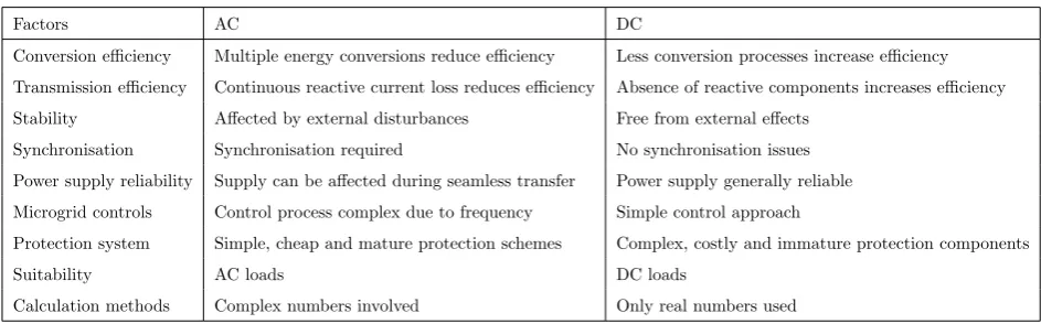
Table 6: Comparison of ac and dc microgrids.
Factors AC DC
Conversion efficiency Multiple energy conversions reduce efficiency Less conversion processes increase efficiency
Transmission efficiency Continuous reactive current loss reduces efficiency Absence of reactive components increases efficiency
Stability Affected by external disturbances Free from external effects
Synchronisation Synchronisation required No synchronisation issues
Power supply reliability Supply can be affected during seamless transfer Power supply generally reliable
Microgrid controls Control process complex due to frequency Simple control approach
Protection system Simple, cheap and mature protection schemes Complex, costly and immature protection components
Suitability AC loads DC loads
Calculation methods Complex numbers involved Only real numbers used
AC microgrids: AC microgrids represent the ac power supply in a distribution network. They can be
easily connected to an existing grid utility without special requirements such as converters and their control 360
approaches. Since the evolution of the microgrid concept, ac microgrids have occupied a central place in research,
with several publications regarding their control and operational approaches reported in the literature [101,
102, 103]. This is because of well-established ac power networks with compatible modes of electrical and
electronic devices. The distribution system of an ac microgrid can principally be classified as one of three
types, single-phase or three-phase with/without neutral-point lines. 365
DC microgrids: The concept of a dc microgrid, which has a better short circuit protection with enhanced
efficiency, has emerged due to the extensive application of modern electronic equipment and the availability
of environmentally friendly dc sources (solar and fuel cells). These microgrids exhibit higher efficiency and
have a lower conversion process for the application of dc loads than ac microgrids. Commercial applications
(telecommunication systems, shipboard power systems and electric vehicles (EVs)) of an LV dc distributed 370
power system are reported in [104, 105, 106, 107]. The distribution network of a dc microgrid can be one of
three types: monopolar; bipolar; or homopolar. The main difference between ac and dc microgrids is presented
in Table 6.
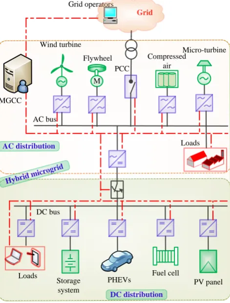
Hybrid microgrids: Hybrid microgrids consist of both ac and dc electricity distribution networks with an
MGCC as shown in Figure 6. The purposes of constructing hybrid microgrids are to minimise conversion stages, 375
reduce interfacing devices, increase reliability and reduce energy costs, thereby improving the overall efficiency
of the network. Such a structure enables both ac and dc power to be supplied to a distribution network while
clients can use electricity according to their needs (ac or dc). Usually, PECs are responsible for decoupling the
ac and dc parts of a microgrid [108, 109, 110].
4.4.2. Classification of microgrids based on location 380
Microgrids can be further classified based on their locations as urban or remote as shown in Figure 8, brief
descriptions of which are given below.
Urban microgrids: These microgrids are generally connected to a grid utility and, therefore, are capable of
exchanging power with the grid through PCC. These microgrids, also known as the grid-connected microgrids,
are capable of operating as an islanded microgrid during unusual situations, such as degraded power quality, 385
faults on the main grid and the undertaking of network maintenance [4, 111]. In these microgrids, all the
Microgrid classifications
Based on location Based on distribution system
Urban microgrids Remote microgrids AC microgrids DC microgrids Hybrid microgrids
Figure 8: Classifications of microgrids.
maintain the power quality of the grid and preserve the microgrids’ integrity for network stability. These types
of microgrids can be constructed in both residential and commercial premises, such as university campuses,
hospitals, data centres, communities, industries and shopping malls. 390
Remote microgrids: These microgrids are constructed in remote areas where a grid utility has no access
for geographical reasons, such as military installations, islands and hilly areas [1, 112]. As these microgrids, also
known as islanded microgrids, are not connected to the grid supply, they do not require rules and regulations
like urban microgrids. They are not as common as urban microgrids due to the lack of investment in them,
and economic, political and technological reasons, with remote and island communities their prime locations. 395
4.5. Challenges and opportunities of converter-based microgrids
In a traditional power system, output power of a large generator can be controlled according to power
demand, and the rotor of it are rotated at a constant speed, thereby obtaining a fixed network frequency.
However, most DG technologies generate uncontrolled power with different voltage magnitudes and frequencies.
As this process is quite different from that of the conventional power generation, it is challenging to integrate 400
DG units in a distribution network. To achieve this, PECs play a vital role by minimising harmonics and
generating the required voltage, frequency and power [113, 114, 115]. Although discussing all the microgrid
issues in detail is beyond the scope of this study, a few recently published articles are presented to provide a
comprehensive review of the overall challenges of microgrids.
4.5.1. Challenges of microgrids 405
A microgrid is different from a distribution network and has both additional advantages and challenges,
with a major difference its application of an energy management system or centralised control unit in a defined
region. In an islanded microgrid, which is not connected to a grid utility due to the geographical area, this
control unit is used to maintain a network’s optimal operation. However, in a grid-connected one, it has
the additional requirements to protect against islanding, synchronise with the grid utility and disconnect the 410
microgrid.
Microgrid central controller (MGCC):An MGCC is a physical computer system consisting of a
soft-ware platform in which various modules for generation and load forecasts, human machine interfaces and
supervisory control and data acquisition (SCADA) are used [116]. It executes several processes for forecasting
power generation, power demand and electricity market prices, and monitoring, analysing and optimising data, 415
optimal decisions in order to ensure a power supply at the minimum cost. An MGCC can be realised for the
both centralised and decentralised information processing. In a centralised processing, the central controller
processes all the information of a microgrid while, in a decentralised controller, the central controller takes into
account only a limited number of information with the real-time operation [117]. 420
An MGCC is essential for coordinating a microgrid’s different components in a systematic way to ensure its
secure, reliable and economical operation. It enables a distribution network to integrate a high penetration of
RESs and control them in an optimal way while the microgrid is either grid-connected or islanded. As its control
approach is the key element of a microgrid, it needs to be designed in a way that represents the microgrid as a
single entity from the grid perspective. Generally, a hierarchical control approach, in which primary, secondary 425
and tertiary control levels are embedded, is responsible for its coordination [4, 118, 119]. The role of the
primary control level is to ensure proper power sharing among DG units and control the terminal voltage
while those of the secondary and tertiary ones enable optimal operation of the microgrid considering multiple
objectives. Conventionally, these three levels, which incur a heavy computational burden and considerable costs
while providing low reliability due to a single point of failure, send necessary signals through low-bandwidth 430
communication lines to all the DG units. However, due to the development of advanced control approaches,
the primary and secondary control levels can be implemented in decentralised ways, e.g., in a local DG unit
controller (Figure 10), to enhance a microgrid’s reliability during a single point of failure.
To avoid expensive communication lines and increase the reliability of power sharing, the primary control
level generally adopts the droop control concept and the secondary one a MAS in a distributed manner to restore 435
the voltage and frequency [120, 121]. In MAS technologies, local controllers can make decisions autonomously
regarding controlling their own DG units by communicating with neighbouring ones. A distributed peer-to-peer
MAS for improving power sharing among DG units in a microgrid is demonstrated in [120]. An ontology-driven
MAS for implementing the energy management of microgrids considering DG units and non-critical loads is
presented in [122]. A review of MAS technologies used for microgrid control and optimisation is provided in 440
[8]. Although a MAS framework can work in a grid-connected microgrid, it may not do so effectively during
an islanded operation.
Although the primary and secondary control levels can be implemented in a decentralised manner to increase
the reliability of a microgrid, it is important to have a centralised tertiary control level for each microgrid to
coordinate it with other microgrids and the grid utility as well as provide optimal energy management of DG 445
units in the presence of a high penetration of RESs [123]. An MGCC detects the power quality at the PCC
to determine whether to operate in an islanded or grid-connected mode and can re-synchronise an islanded
microgrid with the grid utility once the grid restores the appropriate power quality [124, 125]. As the different
features of the energy sources in a microgrid produce fluctuating power levels which create challenges for
an MGCC to balance the power in a network, various control methods for an MGCC are proposed in the 450
literature [126, 127, 128, 129]. Balancing the power to avoid voltage fluctuations is an essential task of a
microgrid for its safe and reliable operation. An autonomous load-curtailment algorithm for disconnecting
loads during peak-load hours to minimise the power difference between supply and demand is developed in
[128]. An algorithm which optimises the power generation of a microgrid and its exchange of power with the
grid utility is proposed in [127]. As energy storage units are responsible for regulating the voltage’s amplitude 455
Human-machine Interface (using SCADA system)
Monitoring
Analysis
Control
Measured/
C
ommanded
data
Command to
Battery On/Off and charge/ discharge control Generator On/Off and
power control providing reference values Controllable loads (On/Off/
Shift)
Import/export power
S
hor
t-te
rm
f
or
ec
as
t
Grid
MGCC
Historical Data for Forecasting (24 hours) using forecasting techniques
Electricity prices
Power generation
Power demand
Day-ahead Scheduling (24 hour) using optimisation algorithms
Unit commitment
Economic dispatch
Short-term/Real-time Dispatch (may or may not optimisation algorithms) Optimisation stage
Figure 9: Typical stages of supervisory controller.
limits to prevent its fast degradation or damage is proposed in [129]. This method avoids the overcharging of
these units by curtailing their generation of active power, their deep discharging through load shedding and
their uneven degradation through equalising the charge state among the units.
Microgrid stability: In a conventional power system, stability problems that define the ability of a power 460
system to maintain synchronism during disturbances are categorised into rotor angle stability, voltage stability
and frequency stability [55]. While rotor-angle stability provides information regarding the balance between
the electro-magnetic and mechanical torques of a generator rotor required for it to remain in synchronism,
voltage and frequency stabilities refer to the balance of a network’s power supply and demand. Although the
dynamic behaviour of a synchronous generator has a substantial role in maintaining power system stability, in 465
a microgrid with converter-interfaced DGs, rotor angle stability is no longer an issue due to the lack of inertia
of DGs that makes a significant difference in operating a microgrid from the traditional grid [1]. In addition, a
microgrid also suffers from the buffer energy of an inter-connected transmission system where energy is stored
in the inductance and capacitance of line parameters. Although the voltage and frequency stabilities in a
microgrid are analysed in an islanded mode, only the former is controlled in a grid-tied operation due to the 470
small effect of the frequency on the grid [7] because the voltage acts as a local variable and the frequency as
VSI
Cd
c
L
C
DC Busbar μ-Grid Pac
δ vg iL PWM Energy Sources Secondary
control Primary and inner controls 𝑉
𝜔 𝛿𝑉
𝛿𝜔 𝑃∗𝑄∗
𝑃𝑚
𝑄𝑚 iL
δ vg 𝑉 𝜔 PCC 𝑉𝑠∗𝜔𝑠∗ Decentralised controls Grid Power calculation Low pass filter 𝑃𝑚
𝑄𝑚 iL
vg
Information exchange with neighbouring microgrids and grid utility
Forecasting of power generation, demand and electricity prices Operational limits and constraints
Feedback from the network parameters
Centralised EMS
𝜔𝑠∗ 𝑉𝑠∗
DG1
Set-points for microgrid parameters 𝜔 𝑠 ∗ 𝑉 𝑠 ∗ D G 1 D G n D G 2 PCC
Figure 10: Centralised and decentralised controls of microgrids.
stability of a microgrid basically dependent on its operational modes, control topology, types of DGs and loads,
and network parameters [130, 131, 132].
A small-disturbance analysis involves evaluating a microgrid’s stability in terms of linearising the system 475
around its operating points using eigenvalue analysis, Routh-Hurwitz or Nyquist stability criteria. Several
small-signal analyses that deal with load fluctuations, and the influence of droop gains and variations in the
line impedance on voltage and frequency characteristics are conducted in [130, 133, 134, 131, 135, 61, 62].
As droop coefficients have a direct influence on a microgrid’s small-signal stability, accurate design of droop
coefficients and a droop control with adjustable dynamic behaviour are recommended in [61, 62, 136]. A small-480
signal analysis of a grid-connected inverter for use in an UPS unit is first demonstrated in [137]. Then, in [61],
inverter-based microgrids with linear loads are modelled to perform a small-signal analysis of the frequency and
damping of oscillatory components. To demonstrate the influence of an active load in a microgrid, in [62], a
network is modelled with non-linear loads and it is found that the low-frequency modes are linked to the voltage
controller of the active rectifier and the large load gains cause instability in the inverter’s operation. In [63], 485
a synchronous generator is added to an inverter-based microgrid to investigate the stability margin, with a
modified droop control presented. A reduced-order model using the Kron reduction method for inter-inverter
oscillations is developed in [138]. In [139], inertia constant and frequency droop coefficients are tuned together
by applying the knee-point-driven evolutionary algorithm (KnEA) to enhance the stability of the frequency of
a microgrid. The main disadvantage of a small-signal analysis is that it is only effective around the linearised 490
operating points and does not indicate the ranges. However, this can be overcome by implementing non-linear
techniques such as Lyapunov methods. To achieve improved performances, researchers can still obtain an
A large-disturbance stability analysis determines a system’s capability to retain a network’s stability after a
large change, such as a fault, switching of the operating mode or loss of generators or loads, in it. Although this 495
has been extensively used for conventional power systems, there is little information in the literature regarding
that for a microgrid. The transient stability determines mainly the dynamic responses of different types of
DGs, characteristics of the fault current’s contribution and transient behaviour of a microgrid. In [132], the
dynamic behaviour of a doubly-fed induction generator (DFIG) is analysed using a fifth-order model while, due
to complications caused by the presence of several DFIGs, a simplified model is presented in [140]. A model 500
for a grid-tied PV system for analysing the transient response under a large disturbance is implemented in
[141]. In [142], a comparative study of PV systems shows that distributed PV generators have more advantages
in terms of stability than solar farms. In a study of the transient stability of DG units, it is observed that
the stability is greatly affected by a current limiter used to protect these units against damage [143]. In
[144], a virtual power-angle instability considering an active power disturbance is analysed using the virtual 505
power-angle curves of a converter connected to an infinity bus. In [145], as an extension of previous work, the
large-disturbance stability of a droop-controlled DG unit is theoretically studied based on complicated dynamic
behaviour. A 13th-order non-linear model of a dc/ac converter for gaining insights into the transient stability
of converter-based microgrids is developed in [146].
The stability of microgrids can be improved in various ways, such as by using control strategies, reactive 510
power compensations, storage systems and shedding loads [147]. Although a high droop gain can enable a
proper load sharing, it may cause instability in microgrids while a microgrid’s stability is improved by optimising
the droop gains and using a supplementary loop [148, 149, 150]. In [151], an extra inverter is connected in
parallel with DGs to inject reactive power during a voltage dip to improve the stability and LV ride through
of a microgrid. An ESS can be used to support a sudden change in the mode transfer or load shedding of 515
a microgrid to improve stability. An overview of a microgrid’s stability issues and mitigation procedures is
presented in Figure 11. It is worth mentioning that a microgrid’s stability is divided into mainly frequency
and voltage stabilities. The small- and large-disturbance stability are categorised as analysing methods not the
types of stabilities reported in [7, 147]. While the majority of research presented to date is based on radial
Figure 11: Pictorial overview of microgrid’s stability issues and mitigation procedures.
networks, studies of the stability of mesh ones are still needed. 520
Protection: A conventional distribution network, the current flow of which is unidirectional, is equipped
with protection devices, such as reclosers, circuit breakers, fuses and relays, to ensure fault detection and
a radial network makes the network a complicated one due to the difficulty of analysing the direction and
magnitude of the bidirectional current flow [152]. In addition, DG units in a microgrid need to be protected in 525
both grid-connected and islanded operations, where a fault current changes significantly for altering the modes.
The reason is that the utility supports a huge flow current in a grid-tied microgrid, whereas converter-interfaced
DG units limit the fault current during an islanded operation due to stochastic nature of power generation and
power limits of electronic components [153]. This limit may be so low that conventional protection systems,
such as fuses, over-current relays and reclosers, may not accurately detect faults due to their pre-set current 530
limits and, consequently, may be inadequate for completely protecting a microgrid. A fault current is affected
by the capacities, types and locations of DG units which may cause miscoordination among primary backup
relays and lead to the false tripping of protection devices, unintentional islanding, failure of auto-reclosing and
fault detection [154]. Therefore, it is essential to design a proper protection scheme that can be operated under
different microgrid conditions. 535
The microgrid protection system can be classified into two types, 1) a static switch at the PCC of the
microgrid to first isolate the microgrid from the distribution network in spite of internal or external faults of
the microgrid; 2) the microgrid protection system which contains two different individual protection functions,
one for the grid-connected operation mode and the other one for the islanded operation mode. Several protection
methods for solving protection issues are proposed in the literature. One is changing the protective devices or 540
settings by re-calculating them according to changes in the network’s topology [155, 156, 157, 158]. Its main
drawback is that it does not consider an increasing penetration of DG units, uncertainties inherent in power
generation and demand, and reconfiguration of the network [159]. A fault current limiter (FCL), in which a
limiter (impedance) is connected in a series with DG units, is another approach for minimising the effects of
the units on the protection system [160, 161, 162]. In a normal operation, the value of impedance is almost 545
zero but rises and limits the short-circuit current when a fault is detected. Although this method can reduce
the negative impact of installing DG units, it is only applicable for specific types of microgrid topologies due
to its expense and need to select the best location for the series impedance for every microgrid configuration.
To overcome the above issues, an adaptive protection scheme which changes the parameters of protective
devices via communication or measurements in response to a change in a microgrid’s configuration is presented 550
in [163]. It constantly monitors the system’s status using a communication channel to update the coordination
of its protection devices during changes in its operations or topology. It consists of directional over-current
relays with a changeable group of settings and high-speed, secure communication channels. It can be operated
in both a centralised and decentralised manner whereby a microgrid’s protective settings are updated either
online or offline for each change in its topology [164]. In an offline process, all possible settings for different 555
scenarios in a microgrid’s grid-tied and islanded modes are first stored in a memory of a supervisory remote
control unit (SRCU), then it analyses the microgrid’s status to decide the settings of online relays for any
change in the network’s topology [165]. However, an offline method may not work for all dynamic situations
and simultaneous faults due to a large number of conditions [166].
A SRCU is used in a centralised adaptive protection scheme to adjust relay settings to obtain an appropriate 560
current level via a high-speed, secure communicative infrastructure while a decentralised one, in which a set of
distribution agents of various devices is operated in a coordinated way through communication channels, has a

![Table 5: Some research projects conducted on microgrids [81].](https://thumb-us.123doks.com/thumbv2/123dok_us/7962168.1320768/12.595.55.560.156.437/table-research-projects-conducted-microgrids.webp)