System Manual
1200362L1 NetVanta 2050 System 1200361L1 NetVanta 2100 System 1200366L1 NetVanta 2300 System 1200367L1 NetVanta 2400 System
trade names of their respective holders.
To the Holder of the Manual
The contents of this manual are current as of the date of publication. ADTRAN reserves the right to change the contents without prior notice.
In no event will ADTRAN be liable for any special, incidental, or consequential damages or for commercial losses even if ADTRAN has been advised thereof as a result of issue of this publication.
901 Explorer Boulevard P.O. Box 140000 Huntsville, AL 35814-4000
Phone: (256) 963-8000
©2001 ADTRAN, Inc. All Rights Reserved.
purpose of this manual is to provide the technician, system administrator, and manager with general and specific information related to the planning, installation, operation, and maintenance of the NetVanta 2000 series. This manual is arranged so that needed information can be quickly and easily found. The following is an overview of the contents.
Section 1
System Description
Provides managers with an overview of the NetVanta 2000 series system.
Section 2
Engineering Guidelines
Provides information to assist network designers with incorporating the NetVanta 2000 series system into their networks.
Section 3
Network Turnup Procedure
Provides step-by-step instructions on how to install the NetVanta 2000 series unit, determine the parameters for the system, install the network and option modules, and power up the system.
Section 4
User Interface Guide
A reference guide listing all menu options contained in the NetVanta 2000 series.
Section 5
Detail Level Procedures
Provides the Provides the Detail Level Procedures to perform various unit functions (upgrading firmware, telnet, etc). Level Procedures called out in Section 3.
Glossary and Acronyms
Gives definitions of terms and acronyms used in the manual.
Revision History
This is the 4th issue of this manual. Revisions include:
Safety Instructions
When using your telephone equipment, please follow these basic safety precautions to reduce the risk of fire, electrical shock, or personal injury:
1. Do not use this product near water, such as a bathtub, wash bowl, kitchen sink, laundry tub, in a wet basement, or near a swimming pool.
2. Avoid using a telephone (other than a cordless-type) during an electrical storm. There is a remote risk of shock from lightning.
3. Do not use the telephone to report a gas leak in the vicinity of the leak.
4. Use only the power cord, power supply, and/or batteries indicated in the manual. Do not dispose of batteries in a fire. They may explode. Check with local codes for special disposal instructions.
Save These Important Safety Instructions
Cautions signify information that could prevent service interruption.to Part 15 of the FCC Rules. These limits are designed to provide reasonable protection against harmful interference when the equipment is operated in a commercial environment. This equipment generates, uses, and can radiate radio frequency energy and, if not installed and used in accordance with the
instruction manual, may cause harmful interference to radio frequencies. Operation of this equipment in a residential area is likely to cause harmful interference in which case the user will be required to correct the interference at his own expense.
Canadian Emissions Requirements
This digital apparatus does not exceed the Class A limits for radio noise emissions from digital apparatus as set out in the interference-causing equipment standard entitled “Digital Apparatus,” ICES-003 of the Department of Communications.
Cet appareil numérique respecte les limites de bruits radioelectriques applicables aux appareils numériques de Class A prescrites dans la norme sur le materiel brouilleur: “Appareils Numériques,” NMB-003 edictee par le ministre des Communications.
Shielded cables must be used with this unit to ensure compliance with Class A FCC limits.
means that the equipment meets certain telecommunications network protective, operational, and safety requirements. The Department does not guarantee the equipment will operate to the user’s satisfaction.
Before installing this equipment, users should ensure that it is permissible to be connected to the facilities of the local telecommunications company. The equipment must also be installed using an acceptable method of connection. In some cases, the company’s inside wiring associated with a single line individual service may be extended by means of a certified connector assembly (telephone extension cord). The customer should be aware that compliance with the above limitations may not prevent degradation of service in some situations.
Repairs to certified equipment should be made by an authorized Canadian maintenance facility designated by the supplier. Any repairs or alterations made by the user to this equipment, or equipment malfunctions, may give the telecommunications company cause to request the user to disconnect the equipment.
Users should ensure for their own protection that the electrical ground connections of the power utility, telephone lines and internal metallic water pipe system, if present, are connected together. This precaution may be particularly important in rural areas.
The Load Number (LN) assigned to each terminal device denotes the percentage of the total load to be connected to a telephone loop which is used by the device, to prevent overloading. The termination on a loop may consist of any combination of devices subject only to the requirement that the total of the Load Numbers of all devices does not exceed 100.
its published specifications or fails while in service. For detailed warranty, repair, and return information refer to the ADTRAN Equipment Warranty and Repair and Return Policy Procedure.
Return Material Authorization (RMA) is required prior to returning equipment to ADTRAN.
For service, RMA requests, or further information, contact one of the numbers listed at the end of this section.
LIMITED PRODUCT WARRANTY
ADTRAN warrants that for five years from the date of shipment to Customer, all products manufactured by ADTRAN will be free from defects in materials and workmanship. ADTRAN also warrants that products will conform to the applicable specifications and drawings for such products, as contained in the Product Manual or in ADTRAN's internal specifications and drawings for such products (which may or may not be reflected in the Product Manual). This warranty only applies if Customer gives ADTRAN written notice of defects during the warranty period. Upon such notice, ADTRAN will, at its option, either repair or replace the defective item. If ADTRAN is unable, in a reasonable time, to repair or replace any equipment to a condition as warranted, Customer is entitled to a full refund of the purchase price upon return of the equipment to ADTRAN. This warranty applies only to the original purchaser and is not transferable without ADTRAN's express written permission. This warranty becomes null and void if Customer modifies or alters the equipment in any way, other than as specifically authorized by ADTRAN.
EXCEPT FOR THE LIMITED WARRANTY DESCRIBED ABOVE, THE FOREGOING CONSTITUTES THE SOLE AND EXCLUSIVE REMEDY OF THE CUSTOMER AND THE
EXCLUSIVE LIABILITY OF ADTRAN AND IS IN LIEU OF ANY AND ALL OTHER WARRANTIES (EXPRESSED OR IMPLIED). ADTRAN SPECIFICALLY DISCLAIMS ALL OTHER WARRANTIES, INCLUDING (WITHOUT LIMITATION), ALL WARRANTIES OF MERCHANTABILITY AND FITNESS FOR A PARTICULAR PURPOSE. SOME STATES DO NOT ALLOW THE EXCLUSION OF IMPLIED WARRANTIES, SO THIS EXCLUSION MAY NOT APPLY TO CUSTOMER.
does not meet its published specification or the product fails while in service.
A return material authorization (RMA) is required prior to returning equipment to ADTRAN. For service, RMA requests, training, or more information, use the contact information given below.
Repair and Return
If you determine that a repair is needed, please contact our Customer and Product Service (CAPS) department to have an RMA number issued. CAPS should also be contacted to obtain information regarding equipment currently in house or possible fees associated with repair.
Identify the RMA number clearly on the package (below address), and return to the following address:
Pre-Sales Inquiries and Applications Support
Your reseller should serve as the first point of contact for support. If additional pre-sales support is needed, the ADTRAN Support web site provides a variety of support services such as a searchable knowledge base, latest product documentation, application briefs, case studies, and a link to submit a question to an Applications Engineer. All of this, and more, is available at:
When needed, further pre-sales assistance is available by calling our Applications Engineering Department.
CAPS Department (256) 963-8722
ADTRAN Customer and Product Service 901 Explorer Blvd. (East Tower)
Huntsville, Alabama 35806
RMA # _____________
http://support.adtran.com
ADTRAN Support web site provides a variety of support services such as a searchable knowledge base, updated firmware releases, latest product documentation, service request ticket generation and
trouble-shooting tools. All of this, and more, is available at:
When needed, further post-sales assistance is available by calling our Technical Support Center. Please have your unit serial number available when you call.
Installation and Maintenance Support
The ADTRAN Custom Extended Services (ACES) program offers multiple types and levels of installation and maintenance services which allow you to choose the kind of assistance you need. This support is available at:
For questions, call the ACES Help Desk.
Training
The Enterprise Network (EN) Technical Training Department offers training on our most popular products. These courses include overviews on product features and functions while covering applications of
ADTRAN's product lines. ADTRAN provides a variety of training options, including customized training and courses taught at our facilities or at your site. For more information about training, please contact your Territory Manager or the Enterprise Training Coordinator.
http://support.adtran.com
Technical Support (888) 4ADTRAN
http://www.adtran.com/aces
ACES Help Desk (888) 874-ACES (2237)
Training Phone (800) 615-1176, ext. 7500
Training Fax (256) 963-6700
C
ONTENTSSystem Overview . . . 12
Features and Benefits . . . 13
Physical Interfaces . . . 13
Firewall Features. . . 13
Address Translation . . . 13
IPSec Tunnel. . . 13
Administration . . . 13
DHCP . . . 14
PPPoE. . . 14
1.
SYSTEM OVERVIEW
The NetVanta 2000 series of VPN products include small to mid-range IPSec compliant gateways
providing all the necessary components required to secure an integrated VPN solution. Used primarily for remote access and site-to-multisite connectivity, the NetVanta 2050 and NetVanta 2100 targets the
corporate branch office, the small office/home office (SOHO), as well as business-to-business
applications. As a branch office or mid-size host security gateway, the NetVanta 2300 provides the same features as the NetVanta 2100 with an added DMZ port for public server access. For networks supporting a large VPN network, the NetVanta 2400 is available to provide all necessary host site gateway functionality. The NetVanta 2000 series provides several key security and data management features such as IPSec VPN tunneling, stateful inspection firewall (providing cyber assault protection), authenticated remote user access, and Network Address Translation. Adhering to IPSec standards (established and maintained by the IETF) enables the NetVanta 2000 series to be interoperable with many other IPSec compliant gateways, allowing for a multi-vendor VPN solution.
On a public infrastructure like the Internet, security is of the utmost importance. The NetVanta 2000 series protect the corporate network against attacks with a built in firewall and provides data security through encryption, authentication and key exchange. The NetVanta 2000 series employ a stateful inspection firewall that protects an organization's network from common cyber attacks including TCP syn-flooding, IP spoofing, ICMP redirect, land attacks, ping-of-death, and IP reassembly problems.
For encryption, the NetVanta 2000 series encrypt the data being sent out onto the network, using either the Data Encryption Standard (DES) or 3DES encryption algorithms. Data integrity is ensured using MD5 or SHA1 as it is transported across the public infrastructure. In addition, Internet Key Exchange (IKE) can be used for user authentication supporting public and private keys or digital certificates, assuring that the proper VPN tunnel is established and that the tunnel has not been redirected or compromised.
NetVanta 2000 series are Internet Protocol Security (IPSec) compliant devices that supports both ESP and AH protocols and provides secure communication over potentially unsecure network components. Acting as a security gateway, the NetVanta 2050 and 2100 can provide up to 10 private encryption communication tunnels through the Internet with remote locations while the larger scale NetVanta 2300 offers support for up to 100 private encryption tunnels. For networks requiring more than 100 tunnels, the NetVanta 2400 provides 1000 private encryption tunnels. The NetVanta 2000 series can also hide IP addresses from the external world by performing Network Address Translation (NAT). The internal router allows multiple users to share a VPN connection and can also direct incoming IP traffic.
A remote NetVanta 2000 series can easily be configured and managed using a standard web browser. NetVanta 2000 series also have built-in alert and logging mechanisms for messaging and mail services. This enables the unit to warn administrators about activities that are going on in the network by logging them into a Syslog server or sending an email to the administrator.
2.
FEATURES AND BENEFITS
The NetVanta 2000 series provide granular control over network access that includes maximum security, data authenticity and privacy, and significant ease of use. The major features of the NetVanta 2000 series are described below.
Physical Interfaces
• WAN: RJ-45 10/100 Auto-sensing ethernet interface • LAN: RJ-45 10/100 Auto-sensing ethernet interface
• Serial Port: RS-232 for off-net configuration (NetVanta 2300 Only) • DMZ: RJ-45 10/100 Auto-sensing ethernet interface
Firewall Features
• Stateful inspection firewall • Application content filtering • Cyber assault protection • HTTP relay
Address Translation
• Basic NAT (1:1) • NAPT (Many:1)
• Reverse NAT (translation of an inbound session’s destination IP address)
IPSec Tunnel
• Encapsulating Security Payload (ESP) • Authentication Header (AH)
• Manual key management or automatic key management using Internet Key Exchange (IKE) • X.509 certificate support
• MD5-HMAC 128-bit authentication algorithm • SHA1-HMAC 160-bit authentication algorithm • DES-CBC 56-bit encryption
• 3DES-CBC 168-bit encryption
Administration
• Web-based management
• Syslog logging in WELF format • E-mail alerts (SMTP)
DHCP
• Server (to manage IP addresses on local network)
• Client (to acquire the WAN-side IP address from service provider)
PPPoE
• Client (to acquire the WAN-side IP address from service provider)
Routing
C
ONTENTSEquipment Dimensions . . . 16
Power Requirements . . . 16
Reviewing the front Panel Design . . . 16
Front Panel LEDs . . . 17
Reviewing the Rear Panel Design . . . 18
LAN Interface . . . 19
WAN Connection. . . 19
DMZ Connection (NetVanta 2300 Only) . . . 20
COM1 Interface. . . 21
Power Connection. . . 21
At-A-Glance Specifications . . . 22
F
IGURES Figure 1. NetVanta 2000 series Front Panel Layout . . . 16Figure 2. NetVanta 2300 Front Panel Layout . . . 17
Figure 3. NetVanta 2000 series Rear Panel Layout . . . 18
Figure 4. NetVanta 2300 Rear Panel Layout . . . 19
T
ABLES Table 1. NetVanta 2000 series Front Panel Description . . . 17Table 2. NetVanta 2000 series LEDs . . . 17
Table 3. LAN Pinout . . . 19
Table 5. DMZ Pinout . . . 20
Table 4. WAN Pinout . . . 20
Table 6. DB-9 Connector Pinout . . . . 21
1.
EQUIPMENT DIMENSIONS
NetVanta 2050 and 2100
The NetVanta 2050 and 2100 units are 9.0” W, 6.375” D, and 1.625” H and come equipped for table top and wallmount use. An optional rackmount shelf is available from ADTRAN.
NetVanta 2300 and 2400
The NetVanta 2300 units are17.25" W, 7.75" D, and 1.26" H and come equipped for rackmount use.
2.
POWER REQUIREMENTS
NetVanta 2050 and 2100
The NetVanta 2000 series has a maximum power consumption of 9W and a maximum current draw of 800mA.
NetVanta 2300 and 2400
The NetVanta 2300 has a maximum power consumption of 11W and a maximum current draw of 0.2A.
3.
REVIEWING THE FRONT PANEL DESIGN
NetVanta 2050
The NetVanta 2100 front panel monitors operation by providing status LEDs for both the LAN and WAN interfaces, as well as VPN tunnels and traffic. The front panel is shown in Figure 1.
Figure 1. NetVanta 2050 Front Panel Layout PWR STAT TD
VPN
RD TD RD TD RD
NetVanta 2050
WAN LAN
PWR STAT TD VPN
RD TD RD
NetVanta 2050
NetVanta 2100
The NetVanta 2100 front panel monitors operation by providing status LEDs for both the LAN and WAN interfaces, as well as VPN tunnels and traffic. The front panel is shown in Figure 2.
Figure 2. NetVanta 2100 Front Panel Layout
NetVanta 2300
The NetVanta 2300 front panel monitors operation by providing status LEDs for the LAN, WAN, and DMZ interfaces, as well as VPN tunnels and traffic. The front panel is shown in Figure 3.
Figure 3. NetVanta 2300 Front Panel Layout
NetVanta 2400
The NetVanta 2300 front panel monitors operation by providing status LEDs for the LAN, WAN, and DMZ interfaces, as well as VPN tunnels and traffic. Additionally, a LCD display provides quick-glance access to the LAN IP parameters (IP address and subnet mask). The front panel is shown in Figure 4.
Figure 4. NetVanta 2400 Front Panel Layout PWR STAT TD
VPN
RD TD RD TD RD
NetVanta 2100
WAN LAN
PWR STAT TD VPN
RD TD RD
WAN LAN STATUS POWER VPN TD RD ACT TD RD LNK TD RD LNK TD RD LNK WAN LAN DMZ
NetVanta 2300 2300
Front Panel LEDs
With the NetVanta 2000 series powered-up, the front panel LEDs provide visual information about the status of the system. Table 1 provides a brief description of the front panel features, and Table 2 provides detailed information about the LEDs.
Table 1. NetVanta 2000 series Front Panel Description
Feature Description
PWR Indicates whether the unit has power.
VPN (2050/2100 only) Indicates status of VPN negotiations.
VPN TD Indicates VPN traffic transmitted by the NetVanta. VPN RD Indicates VPN traffic received by the NetVanta. VPN ACT (2300/2400 only) Indicates status of VPN Negotiations.
LAN TD Indicates LAN traffic transmitted by the NetVanta. LAN RD Indicates LAN traffic received by the NetVanta. LAN LNK (2300/2400 Only) Indicates active physical link on the LAN port. WAN TD Indicates WAN traffic transmitted by the NetVanta. WAN RD Indicates WAN traffic received by the NetVanta. WAN LNK (2300/2400 Only) Indicates active physical link on the WAN port.
Table 2. NetVanta 2000 series LEDs For these LEDs... This color light... Indicates that...
PWR Red (solid) The unit has power and is in the boot process. Green (solid) Unit has power and has successfully completed the
boot process.
VPN
(2050/2100 only)
VPN ACT (2300/2400 Only)
Amber (slow blink) Initial Phase 1 IKE negotiation in progress.
Green (slow blink) Initial Phase 1 IKE negotiation completed successfully.
Red (slow blink) Phase 1 IKE negotiation failed.
Amber (fast blink) Phase 2 IKE negotiation in progress.
Green (solid) Phase 2 IKE negotiation completed successfully.
Red (fast blink) Phase 2 IKE negotiation failed.
Amber and Green (alternating slow blink)
4.
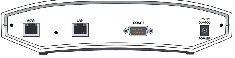
REVIEWING THE REAR PANEL DESIGN
NetVanta 2050 and 2100
The NetVanta 2050 and 2100 rear panel contains 2 Ethernet ports, a DB-9 serial connection, and a power connection (see Figure 5).
Figure 5. NetVanta 2050 Rear Panel Layout
VPN TD Green (blink) Flashes with VPN data transmitted by the NetVanta 2000 series.
VPN RD Green (blink) Flashes with VPN data received by the NetVanta 2000 series.
LAN TD Green (blink) Flashes with data transmitted on the LAN interface. LAN RD Green (blink) Flashes with data received on the LAN interface. LAN LNK
(2300/2400 Only) Green (solid) Unit has active physical connection on the LAN interface. WAN TD Green (blink) Flashes with data transmitted on the WAN interface. WAN RD Green (blink) Flashes with data received on the WAN interface. WAN LNK
(2300/2400 Only) Green (solid) Unit has active physical connection on the WAN interface. Table 2. NetVanta 2000 series LEDs (Continued)
For these LEDs... This color light... Indicates that...
POWER
WAN LAN
NetVanta 2300
The NetVanta 2300 rear panel contains 3 Ethernet ports, a DB-9 serial connection, and a power connection (see Figure 6).
Figure 6. NetVanta 2300 Rear Panel Layout
NetVanta 2400
The NetVanta 2300 rear panel contains 3 Ethernet ports, a DB-9 serial connection, a power connection and ventilation openings (see Figure 7).
Figure 7. NetVanta 2400 Rear Panel Layout
LAN Interface
The NetVanta 2000 series provides a standard 10/100BaseT Ethernet interface for connection to the local corporate network. Connect the LAN interface to a hub located on your local corporate network. A DHCP Server is enabled on the LAN interface by default. References to the LAN interface include LAN, CORP, and Eth0
The LAN connection follows, and Table 3 shows the pinout.
Connector Type RJ-48C
Table 3. LAN Pinout Pin Name Description
1 TX1 Transmit Positive
2 TX2 Transmit Negative
3 RX1 Receive Positive
4, 5 UNUSED —
6 RX2 Receive Negative
7, 8 UNUSED —
WAN Connection
The NetVanta 2000 series provides a standard 10/100BaseT Ethernet interface for connection to the wide area network. Connect the WAN interface to a hub connected to the router interfacing with the non-secure Internet or the modem (cable or DSL) used for Internet access. A DHCP Client is enabled on the WAN interface by default. References to the WAN interface include Internet, WAN, and Eth1.
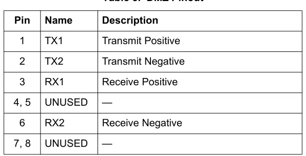
DMZ Connection (NetVanta 2300 and 2400 Only)
The NetVanta 2300 and 2400 provide a standard 10/100BaseT Ethernet interface for providing public server access. Table 5 shows the pinout for the DMZ port.
Connector Type (USOC) RJ-48C
Table 4. WAN Pinout Pin Name Description
1 TX1 Transmit Positive
2 TX2 Transmit Negative
3 RX1 Receive Positive
4, 5 UNUSED —
6 RX2 Receive Negative
7, 8 UNUSED —
Connector Type (USOC) RJ-48C
Table 5. DMZ Pinout Pin Name Description
1 TX1 Transmit Positive
2 TX2 Transmit Negative
3 RX1 Receive Positive
4, 5 UNUSED —
6 RX2 Receive Negative
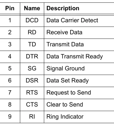
COM1 Interface
The NetVanta 2000 series provides a DB-9 serial communication port for future command line. Table 6 shows the pinout for the DB-9 connector.
Power Connection
NetVanta 2050 and 2100
The NetVanta 2000 series includes a 12 VDC power supply. Connect the power supply to a standard 120VAC, 60-Hz electrical outlet for proper operation.
NetVanta 2300 and 2400
The NetVanta 2300 and 2400 include an auto sensing 100-250 VAC, 50/60 Hz power supply with a three prong removable cable. Connect the power supply to a standard 120 VAC, 60 Hz or 220 VAC, 50 Hz electrical outlet for proper operation.
Connector Type DB-9
Table 6. DB-9 Connector Pinout Pin Name Description
1 DCD Data Carrier Detect
2 RD Receive Data
3 TD Transmit Data
4 DTR Data Transmit Ready
5 SG Signal Ground
6 DSR Data Set Ready
7 RTS Request to Send
8 CTS Clear to Send
5.
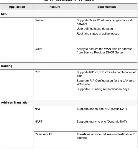
AT-A-GLANCE SPECIFICATIONS
Table 7 lists the specifications for the NetVanta 2000 series system.
Table 7. Specifications
Application Feature Specification
Firewall
Stateful Inspection Firewall Provides support against the following attacks: IP Spoofing, Land Attack, Ping of Death, and Reassembly Attack
Provides checks for the following attacks: ICMP Redirect, Syn Flooding, Winnuke, and Source Routing
IPSEC Tunnel
Encryption Encapsulating Security Payload (ESP) DES-CBC 56-bit encryption
3DES-CBC 168-bit encryption
Authentication Authentication Header (AH)
MD5-HMAC 128-bit authentication algorithm SHA1-HMAC 160-bit authentication algorithm
Certificate Support X.509 certificate support
IKE Manual key management for automatic key
DHCP
Server Supports three IP address ranges on local network
User defined lease duration Real time status of active leases
Client Ability to acquire the WAN-side IP address from Service Provider DHCP Server
Routing
RIP Supports RIP v1, RIP v2 and a combination of
both
Separate RIP Configuration for the LAN and WAN side
Supports RIP using Authentication Keys
Address Translation
NAT Supports one-to-one NAT (Static NAT)
NAPT Supports many-to-one (Dynamic NAT)
Reverse NAT Translates an inbound session destination IP address
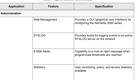
Table 7. Specifications (Continued)
Administration
Web Management Provides a GUI (graphical user interface) for configuring the NetVanta 2000 series
SYSLOG Provides levels for logging events to an active SYSLOG server on the network
E-Mail Alerts Capability to e-mail an alert message when programmed thresholds are reached
Statistics User monitoring, policy, and access statistics available
Table 7. Specifications (Continued)
C
ONTENTSIntroduction . . . 26 Tools Required . . . 26 Unpack and Inspect the SYSTEM . . . . 26 Contents of ADTRAN Shipments - NetVanta 2100. . . 26 Contents of ADTRAN Shipments - NetVanta 2300 . . . 26
1.
INTRODUCTION
This section discusses the installation process of the NetVanta 2000 series systems.
2.
TOOLS REQUIRED
The tools required for installation of the NetVanta 2000 series systems are: • CATV-UTP Ethernet cable to connect the unit to the existing network • An Internet browser for configuring the unit
3.
UNPACK AND INSPECT THE SYSTEM
Each NetVanta 2000 series unit is shipped in its own cardboard shipping carton. Open each carton carefully and avoid deep penetration into the carton with sharp objects.
After unpacking the unit, inspect it for possible shipping damage. If the equipment has been damaged in transit, immediately file a claim with the carrier, then contact ADTRAN Customer Service (see Customer Service, Product Support Information, and Training in the front of this manual).
Contents of ADTRAN Shipments - NetVanta 2050 and 2100
Your ADTRAN shipment includes the following items: • The NetVanta 2050 or 2100 Unit
• The NetVanta 2000 series User Manual CD (ADTRAN P/N 3253041) • AC Power supply - (ADTRAN P/N 336012 VUR01)
• Crossover Ethernet cable for connecting the NetVanta 2100 directly to a PC (ADTRAN P/N 8125M012)
Contents of ADTRAN Shipments - NetVanta 2300 and 2400
Your ADTRAN shipment includes the following items: • The NetVanta 2300 or 2400 Unit
• The NetVanta 2000 series User Manual CD (ADTRAN P/N 3253041) • AC Power cable (ADTRAN P/N 3127009)
• (2) Brackets for installing the unit in a rackmount configuration (ADTRAN P/N 3265479)
4.
SUPPLYING POWER TO THE UNIT
NetVanta 2050 and 2100
The AC powered NetVanta 2050 and 2100 come equipped with a detachable 12 VDC at 800 mA wallmount power supply for connecting to a grounded power receptacle. As shipped, the NetVanta 2050 and 2100 are set to factory default conditions. After installing the unit, the NetVanta 2050 and 2100 are ready for power-up. To power-up the unit, connect the unit to an appropriate power source.
NetVanta 2300 and 2400
The AC powered NetVanta 2300 adn 2400 come equipped with an auto-sensing 100-240 VAC, 50-60 Hz power supply for connecting to a grounded power receptacle. A grounded three plug detachable cable is included with the shipment. As shipped, the NetVanta 2300 and 2400 are set to factory default conditions. After installing the unit, the NetVanta 2300 and 2400 are ready for power-up. To power-up the unit, connect the unit to an appropriate power source.
5.
INSTALLING NETVANTA 2000 SERIES MANAGEMENT COMPONENTS
Configuring the NetVanta 2000 series unit through the web interface requires a host computer with an Ethernet interface and a web browser. ADTRAN recommends using Internet Explorer 5.0 or greater for optimal viewing of configuration web pages.
The NetVanta 2000 series of products contains a default IP address of 10.10.10.1 and a netmask of 255.255.255.0. Select an IP address in the same range as the NetVanta unit and assign it to the host computer running the web browser. An example IP address is 10.10.10.10 with a subnet mask of 255.255.255.0. This section contains detailed procedures for assigning the selected IP address to a host computer for each of the popular operating systems.
• This unit shall be installed in accordance with Article 400 and 364.8 of the NEC NFPA 70 when installed outside of a Restricted Access Location (i.e., central office, behind a locked door, service personnel only area).
• Power to the NetVanta 2050/2100 AC system must be from a grounded 90-130 VAC, 50/60 Hz source.
• The power receptacle uses double-pole, neutral fusing.
• Maximum recommended ambient operating temperature is 45 oC.
• This unit shall be installed in accordance with Article 400 and 364.8 of the NEC NFPA 70 when installed outside of a Restricted Access Location (i.e., central office, behind a locked door, service personnel only area).
• Power to the NetVanta 2300/2400 AC system must be from a grounded 100-240 VAC, 50/60 Hz source.
• The power receptacle uses double-pole, neutral fusing.
Browsing Hosts Running Microsoft Windows NT, Windows 2000, or Windows 98/95
1. Follow the menu path START>SETTINGS>CONTROL PANEL.
2. After the CONTROL PANEL appears, double-click the NETWORK icon to display the existing network
configuration.
3. Select TCP/IP from the list of installed network components. If there are multiple sessions, select the one for the Ethernet card in the host computer.
4. Click PROPERTIES, which shows the existing properties of the TCP/IP protocol running on the host
computer in a multi-paned window.
5. Select the IP ADDRESS pane by clicking on it.
6. Check the SPECIFYAN IP ADDRESS radio button.
7. Enter the IP ADDRESS as: 10.10.10.50 and SUBNET MASK as: 255.255.255.0.
8. Click OK to close the properties window.
9. Click OK on the network configuration window, which will ask you to reboot the browser computer.
10. Click YES to reboot your computer.
Browsing Hosts Running POSIX-Compliant UNIX
1. Log in as root, or change to superuser.
2. Run the ifconfig command -a option to list the configured network interfaces in the system. This will show the Ethernet interface name as well. For example:
#ifconfig -a
lo0: flags=863<UP,LOOPBACK,RUNNING,MULTICAST> mtu 8232 inet 127.0.0.1 netmask ff000000
hme0: flags=863<UP,BROADCAST,NOTRAILERS,RUNNING,MULTICAST> mtu 1500 inet 192.103.55.186 netmask ffffff00 broadcast 192.103.255.255
If you have a PC with DHCP client capabilities enabled, connect the NetVanta 2000 series unit directly to your computer using the supplied ethernet crossover cable and follow the procedure in DLP-1, Connecting to the Netvanta 2000 Series to connect for the first time.
The NetVanta 2000 series products have a DHCP Server capabilities enabled by default. Connecting the unit to a network with a functioning DHCP server can cause IP address assignment conflicts.
ether 8:0:20:a8:38:c6
3. Change the IP address of the Ethernet interface to 10.10.10.50 with subnet mask 255.255.255.0 by using the ifconfig command. For example:
# ifconfig eth0 10.10.10.50 netmask 255.255.255.0
C
ONTENTSNavigating the Administration Console . . . 34 Administration Console . . . 34 Menu Overview . . . 35 Config . . . 35 Admin . . . 36 Policies . . . 37 Monitor . . . 38
Menu Descriptions . . . 39 > Config. . . 39 > Admin. . . 47 > Logout . . . 49 > Policies. . . 50 Changing the Priority of a Policy . . . 59 Default Access Policies. . . 59 Changing the Priority of a Policy . . . 64 Default Access Policies. . . 64 Deleting A VPN Policy. . . 64 Editing A VPN Policy. . . 65 Viewing A VPN Policy . . . 65 Changing Priority of A VPN Policy . . . 65 ESP Configuration. . . 67 AH Configuration. . . 69 ESP Configuration. . . 69 > Monitor . . . 72
F
IGURES1.
NAVIGATING THE ADMINISTRATION CONSOLE
The NetVanta 2000 series uses a web-based Administration Console for displaying both menu options and data fields. All menu options display in the Administration Console Header (see Figure 1), through which you have complete control of the NetVanta 2000 series.
Figure 1. NetVanta 2000 series Administration Console
Administration Console
The ADMINISTRATION CONSOLE shows the available areas of configuration for the NetVanta 2000 series and
the appropriate menu selections. This header remains visible as you navigate through the individual menu pages. The console contains a main menu bar and a menu list.
Menu Bar
The ADMINISTRATION CONSOLE menu bar displays the four areas of configuration for the NetVanta 2000
series. They are CONFIG, ADMIN, POLICIES, and MONITOR. Selecting an area of configuration by clicking on
the hyperlink displays the applicable menu options in the menu list (located on the left side of the screen).
Menu List
The ADMINISTRATION CONSOLE menu list displays the selections available from the active menu (enable the
2.
MENU OVERVIEW
The NetVanta 2000 series configuration is divided into four main areas: CONFIG, ADMIN, POLICIES, and MONITOR. This section gives a brief discussion of each area and the menu options available. Menu Descriptions on page 39 and following gives a more detailed discussion of these menu options.
C
ONFIGThe CONFIG menu contains the basic configuration parameters of the NetVanta 2000 series box including
IP addresses assigned to the network interfaces, setting up a routing table, Firewall settings, and DHCP server configuration. Figure 2 shows the available menu options (displayed in the option list) for the
CONFIG menu.
A
DMINThe ADMIN menu contains the various system administration activities on the NetVanta 2000 series box
such as changing the root password, saving the configuration to permanent storage, factory defaults, and rebooting the system. Figure 3 shows the available menu options (displayed in the option list) for the
ADMIN menu.
P
OLICIESThe POLICIES menu contains the system wide access policies and user-group specific access policies.
Through the available menu options you can define the policies and determine how to maintain different policy component tables (see Figure 4).
M
ONITORThe MONITOR menu contains all information pertinent to policy statistics, user accounting, and log usage.
Through the available menu options you can view the status of remote user sessions, configure the log message categories, and view the log messages stored in the NetVanta 2000 series event log queue. Figure 5 shows the available menu options (displayed in the option list) for the MONITOR menu.
3.
MENU DESCRIPTIONS
The NetVanta 2000 series comes pre-configured with a default IP address of 10.10.10.1 assigned to the corporate interface (LAN). To begin the configuration of the NetVanta 2000 series, point the active browser on your computer to http://10.10.10.1. Once the browser has successfully connected to the unit you will be presented with the login screen. You must log in using a valid user name and password to start the NetVanta 2000 series configuration in a MD5 authenticated web session. When setting up the first MD5 authenticated session, the default user name is admin. There is no password set for this user. Refer to
DLP-001, Connecting to the Netvanta 2000 Series, for more instructions on logging in to the unit.
Enter admin in the user name field and click on the LOGIN NOW button. The NetVanta 2000 series Welcome
page will display after the login process has been successfully completed. You can now proceed with the NetVanta 2000 series configuration.
> C
ONFIGThis section discusses the basic configuration of the NetVanta 2000 series including IP addresses assigned to the network interfaces, setting up a routing table, Firewall settings, and DHCP server configuration.
The basic configuration of the NetVanta 2000 series can be displayed by clicking on the CONFIG menu on
the Administration Console. Basic configuration includes setting the date and time on the box, network interface configuration, setting up the IP routing table, basic firewall configuration, event logging configuration, web proxy configuration, and DHCP (Dynamic Host Configuration Protocol) server configuration.
> C
ONFIG> G
ENERALThe General Configuration page is displayed by clicking on GENERAL found in the menu list on the left
side of the display window.
This page displays the important information of your NetVanta 2000 series system including the SERIAL NUMBER, current FIRMWARE VERSION, and SYSTEM UP TIME. Please have this information available before
contacting the ADTRAN Technical Support team at (888) 4-ADTRAN (423-8726).
To set the system date and time, enter the current date in the form mm-dd-yyyy (example: March 3, 2001 is 03-03-2001) and time in the form hours:minutes:seconds (example 11:02 pm is 23:02:00). Select the
CHANGE DATEAND TIME? checkbox and click the SUBMIT button to enter the new date and time.
The DNS server configuration for the NetVanta 2000 series is also located on the General Configuration page. If the NetVanta 2000 series needs to resolve domain names it will use the DNS server IP address configured here. Configuring a DNS server IP address is optional.
> C
ONFIG> N
ETWORKI
NTERFACEThe Network Interface configuration page is displayed by clicking on NETWORK INTERFACE found in the
option list on the left side of the display window.
> C
ONFIG> N
ETWORKI
NTERFACE> E
THERNETC
ONFIG> E
THERNETIP A
DDRESSThe ETHERNET IP ADDRESS section contains the information for both the Corporate (LAN) and WAN IP
addresses, and subnet masks.
The CORPORATE IP and SUBNET MASK fields should be configured with parameters that correspond to the
corporate network connected to the LAN interface located on the back of the NetVanta 2000 series unit.
The WAN IP TYPE should be set to DYNAMIC if your ISP is using DHCP to assign IP addresses dynamically
or STATIC if your ISP has assigned you a specific IP address to use each time you connect. If your WAN IP TYPE is STATIC, the WAN IP and SUBNET MASKS fields should be configured with the specific information
provided by your ISP.
The NetVanta 2000 series also supports PPPoE (PPP over Ethernet) to obtain a WAN interface IP address. Select the PPPOE radio button and enter the USERNAME and PASSWORD provided by your ISP in the
appropriate fields.
> C
ONFIG> N
ETWORKI
NTERFACE> R
IPC
ONFIG> R
IPC
ONFIGURATIONThe RIP CONFIGURATION field selects the RIP version being used by the NetVanta 2000 series. RIPONE is
standard Rip V1. The NetVanta 2000 series supports RIP V1 on both the LAN and WAN interfaces.
RIPTWO is standard RIP V2. NetVanta 2000 series supports RIP V2 on both the LAN and WAN interfaces. RIPCOMP is a combination of RIP V1 and RIP V2. When configured for RIPCOMP, the NetVanta 2000 series is capable of listening to RIP V1 updates while maintaining full compatibility with RIP V2 systems.
> C
ONFIG> N
ETWORKI
NTERFACE> R
IPC
ONFIG> A
UTHENTICATIONT
YPEThe Authentication Type field configures the NetVanta 2000 series to use the selected authentication when performing RIP functions. If authentication is configured, other systems providing the NetVanta 2000 series with RIP updates must be configured for matching authentication. The NetVanta 2000 series supports both SIMPLEAUTH (using a single password) or MD5 authentication (requiring the use of keys entered in the MD5 AUTH KEY ID and MD5 AUTH KEY fields.
> C
ONFIG> N
ETWORKI
NTERFACE> DHCP I
NFOThe DHCP INFO table for the NetVanta 2000 series displays the current DHCP client interface information
for both the LAN and WAN ports. This table is only valid if the NetVanta 2000 series is connected to a network with an active DHCP server.
> C
ONFIG> R
OUTESThe Routing table for the NetVanta 2000 series can be reached by clicking on ROUTES found in the menu
> C
ONFIG> R
OUTES> D
ESTINATIONIP
The DESTINATION IP address field displays the IP address of the destination network for the route. The
NetVanta 2000 series uses this information when making routing decisions.
> C
ONFIG> R
OUTES> I
NTERFACEN
AMEThe INTERFACE NAME field displays the name of the interface that is accessed to send data using the listed
route. The options are: ETH0 (the LAN port located on the back panel of the unit) and ETH1 (the WAN port
located on the back panel of the unit).
> C
ONFIG> R
OUTES> N
ETM
ASKThe NET MASK field displays the current subnet mask used for the listed route. Subnet masks are used to
identify subnetworks to allow for IP sharing on a LAN.
> C
ONFIG> R
OUTES> G
ATEWAYIP
The GATEWAY IP field displays the IP address of the first intelligent device that intercepts and steers data
for its assigned network. The IP route table for the gateway of a network should contain routes to all available subnets on the network.
> C
ONFIG> R
OUTES> H
OPC
OUNTThe HOP COUNT field displays the number of gateways datagrams pass through when taking this route to
their destination.
> C
ONFIG> R
OUTES> T
YPEThe TYPEfield designates whether a route was configured or learned. Configured routes show up as LOCAL. Learned routes show up as DYNAMIC.
> C
ONFIG> R
OUTES> D
ELETER
OUTESelect the routing entry you want to delete by choosing the corresponding checkbox and clicking the
DELETE ROUTE button. This will delete the selected route entry.
> C
ONFIG> F
IREWALLThe FIREWALL CONFIGURATION page can be accessed by clicking on FIREWALL found in the menu list on the
left side of the display window. This page provides control to activate different cyber attack checks. The event logging thresholds for cyber attacks are also configured on the FIREWALL CONFIGURATION page.
> C
ONFIG> F
IREWALL> IP S
POOFINGC
HECKIP Spoofing is a network intrusion that occurs when an outside user gains access to a computer on the network by pretending to be at a trusted IP address. IP SPOOFING CHECK is always ENABLED, and the
NetVanta 2000 series discards any packets received on the WAN interface containing a source IP address on the corporate network.
> C
ONFIG> F
IREWALL> P
INGOFD
EATHC
HECKPing of Death is a denial of service attack which exploits the errors in the oversize datagram handling mechanism of a TCP/IP stack. Many popular operating systems have difficulty handling datagrams larger than then maximum datagram size defined by the IP standard. If hosts running these operating systems encounter oversized ping packets, it is likely they will hang or crash causing network problems. PINGOF DEATHCHECK is always ENABLED, and the NetVanta 2000 series becomes the central entry point for all
traffic entering the corporate network and it watches for such non-standard IP datagrams to filter them before they reach vulnerable hosts on the network.
> C
ONFIG> F
IREWALL> L
ANDA
TTACKSC
HECKLand Attacks are a special type of denial of service attack on TCP-based services such as HTTP, SMTP, and FTP. In a Land Attack an attacker forges the equal values for the source and destination port, and source and destination IP addresses. These port values are often the well-known service port values, and the IP addresses are the target hosts’s IP address. This attack exploits the inappropriate implementation of the TCP connections establishment protocol in a TCP/IP stack; as a result the target server enters an uncontrollable infinite spin and eventually the system crashes. LAND ATTACK CHECK is always ENABLED,
and the NetVanta 2000 series ensures that all service requests made to any of the hosts in the corporate network are Land Attack free.
> C
ONFIG> F
IREWALL> R
EASSEMBLYA
TTACKDatagrams traveling in the Internet may pass through heterogeneous networks which require them to be fragmented and reassembled at their destinations. Certain popular TCP/IP implementations cannot handle all datagram reassembly scenarios properly. If an attacker sends datagram fragments to a host with limited datagram reassembly capabilities the host is likely to behave unpredictably. REASSEMBLY ATTACK is always ENABLED, and the NetVanta 2000 series invokes its robust datagram reassembly engine to perform the
datagram reassembly strictly conforming to IP standards.
> C
ONFIG> F
IREWALL> SYN F
LOODINGA
TTACKC
HECKSYN Flooding is a well-known denial of service attack on TCP based services. TCP requires a 3-way handshake before the actual communications between two hosts begins. A server must allocate resources to process new connection requests that are received. A malicious intruder is capable of transmitting large amounts of service requests in a very short period causing servers to allocate all resources to process the incoming requests. If SYN FLOODING ATTACK CHECK is selected, the NetVanta 2000 series filters out phony
> C
ONFIG> F
IREWALL> ICMP R
EDIRECTC
HECKICMP Redirect is a standard ICMP message used to provide hosts with better route information to the source. When this message is received, the recipient updates its routing table with the new routing information provided with no authentication required. An intruder can provide a target with the route information of his or her interest thereby gaining access to the hosts routing table. It is possible for an intruder to access the data originated from the target hosts once the hosts routing table has been
compromised. If ICMP REDIRECT CHECK is ENABLED, the NetVanta 2000 series discards all ICMP Redirect
messages.
> C
ONFIG> F
IREWALL> S
OURCER
OUTINGC
HECKStrict and loose source routing (as specified in IP standard RFC 791) allows datagrams to take a predefined path towards a destination. An intruder can gain detailed information about the corporate network by tracking datagrams through the corporate network. If SOURCE ROUTING CHECK is ENABLED, the NetVanta
2000 series filters out all datagrams that contain the strict or loose source routing option.
> C
ONFIG> F
IREWALL> W
INN
UKEA
TTACKC
HECKWinNuke attack is a well-known denial of service attack on hosts running Windows operating systems. A malicious intruder sends Out of Band (OOB) data over an established connection to a Windows user. Windows cannot properly handle the OOB data and the host reacts unpredictably. Normal shut-down of the hosts will generally return all functionality. If WINNUKE ATTACK CHECK is selected, the NetVanta 2000
series filters OOB data to prevent network problems.
> C
ONFIG> F
IREWALL> E
VENTL
OGGINGT
HRESHOLDSEvent logging thresholds prevent large quantities of duplicate logs if the NetVanta 2000 series or the corporate network connected to it is under attack.
The LOG ATTACKSFOR EVERY threshold indicates the number of attack mounting attempts the NetVanta
2000 series should see before generating a log message. The default value for an attack log threshold is 100.
The LOG POLICYFOR EVERY threshold defines the number of connections required by an access policy
through the NetVanta 2000 series before a log message is generated for that policy. The default value for the policy access log threshold is 100.
The LOG VPN FOR EVERY threshold defines the number of VPN enabled connections required by a VPN
policy before generating a log message for that policy. The default value for the VPN log threshold is 100.
> C
ONFIG> L
OGGING> C
ONFIG> L
OGGING> L
OGE
XPORTS
YSTEMThe Syslog Configuration page is displayed by clicking on the LOG EXPORT SYSTEM hyperlink listed as a
Logging submenu in the menu list. The configuration parameters for exporting event log messages using the syslog service are displayed on this page.
> C
ONFIG> L
OGGING> L
OGE
XPORTS
YSTEM> L
OGQ
UEUEL
ENGTHThe LOG QUEUE LENGTH field defines the number of events to be collected in the log queue before
triggering the log export process.
> C
ONFIG> L
OGGING> L
OGE
XPORTS
YSTEM> L
OGTIMET
HRESHOLDThe LOGTIME THRESHOLD defines the maximum time interval (in minutes) which passes before triggering
the log export process.
> C
ONFIG> L
OGGING> L
OGE
XPORTS
YSTEM> D
EVICEN
AMEThe DEVICE NAME field is an alphanumeric string attached to each log and alert message. This helps
identify the event log messages generated by the NetVanta 2000 series in a common log file. Using a descriptive firewall name is useful when searching through the large log files.
> C
ONFIG> L
OGGING> L
OGE
XPORTS
YSTEM> E
NABLES
YSLOGN
OTIFICATIONThe ENABLE SYSLOG NOTIFICATION check box configures the NetVanta 2000 series to export the log to the
syslog service.
> C
ONFIG> L
OGGING> L
OGE
XPORTS
YSTEM> S
YSLOGS
ERVERThe SYSLOG SERVER field defines the syslog server’s IP address. The syslog server should be maintained
on the corporate network.
> C
ONFIG> L
OGGING> L
OGE
XPORTS
YSTEM> S
YSLOGF
ACILITYThe SYSLOG FACILITY drop-down menu selects the syslog priority level which the NetVanta 2000 series uses for
exporting log entries to the syslog service. Nine priority levels are provided ranging from SYSLOG_LOCAL0 to SYSLOG_LOCAL8. Choose any one of these priority levels and configure the syslog service accordingly. For configuring the syslog service on the server, refer to the syslog documentation.
> C
ONFIG> L
OGGING> L
OGE
XPORTS
YSTEM> E
NABLEE-M
AILN
OTIFICATIONThe ENABLE E-MAIL NOTIFICATIONcheck box configures the NetVanta 2000 series to export event logs through
e-mail.
> C
ONFIG> L
OGGING> L
OGE
XPORTS
YSTEM> M
AILS
ERVERA
DDRESSThe MAIL SERVER ADDRESS field defines the IP address of the SMTP server used by the NetVanta 2000
> C
ONFIG> L
OGGING> L
OGE
XPORTS
YSTEM> R
ETURNM
AILA
DDRESSThe RETURN MAIL ADDRESS field is an alphanumeric string that appears in the ‘From:’ field in all e-mail
containing the NetVanta 2000 series event log messages.
> C
ONFIG> L
OGGING> L
OGE
XPORTS
YSTEM> EM
AILG
ENERALL
OGTO:
The EMAIL GENERAL LOGTO: address is used by the NetVanta 2000 series when exporting event log
messages via e-mail.
> C
ONFIG> L
OGGING> L
OGE
XPORTS
YSTEM> EM
AILA
LERTL
OGTO:
The EMAIL ALERT LOGTO: address allows the NetVanta 2000 series to send alert logs only to the specified
address.
> C
ONFIG> DHCP S
ERVERThe NetVanta 2000 series is equipped with Dynamic Host Configuration Protocol (DHCP) server capabilities. A DHCP server eliminates static network configuration for hosts connected to the corporate network by configuring them dynamically. A DHCP server manages the IP address pool in the corporate network by leasing IP addresses to requesting hosts. It also supplies DNS configuration and default route information to the requesting hosts. All requesting hosts must be running DHCP enabled operating systems.
> C
ONFIG> DHCP S
ERVER> DHCP C
ONFIGThe DHCP CONFIG page is displayed by clicking on the DHCP CONFIG hyperlink listed as a DHCP server
submenu in the menu list. A description of the DHCP Server Configuration parameters follows.
> C
ONFIG> DHCP S
ERVER> DHCP C
ONFIG> DHCP E
NABLEDThe DHCP ENABLED radio button allows you to enable or disable the DHCP server capabilities of NetVanta
2000 series.
> C
ONFIG> DHCP S
ERVER> DHCP C
ONFIG> IP A
DDRESSR
ANGEIP ADDRESS RANGE (1-3) fields specify up to three disjoint IP address ranges for leasing IP addresses to
DHCP enabled hosts. The IP address ranges must be included in the corporate network.
> C
ONFIG> DHCP S
ERVER> DHCP C
ONFIG> G
ATEWAYIP A
DDRESSThe GATEWAY IP ADDRESS field specifies the default gateway supplied to DHCP enabled hosts. Normal
configuration requires this to be populated with the IP address assigned to the LAN port of NetVanta 2000 series.
> C
ONFIG> DHCP S
ERVER> DHCP C
ONFIG> DNS1/DNS2
> C
ONFIG> DHCP S
ERVER> DHCP C
ONFIG> L
EASED
URATIONThe LEASE DURATION field defines the amount of time (in seconds) that a DHCP enabled host may lease an
assigned IP address. At the end of the lease duration, the host must send the DHCP server a lease renewal request for the assigned IP address. If the request is denied the host must relinquish the address and send a request for a new IP address to be assigned.
> C
ONFIG> DHCP S
ERVER> A
CTIVEL
EASESThe ACTIVE LEASES page displays the DHCP leases that have been assigned (by the NetVanta 2000 series
DHCP server) to devices located on the LAN network.
> C
ONFIG> DNS S
ERVERThe NetVanta 2000 series comes equipped with a DNS server. To enter DNS names to the DNS Server lookup table, enter the DNS NAME in the appropriate field and the corresponding IP address beside it in the IP ADDRESS field.
> C
ONFIG> A
DVANCEDThe ADVANCED CONFIGURATION page is displayed by clicking ADVANCED in the menu list located on the left
side of the display window. The NetVanta 2000 series advanced configuration includes, box access configuration and service timeout parameters.
> C
ONFIG> A
DVANCED> B
OXA
CCESSThe Box Access CONFIGURATION page is displayed by clicking on the BOX ACCESS hyperlink listed as an
Advanced Configuration submenu in the menu list. This page defines the access scheme for the NetVanta 2000 series system including both corporate network (LAN) and Internet (WAN) access.
> C
ONFIG> A
DVANCED> B
OXA
CCESS> LAN
The ALWAYS ALLOW ADMIN LOGIN field defines a specific IP address that overrides the ALLOW ADMIN LOGIN
status for the NetVanta 2000 series corporate network (LAN) interface. NetVanta 2000 series remote administration is always allowed from the host having the specific IP address configured in this field.
The ALLOW ADMIN LOGIN check box enables the NetVanta 2000 series HTTP configuration access from the
corporate network (LAN) interface. By default, HTTP configuration access is enabled from the corporate network (LAN) interface.
The ALLOW PING check box controls the NetVanta 2000 series's response to ICMP Echo Request messages
received on the corporate network (LAN) interface. Selecting this checkbox configures the NetVanta 2000 series to reply to the ICMP Echo Request received on the LAN interface. By default, Ping response is enabled on the corporate network (LAN) interface.
> C
ONFIG> A
DVANCED> B
OXA
CCESS> WAN
The ALLOW ADMIN LOGIN check box enables the NetVanta 2000 series HTTP configuration access from the
Internet (WAN) interface. By default, HTTP configuration access is disabled on the Internet (WAN) interface.
The ALLOW PING check box controls the NetVanta 2000 series's response to ICMP Echo Request messages
received on the Internet (WAN) interface. Selecting this checkbox configures the NetVanta 2000 series to reply to the ICMP Echo Request received on the WAN interface. By default, Ping response is disabled on the Internet (WAN) interface.
Disabling ping on the Internet (WAN) network interface filters out ICMP-based trace route traffic and gives implicit protection to the ADVANTA 2100 and the corporate network behind it from many ICMP Echo message based cyber attacks (Ping of Death, Ping Flood, Smurf, etc.).
The ALLOW TELNET check box enables telnet access to the NetVanta 2000 series system on the Internet
(WAN) interface. By default, telnet access to the ADVANTA 2100 is disabled on the Internet (WAN) interface.
> A
DMINThis section discusses all system administration activities including changing passwords, saving the NetVanta 2000 series configuration to permanent storage, and factory defaulting the system. The system administration options can be displayed by clicking on the ADMIN menu on the Administration Console.
> A
DMIN> C
HANGEP
ASSWORDThe Password Setting page allows the user to change the current password. Click on CHANGE PASSWORD
found in the menu list on the left side of the display window. Refer to DLP-002, Changing the Admin Password in the NetVanta for more details.
> A
DMIN> C
HANGEP
ASSWORD> O
LDP
ASSWORDEnter the existing password in the OLD PASSWORD field. Leave this field blank when setting the admin
password for the first time.
> A
DMIN> C
HANGEP
ASSWORD> N
EWP
ASSWORDEnter the new password in the NEW PASSWORD field. A valid password is any alphanumeric string up to 16
characters in length.
> A
DMIN> C
HANGEP
ASSWORD> C
ONFIRMN
EWP
ASSWORDRe-enter the new password in the CONFIRM NEW PASSWORD field.
> A
DMIN> C
HANGEP
ASSWORD> S
ESSIONT
IMEOUTThe SESSION TIMEOUT field defines the length of time (in seconds) that a user session may be inactive
> A
DMIN> R
EBOOTS
YSTEMThe Reboot System page allows users to reboot the NetVanta 2000 series system from a remote location. Click on REBOOT SYSTEM found in the option list on the left side of the display window to display the
Reboot System page.
Rebooting the NetVanta 2000 series system requires confirmation. Click YES to proceed with the reboot
sequence or NO to cancel. When you restart the system, the following actions take place:
1. The NetVanta 2000 series is unresponsive until the system reboot sequence is complete.
2. All network accesses currently active in the system will be terminated/interrupted until the system reboot sequence is complete.
3. The NetVanta 2000 series reboot sequence is approximately 30 seconds in length. To resume configuration of the NetVanta 2000 series successfully complete the login procedures.
4. After a system reboot, the NetVanta 2000 series resumes service using the last saved configuration. To ensure a configuration change becomes permanent save the configuration once all changes are complete. For saving configuration procedure details refer to > Admin > Save Settings on page 48.
> A
DMIN> S
AVES
ETTINGSDuring an NetVanta 2000 series web session all configuration changes are immediately implemented. The updated configuration is not saved to flash memory until a manual configuration download is performed. Until the configuration is saved to flash memory, it is not available across power failures and system reboots. To save the current configuration of the NetVanta 2000 series, click on SAVE SETTINGS found in
the option list on the left side of the display window. Saving the NetVanta 2000 series system configuration requires confirmation. Click YES to proceed with the configuration download or NO to cancel. Once the
configuration download is complete a confirmation message is displayed. Refer to DLP-003, Saving the Current Settings of the NetVanta for more details.
> A
DMIN> F
ACTORYD
EFAULTSRestore the NetVanta 2000 series to default configuration by clicking on FACTORY DEFAULTS found in the
menu list on the left side of the display window. Factory defaulting the NetVanta 2000 series requires confirmation. Click YES to proceed with the factory default process or NO to cancel. During the factory
> A
DMIN> U
PGRADEF
IRMWAREThe NetVanta 2000 series firmware may be upgraded using the UPGRADE FIRMWARE page. Refer to
DLP-008, Upgrading the Firmware of the NetVanta 2000 series for more details.
> A
DMIN> C
ONFIGURATIONT
RANSFERThe NetVanta 2000 series supports configuration transfers from the unit (via either the LAN or WAN interface) using an active browser session.
> A
DMIN> C
ONFIGURATIONT
RANSFER> C
ONFIGURATIOND
OWNLOADThe NetVanta 2000 series configuration can be saved to a file by clicking on the DOWNLOAD button in the CONFIGURATION DOWNLOAD dialog box under CONFIGURATION TRANSFER. The WINDOWS DOWNLOAD dialog
box will appear, indicating that you have chosen to download a .bin file from this location. Select SAVE THISFILETODISK and click OK. When the WINDOWS SAVE AS dialog box appears, enter the filename and
select the location in which to store it. Click the SAVE button. A WINDOWS DOWNLOAD COMPLETE dialog
box will appear, indicating the download is complete and the file has been saved. Click on CLOSE. Refer to
DLP-009, Saving the Current Configuration of the NetVanta for more details.
> A
DMIN> C
ONFIGURATIONT
RANSFER> C
ONFIGURATIONU
PLOADA configuration can be uploaded into the NetVanta 2000 series by choosing the CONFIGURATION UPLOAD
dialog box under CONFIGURATION TRANSFER. If the filename is known, it can be entered directly into the
file box. If the filename is not known, the user may select the BROWSE button. After clicking BROWSE, a
Windows file browser will display. Select the appropriate file and click OPEN. Once the correct filename
appears in the file box, click the UPLOAD button. The following message will display:
Upload done. The unit is rebooting with the new configuration...
After waiting for the unit to complete the reboot cycle, the user should close out the active browser session, initiate a new session, and login to the unit as before. Refer to DLP-010, Loading a Saved Configuration into the NetVanta for more details.
> L
OGOUTTo logout of the NetVanta 2000 series system, click on LOGOUT found on the right side of the menu bar.
Logging out requires confirmation by clicking the LOGOUT button on the logout confirmation dialog. After
confirming the logout, the web session will immediately be terminated and the LOGGED OUT S page will be displayed.
When displaying the UPGRADE FIRMWARE page, a Windows security warning page will be
displayed. Install and run the necessary file to continue the upgrade firmware process. This file is signed with full permissions by ADTRAN, Inc.
If you want the DOWNLOAD COMPLETE dialog box to automatically close when the download
is complete, select that option inside the WINDOWS DOWNLOAD COMPLETE dialog box prior
> P
OLICIESThis configuration section describes the various NetVanta 2000 series policies, including user access and VPN policies, and how to create and maintain different policy component tables. To make the policies configuration process easier, the NetVanta 2000 series is equipped with policy component tables that store configuration parameters that are used repetitively during configuration. These tables are divided into six categories: Users, User Groups, IP Address, Services, Schedule, and NAT. Policy component tables make policy configuration quick and dynamic.The policy component tables and their respective applications are discussed in this chapter.
The Policies Configuration page is displayed by clicking the POLICIES menu found on the Administration
Console. All access policies and policy com