Axial Impact Analysis of a 16by16 Fuel Assembly by the FE Method
Kyung-Ho Yoon1), Jae-Yong Kim1), Hyung-Kyu Kim1) *Korea Atomic Energy Research Institute
ABSTRACT
The objective of this research is to propose a methodology to predict the dynamic failure behavior of a pressurized water reactor (PWR) fuel assembly structure under a reactor coolant pump (RCP) over-speed transient event. A finite elementanalysis method to predict the axial impact behavior on a fuel structure is established by using the commercial finite element codes ANSYS and DYNA3D. In this FE analysis method, appropriate boundary conditions and impact loading conditions are applied in the model to simulate the actual core conditions. The drop impact analysis of a fuel assembly for a PWR power plant is executed by the finite element analysis method. The analysis results are compared with previous experimental results. The impact force results were differenced according to the analysis condition, depending on how many fuel rods slipped down to the bottom nozzle. Also the joint and connection parts between the components of a fuel assembly are very important for determining the stiffness of a structure. In this analysis, the primary reaction force of a 16 by 16 fuel assembly is obtained as approximately 111.53 kN under a drop height of 25 mm with the fuel rods on the bottom nozzle. The secondary peak value is about 57.55 kN and the duration is about 6 milliseconds. After comparing these results with the previous test results, it was concluded that the developed finite element model and analysis procedure is verified. Therefore, it will be an useful tool for evaluating the dynamic stiffness and strength of a fuel assembly. It was also found that the joint and connection characteristics among the component parts are dominant factors which determine the non-linear behavior of a fuel during a free fall event.
Key Words : Fuel Assembly, Axial, Impact, Energy Absorption, Pressurized Water Reactor, Accident Analysis, LOCA, Core Modeling, Duration
INTRODUCTION
A pressurized water reactor (PWR) fuel assembly is a typical bundle structure, which uses light water as a coolant in most commercial nuclear power plants [1]. In this structure, many fuel rods that have a very slender and long clad are supported by several spacer grids, and top and bottom nozzles so called the structural parts. Such a bundle type fuel assembly can experience an uplift force due to an axial hydraulic force and an abnormal load by an over-speed transient of a reactor coolant pump. After which, they can be decreased by a recovery to normal reactor conditions. Therefore, there is a need to evaluate the soundness of a fuel assembly structure. If the spacer grids exceed their deformation limit, then they can not guarantee the integrity of the guide path for a control rod [2].
In order to verify for this, there is a need to establish a test facility for an axial drop test of an actual fuel assembly. However, only a finite element analysis will be executed in this work. Because the test facility is under construction and there is a need for useful information to determine the most appropriate capacity or specification of it. The FE model is created as a three or four node shell, beam and solid element by using ANSYS [3]. This FE model was created as a half scale model because the fuel assembly has an X symmetric geometry. In addition, a Solver is used with the LS-DYNA3D commercial code [4] in this study. Also a comparison of the results between the previous test and the finite element analysis was accomplished with the impact force and displacement history, and the impact velocity and duration time.
FINITE ELEMENT ANALYSIS MODEL OF A PWR FA
Geometric and Material Data
2
skeleton parts are capable of withstanding an external load, i.e. shipping/handling, seismic and the loss-of-coolant accident loads.
The three-dimensional analysis model for an axial impact was created by using the ANSYS code. The clad and guide tubes were modeled as a shell element (SHELL181/SHELL163), the top and bottom nozzles were solid elements (SOLID185/SOLID164), and the structural spring is a beam element (BEAM44/BEAM161). The former elements were for a non-linear contact analysis by using the ANSYS code, and the latter elements were for a dynamic impact analysis by using the DYNA3D. On the other hand, the 16 by 16 type fuel assembly had X and Y-directional symmetric geometric configurations. So this analysis model was created as a quarter scaling model of the structure. The aspect ratio of the fuel rods must be maintained to within 1.0; however a full scale model for such a ratio has too many nodes and elements. Therefore, this analysis model of the fuel rods is four or five aspect ratios. The geometric and material data of the 16 by 16 type fuel assembly are summarized in Tables 1 and 2.
Table 1 Mechanical dimension of a PWR fuel assembly
Part Name No. of parts Mass/FA(kg)
Hold-down plate Hold-down spring Flow plate Center guide post Corner guide post Center guide tube Corner guide tube Spacer grid Bottom nozzle Fuel rod Total 1 4 1 1 4 1 4 11 1 236 2.08 4.38 3.24 0.28 5.90 2.08 8.83 10.10 7.37 609.76 654.03
Table 2 Material properties of a PWR fuel assembly
Part Name Material E (Pa) υ (kg/m 3)
Figure 1: 16 by 16 type fuel assembly for a pressurized water reactor.
Finite Element Model
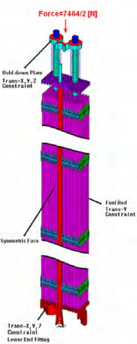
The finite element model must be accurately created as a pre-described joint/connection configuration. Only a centre guide tube was modelled as a contact surface definition between two parts because it was placed on the bottom nozzle. However, the joints between the guide tubes and the top/bottom nozzles were made with a thread joint. And these joints between the spacer grids and the outer guide tubes had a welding joint condition. Therefore, these joint parts were modelled with a one body to secure a rigid body motion [5]. However, the connections between the fuel rods and the grid supports revealed friction phenomena due to an insertion of the fuel rods. So it was necessary to perform a non-linear contact analysis between them. Because of these initial interferences they create a little higher stiffness of a global structure than that of just a contact case. The total number of nodes and elements were 340,126 and 274,811, respectively. And the global finite element model is shown in Fig. 2.
4
Figure 3: Applied boundary conditions of a quarter scaled fuel assembly for a drop analysis.
Analysis Procedure
The finite element analyses were divided into two steps, one was the non-linear contact analysis, and the other was the axial free fall impact analysis. Of course, the initial state of the second step was the actual state from the first step analysis result. The total computational time was defined as 0.24 sec. for the secondary impact simulation. The software and hardware for the analyses are summarized in Table 3. A secondary impact peak occurred at the top surface of the base plate. The restitution factor due to a repeated behaviour was determined by using this rebound displacement of the fuel assembly.
Table 3: Software & Hardware information for a drop analysis
S/W H/W
Non-linear Drop impact
ANSYS Ver. 10.0
LS-DYNA3D Ver. 960
Windows XP 64 bit Dual AMD Opteron 275
4GB Main memory Quadro FX4400 VGA
AXIAL IMPACT ANALYSIS RESULTS AND DISCUSSION
Non-linear Contact Behavior Between a Fuel Rod and Grid Supports
When the fuel rods were inserted into the inner cell of the grids, the fuel rod support parts, grid spring and dimple, experienced a deformation and stress due to these insertions. These pre-stresses brought about an increase in the stiffness of the grid structure and the global stiffness of the whole structure was also increased.
On the other hand, for the fuel rods modelled with a cylindrical shape; they excite the number of nodes and elements too much. This analysis model might not be converged with a much larger problem size. Therefore a model of the fuel rods was created with an octagonal shape. The contact surfaces between the surface of the fuel rods and the supports of each grid part were defined, and then the first analysis step was solved for a non-linear contact problem. So these initial interference parts were eliminated and thus it increased the stiffness of the whole model. At this time, the stresses of the grid dimples were much lower than those of the grid spring. Because, the stiffness of a grid dimple showed a much higher value than that of a grid spring.
The stress configuration of an inner grid cell is shown in Fig. 4. In this figure, the global stress levels were distinguished as two parts, i.e. grid spring and a spring from the non-linear contact analysis. The current state of the structure was the initial condition for implemented the dynamic impact analysis, so it was imported as the initial state for DYNA3D.
(a) before (b) after
Figure 4: Pre-stress configuration from the non-linear contact analysis.
Impact Behavior of a Fuel Assembly Structure
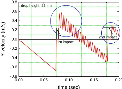
The velocity history of the centre node of the bottom nozzle at the 25 mm drop height is shown in Fig. 5. In this figure, the velocity characteristic curve after the first impact had an unstable behaviour. This unstable behaviour was caused by a slip motion between the joint and connection parts. These relative movements affected the axial impact analysis results.
0.00 0.05 0.10 0.15 0.20
-0.8 -0.6 -0.4 -0.2 0.0 0.2 0.4 0.6 0.8
Y-velo
city (m
/s)
time (sec)
1st impact
6
The primary impact velocity was 0.691 m/s from this analysis. In the actual impact test, an impact load showed several times during the free fall event. However, the impact simulation revealed a little difference in the resultant phenomena because of a non-similarity between the actual structure and analysis model.
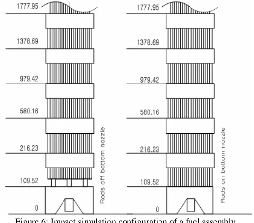
On the other hand, the impact behaviour of the whole model differed from the rods on the bottom nozzle case and the rods off the bottom nozzle case as shown in Fig. 6.
Figure 6: Impact simulation configuration of a fuel assembly.
The impact force history of the 16 by 16 type fuel assembly is shown in Fig. 7. The first and second duration times were 0.006 seconds and about 0.008 seconds, respectively. The first maximum impact force was approximately 111.5 kN, and the second one was 57.6 kN. These values revealed a little discrepancy from the previous experimental results. However, the simulation results showed a similar trend to the experimental results.
0.00 0.05 0.10 0.15 0.20
0 30 60 90 120
Impa
c
t F
o
rc
e (k
N)
time (sec)
drop height = 25mm
Figure 7: Impact force history of a center node of the bottom rigid surface at a 25mm drop height.
0
0
h
h
v
v
e
=
=
(1)where
v
=
2
g
h
is the velocity after a collision,v
0=
2
g
h
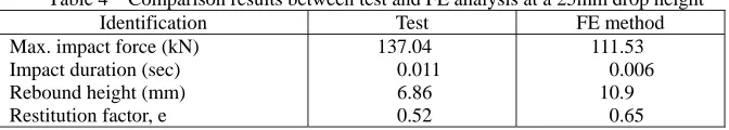
0 is that of it before a collision. And therebound height, h0 is the initial height. The rebound height at the 25 mm drop height was 10.9 mm, so the restitution factor was 0.65, which is very close to the value of the previous result.
The analysis results are summarized in Table 4. Of course, the maximum impact forces revealed a little difference from the previous test results. However, the model for the analysis was not exactly the same as the test specimen. In addition, the joint and connection parts of the structural components also had a disparity from the actual specimen. Although, the finite element model had the above discrepancies, the analysis results showed reasonable results when compared with the previous experimental results.
0.00 0.05 0.10 0.15 0.20
-30 -20 -10 0
δ (
mm
)
time (sec)
drop height=25mm
1st impact 2nd impact
Figure 8: Displacement history of a center node during a free-fall impact.
Table 4 Comparison results between test and FE analysis at a 25mm drop height
Identification Test FE method
Max. impact force (kN) Impact duration (sec) Rebound height (mm) Restitution factor, e
137.04 0.011 6.86 0.52
111.53 0.006 10.9
0.65
CONCLUSIONS
8
ACKNOWLEDGEMENTS
This project has been carried out under the Nuclear R&D Program by MOST.
REFERENCES
1 H. N. Rhee Fuel Assembly Mechanical Design Manual, KNU-FMDE-DM01, Rev.00, KAERI. 1989. 2 H. N. Rhee Fuel Assembly Mechanical Design Report, KNU-FMDE-DR01, Rev.00, KAERI, 1992.
3 ANSYS Ver. 9.0 User’s Manual, ANSYS, Inc., 2004.
4 LS-DYNA3D Ver. 960 User’s Manual, LSTC, 2004.
5 K. H. Yoon et. al., “Non-linear Dynamic Buckling Analysis of a Grid Structure”, Key Engineering Materials, Vol. 183-187, pp. 451-456. 2000.
6 K. H. Yoon et. al., “Drop Impact Analysis of a Fuel Assembly for PWR by FE Method”, Proceedings of the KSME