AN EFFICIENT SOLUTION A L G O R I T H M FOR FAST TRANSIENT FLUID
STRUCTURE INTERACTION ANALYSIS WITH TWO PHASE FLUID ELEMENT
IN AN ALE CODE
P.Chellapandi, S.C.Chetal and S B Bhoje
Indira Gandhi Centre for Atomic Research, Kalpakkam-603 102, India A B S T R A C T
In order to predict the complex core bubble movements within the fast reactor assembly containing sodium, argon, reactor internals under a core disruptive accident (CDA), a two phase fluid element is developed and implemented in the ALE code 'FUSTIN'. The effectiveness of the element behaviour is demonstrated by solving 3 benchmark problems of direct relevance to FBR safety analysis. With this element, it is possible to predict satisfactorily the hydrodynamic and structural responses over the entire transient period.
INTRODUCTION
Fast Breeder Reactor (FBR) has many inherent and engineered safety features that a core disruptive accident (CDA) which involves melting of whole core, is of very low probability event (probability of occurrence is less than 10-6). Hence CDA is categorised as a beyond design basis event (BDBE) for 500 MWe Prototype Fast Breeder Reactor (PFBR). However, following the philosophy of defense-in-depth, it is analysed in detail to respect the specified safety criteria [ 1 ]. In the analysis, failure of all the reactor core protective systems is hypothetically postulated and the reactor attains super prompt critical condition. During this period, there is an unbalance between heat generation in the core and heat removal by the coolant leading to melting of core. This, ultimately creates a highly pressurised liquid-vapour mixture, called "core bubble', at the core centre. Not in equilibrium with the surrounding sodium, the core bubble expands rapidly generating shock/pressure waves which, intum produce large plastic deformations on the surrounding vessels. Further, due to the presence of cover gas space available above the sodium free level, the portion of the sodium above the bubble is accelerated upwards, which subsequently causes an impact on the top shield, called 'sodium slug impact'. Due to this slug impact, apart from the possibly large stresses developed on main vessel in the vicinity of the roof slab junction, a fraction of sodium is ejected through the top shield penetrations to Reactor Containment Building (RCB). The consequent sodium fire results in an increase of pressure and temperature which may pose threat on the structural integrity of RCB, the ultimate barrier of reactivity release.
Classically the structural integrity of primary containment vessel under CDA is demonstrated through tests on scaled down models filled with water detonated using low density chemical explosives. With advances in the computational capabilities, detailed theoretical analysis involving features which can simulate all the essential aspects of the accident is followed in the recent years to demonstrate the safety of the reactor under CDA. Theoretical analysis calls for sophisticated mathematical modelling for the treatment of large displacements of fluid and structure, shock waves, fast transient fluid-structure interactions and complex movements of core bubble with the presence of above core structures. In the hydrodynamic computations, there exists significant non-linearities, basically due to high fluid velocities, large motions of free surfaces and fluid-structure interactions; the type of mesh description is an important aspect to be considered. There are three basic mesh descriptions, viz. Lagrangian, Eulerian and Arbitrary Lagrangian - Eulerian (ALE). If the nodal co-ordinates are fixed in space, the mesh is Eulerian; if the nodes are fixed to the material points and move with the computational mesh, it is Lagrangian. In the ALE, the mesh can be specified to move independent of the material.
Lagrangian meshes suffer from distortion if large motions of the fluid take place. Hence their analyses are limited to the early stages of the excursion. These can be corrected by rezoning during computation, but rezones introduce errors into momentum and energy-balance. Even with rezones, a Lagrangian procedure can not satisfactorily treat flow around corners. However, the Lagrangian mesh has the advantage that boundaries of the fluid and fluid structure interfaces remain on the boundaries and interfaces of the mesh. So they are easily dealt in.
Eulerian meshes are well suited to the treatment of large flows and flows around corners. Because nodes are fixed in space, there is no possibility of mesh distortion. However, when the motions of interfaces or boundaries are large, the coupling of Eulerian mesh with a structure is quite complicated. The boundary or interface may pass through the middle of an Eulerian zone or it may cut across comer.
In the ALE formulation, the meshes are allowed to move independent of the material. In these methods the nodes adjacent to a structure or on a boundary/interface can be moved in Lagrangian way so that the difficulties associated with Eulerian formulations are avoided. On the other hand, the mesh interior to the fluid can be treated in an almost Eulerian fashion so that the mesh distortion associated with Lagrangian codes is avoided. The practical implementation of the ALE description requires an automatic mesh displacement prescription algorithm. In the two-dimensional ALE finite-element computer code FUSTIN developed for the structural integrity assessment of primary containment of FBR under CDA [2], a rezoning algorithm originally developed by JRC-ISPR [3], is implemented. By this algorithm, it is not possible to handle the situation when one interface
SMiRT 16, Washington DC, August 2001
Paper # 1405intersects the another interface, for example, the core bubble boundary intersects the surrounding structural boundaries. This situation is inevitable when it is required to analyse for the entire transient behaviour which may last typically about 300 ms. Hence, more powerful techniques are to be implemented in the computer code to handle such situations. Two of the methods used to treat such situations are the marker-and-cell methods, which combines an Eulerian cell structure with Lagrangian markers [4] and volume of-fluid-methods [5] in which a scalar variable in each cell is used to track the passage of surfaces through a Eulerian cell structure. The treatment of all these complex phenomenon requires considerable programing efforts. Further making the program applicable for any arbitrary structures is difficult. To overcome these difficulties, a homogeneous fluid element consisting of liquid or its vapour in association With a gas has been developed based on a technique used in ref [6]. This paper deals with derivation of equation of state for the homogeneous fluid element and method of solution. The effectiveness of the homogeneous element is demonstrated by solving 3 benchmark problems relevant to FBR safety analysis. H O M O G E N E O U S F L U I D E L E M E N T C O N C E P T
In a typical homogeneous fluid element, both liquid or its vapour and gas phases can co-exist. It is assumed that each phase keeps its behaviour law (equation of state) unchanged within the element. Heat transfer between the phases is neglected and the two phases are assumed to be immiscible. In an homogeneous element which has net mass M, volume V and internal energy I, the liquid mass fraction is [3 and liquid volume fraction is ~. [3 is known. The associated mass and volume fractions for gaseous phase are (1- 13) and (1- c~). Since the pressure (P) is uniform in the element, the internal energies stored in liquid and gas phases are proportional to the corresponding volume fractions, i.e. c~.I and (1-c~).I respectively. P depends upon c~ value.
In the homogeneous fluid, the identification of exact liquid and gas interface is naturally lost. However, due to a large difference in the density values of liquid and gaseous phases, the graphical display of isovalue density contours depicts the interface in a narrow band.
E Q U A T I O N OF S T A T E F O R H O M O G E N E O U S F L U I D
In the ALE finite element code, the density, specific internal energy and pressure are the elemental properties which are derived from the nodal velocity vectors. The pressure in the element is defined by the equation of state (EOS) of the fluid. The objective here is to determine the equilibrium pressure (P) in a typical fluid finite element consisting of liquid or its vapour and gas. The known quantities are the net element mass M, liquid mass [3.M, gas mass (1-[3).M, specific internal energy i and volume V. EOS for liquid and gas are defined by functions: PI = fl (Pl, il) and Pg = fg (pg, ig) respectively. The density of liquid and gas phases are computed from corresponding mass and volume" Ol = ml / Vl = [3/~. R and pg = (1-[3)/(1-c~).R, where R is net density of the element (= M/V). The specific internal energy, i.e. internal energy per unit mass is derived as: il = (~/[3).i and (ig) = (l-m)/(1- [3).i respectively for liquid and gaseous phases, where, i represents the net specific internal energy for the element (= I / M). Since ~ and P are inter-dependent, once ~ is known, P can be computed.
In order to determine ~, the following mechanical equilibrium equation under quasi-static condition is used.
P = Pl = Pg if P1 > P s a t (1)
If liquid pressure Pl is less than vapour pressure esat, it vapourises and subsequently pressure remains as Psat. It occupies the entire volume of the element as that of the gas. Under this condition,
P = Psat + Pgmin (2)
w h e r e Pgmin is the gas pressure when it occupies the entire element volume.
Pseudo Viscous Pressure in the Homogeneous Fluid
In order to avoid the possible numerical problems due to shock wave propagation, an artificial damping is introduced in the form of pseudo viscous pressure (q) which is added to P [7]. This makes a smooth velocity gradient across the element.
q = R [a.A. (div. V) 2 - b.~/(div V)] if div.V < 0 (3)
= 0 if div.V > 0
where a and b are constants associated with the quadratic and linear terms. A is elemental area. The div.V is given by:
div.V = c~ (Ap/p)l + (1-c~) (Ap/p)g (4)
Sonic Velocity in the Homogeneous Fluid
The minimum time step required for the stable solution depends upon the sonic velocity 'c' in the homogeneous element, which is determined from the sonic velocities in liquid and gaseous phases (Cl and Cg respectively), using the equation:
S O L U T I O N T E C H N I Q U E
In the FUSTIN Code, numerical time integration of the semi-discrete conservation equations of mass, momentum and internal energy is done in 2 stages. The first stage is an explicit Lagrangian phase in which convective contributions are ignored and the second stage which takes into account the convective contributions is also explicit. In stage II, the volumes, masses and internal energy values that are associated with the individual phases in the elements are updated. Accordingly the elemental pressure P, is to be computed. In this section the method of determining P in a typical homogeneous fluid is explained.
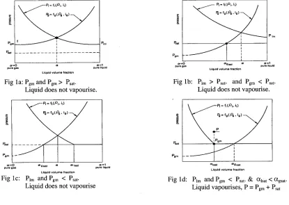
For determining P, the resulting transcendental equation (1) has to be solved which has only one unknown o~. This is solved using Newton Raphson method. If solution is not converging in case of zero slope, a simple bisection method is employed. If 13 < 10 .8 or o~ < 10 -~°, liquid phase is ignored and EOS for pure gas is used to determine the elemental pressure. If~ > (1-10 8 ) or o~ > (1-10-10), gas phase is ignored and EOS for pure liquid is used to determine the elemental pressure. These limits have been arrived at to avoid numerical problems. For 10 -8 < 13 < (1-10 -8 ) and 10-~0 < o~ < (1-10-~0 ), solution is sought for the following 4 possible situations which are illustrated graphically in fig 1. In these graphs, Pgm is the minimum pressure possible for the gas if it alone occupies the entire element volume and Plm is the minimum pressure possible for the liquid if it alone occupies the entire volume. If Plm is less then Psat, liquid vapurises and hence, Plm = Psat. O~gsat is ~ at which Pg = Psat. and O~lsat is c~ at which Pl = Psat.
egrn
Psat
Plm ~.t
a---O a = l
pure gas pure liquid
Liquid v o l u m e fraction
Fig l a: Pgm and Pgm > Psat. Liquid does not vapourise.
Pgm " a--'O
pure gas
P Im
a g sat a ol = 1 pure liquid Liquid v o l u m e fraction
Fig lb: Plm > Psat. and Pgm < Psat. Liquid does not vapourise.
~
1 - - P i = f , ( P l , i l ) /=
i
o .
Psat
Pom ""
a = O a gsat ix of Isat pure gas
Liquid v o l u m e fraction
Fig l c" Plm and Pgm < Psat. Liquid does not vapourise
a = l pure liquid
Psat
P0m
\ / P ' ;
f'(P"")
/
oqsat a g sat Liquid v o l u m e fraction
Fig ld" Plm and Pgm < Psat. & C~lsat < (~gsat. Liquid vapourises, P = Pgm -I- Psat
S O L U T I O N OF B E N C H M A R K P R O B L E M S M E N O N Test [ 8]
A flexible cylindrical shell with rigid covers both at top and bottom and completely filled with water, is subjected to low density explosion at its centre. Fig 2a provides geometrical details and fig 2b depicts the stress strain curve.
/
//-- Rigid top & bottom
. . . .
¢ 3 8 0 m m
Fig 2a. Geometrical details
--- Test vessel (1.2mm Thk) Water (completely filled) Pentolite (at centre)
O ' ( M P a ) 6 0 0 5 5 9
4 8 1 - - - - - -
352 I ~
2 6 5
Ill i I
oll i --J--
0 . 1 3 9 2 . 0 2 10.5
RT
C (%)
EOS for core [8] " P = Po (P/Po) 1"535 where Po = 288 MPa and Po = 482 kg/m 3 (6)
EOS for water [9] : P = 1.0xl05 P1.P2 + 0.28.p.i/V (MPa) (7)
V = 9o/9; P~ = 0.1483 P3 +2.086P32-1.398 P33 ;
P2 = 1 - 0.14(1-V)/V ; P3 = [Z +Z 2 +0.8293(1-V) 2] / [2.796(1-V)] Z = 2.086(1-V) - 1; P3 = 0 if V =1; Po = 1000 Kg/m 3 & io = 0 MJ/kg
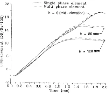
Considering the symmetricity, only 1/4 of the geometry is modelled. The analysis is done up to 2 ms using both single phase and two phase elements. Fig 3 depicts the mesh configurations at 3 discrete time intervals. This figure clearly shows that the prediction of expansion of core bubble by two phase element is very close with the corresponding results predicted by the single phase model. In fig 4, the evolution of kinetic and vessel strain energy values is compared.
Single phase model
Oms 1ms 2 ms.
Tw o phase model
Fig 3. Original and deformed mesh configurations
Single phase elemenL
2 0 ] Mul[i phase elemenL , ~ . - - - .---1
t
- /
train energy
16-
~ 8
4
J / ~,~ Kinetic energy
0 . 0 O . B 0 . 4 0 . 6 O . B 1.13 1 . 2 1 . 4 1.13 1 . B 2.0 Time ( m s )
Fig 4. Energy balance
In fig 5, the prediction of vessel strains at 3 elevations is compared. Fig 6 shows the comparison of predicted vessel strain at the mid point with the test data. The results demonstrate that the performance of two phase element is excellent.
o
o
1(1 7)
0E~ 6-
k
.,_~ oil
2 2 - - . . . S i n g l e p h a s e e l e m e u L
. . . Multi p h a s e e l e i n e n f i
=.
~ / ~ Y
=--~,_o == /
._
l"---r--- I - - r - 0 0 0.2 0.4 0.6 0./:] 1.0 1.2 1 4 1.~ 1.B 2.0
T i l i l e ( I ' I l S )
Fig 5. V e s s e l strains at 3 locations
2 2 -
1_4- .._1
i
~JI
(].C) 0.2 0.4 (),6 0,I 1.0 1.2 1.4 t.6 I.B 2.0
T i m e (ms)
I . . . F U S T I N (single phase element.)
t . . . F U S T 1 N 0 n t ] l t , i phase elemenfl)
-~ . . . P L I ! J X ( J S
4 ... M E N O N L e s t (C]IA) zl" ~ . ,
-~.,
Fig 6. Vessel strain at mid-elevation
C O V A Test [9]
i
Rigid c o v e r 3 . ~Air ~ ~ " ~
_~ I . . . . I - - - . I ~,,~o~ve ~ ,.5=
~ Thln vesseZ
, I
Fig 7a. Geometrical details
.... t , • , , i , , , , , . • - , ...
Ois~Qnce (cM) (,1o 1)
Fig 7b. Vessel thickness
0 (MPa)
I / ~=°~333 3
275 ~ 5 5 ,0 - 7900 kg/m
Fig 7c. Stress strain curve
The EOS for water, equation (7) used for the MENON test is also used here. For the explosive charge, the following expression is used as per the reference [9].
P = 17039[ 1-0.0111/V]e 9v+ 1159.5 [ 1-0.0417/V]e2"4v+(0.19oi- 102.9)/V (MPa) where V =
9o/P
; 19o = 1000 kg/m 3 and io = 1.629 (MJ/kg).The finite element mesh consists of 607 four-noded fluid elements for modelling water and explosive and 26 two-noded shell elements. The nodes on the water free surface have been
taken as purely Lagrangian. The rest of the domain has been moved automatically by the computer program. The air gap above the water free surface is treated as void. Computations are carried out upto 4 ms. Fig 8 shows the original and deformed configurations of the mesh at times 1, 2, 3 and 4 ms for the computations by single phase and two phase elements. The important increase of the charge volume, the progressive impact of water on the top cover and the successive deformation of the vessel particularly at the location just below the top cover are clearly seen on the figures. Further, the figures also show that the automatic mesh displacement algorithm has performed quite well.
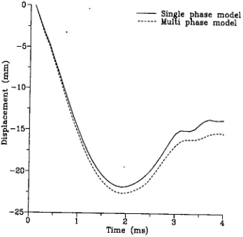
The displacement of the bottom most point of the dished end and the meridional profile of the hoop strains are compared in figs 9-10 respectively. A fairly good agreement between the two computations may be noted.
Single phase model
oms 1ms 2ms 3ms
Two phase model
Fig 8. Original and deformed configurations
4 m s
- 5 ¸
.~, - 1 0 .
o =
~ - 1 5 -
. , ' 4 C ~
- 2 0 .
- 2 5 0
" S i n g l e p h a s e m o d e l
. . . ' d e l
T i m e ( m s )
Single phase model ... Multi phase model
10
.'k
~ 4
C O
i
CONT Benchmark Problem [10]
A simplified pool type FBR geometry consisting of a cylindrical vessel with a hemispherical bottom dished end is solved. The reactor roof is represented by a rigid plate fixed to the ground and the
top part of the reactor vessel is clamped to the roof. Vessel is filled with sodium with a cover gas space of l m at the top. In order to study the effects of the internal structures, a stainless steel cylindrical inner tank is included surrounding the core region. The thickness for reactor vessel as well as for inner vessel is 25 mm. Three fluids, sodium, argon cover gas and core bubble are present within the reactor vessel. The geometrical details are given in fig 11.
The core bubble polytropic type equation of state is considered as an approximate representation of a hypothetical CDA characterized by an energy release of 600 MJ during the core bubble expansion from an initial pressure of 10 MPa to a final reference pressure of 0.1 MPa. Accordingly, EOS for core bubble is written as:
EOS for core bubble: P = Po(Vo/V) °'75 where Po = 10 MPa, Vo = 4.119 m 3 and V is current volume in m 3" P = Po
[(Wo/V) 1"67-1] where
P o - 0.1 MPa, Vo = 314.16 m 3 and V is current volume in m 3. EOS for cover gas •Boundary condilions: hinged
R e a c l o r __.-> °" vessel
, /
Inner / /
vessel
Hold down boils Rigid roo!
Fig 11. Geometrical details
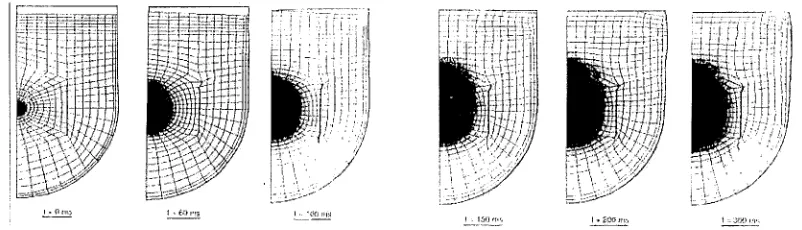
EOS for sodium • P = 4.44x10³# + 4.328x10⁹/z //z / + i (1.218 + 1.218#) MPa, where /.t = (P/Po -1), Po = 832 kg/m 3 The stress strain curve for the stainless steel of the inner tank and primary vessel is represented by a constitutive law and material parameters shown in fig 12. The finite element mesh consists of 546 four-noded fluid elements and 34 two-noded shell elements. Cover gas space is modeled as a single homogeneous zone with the nodes on the sodium free surface as Lagrangian. First analysis is done with single phase elements treating the core bubble boundary as Lagrangian. Due to presence of inner vessel, the core bubble boundary movements became very complicated and hence the rezone algorithm failed after the computations up to 150 ms. The original and deformed mesh configurations up to this time interval are shown in fig 13.
O" (MPa)
i 1,
i
-- --2-£-~
O r e s
~-iI
i
80 ms
1 0 5
I / / . / = 0 . 3 3 3 3
[/~
E = 1.6 x 1 1 I(MPa) 150msFig 12. Stress strain curve Fig 13. Mesh configurations predicted by 'single element'
Using 'two phase fluid element', analysis has been carded out up to 300 ms. The mesh configurations at 6 discrete time intervals are shown in fig 14. This clearly shows that, with the application of 'two phase element', it is possible to predict the hydrodynamics involving very complicated core boundary movements over the long duration.
~:,~.-: -.-- ... ~ ... ~,-~ ~ ~, ,[ fif ~ i ~ ~ ! ~ i i ~ ~-~:~ =~':~:i~:~:~-~!~t ~ ~ ~:i~i'l
. , /
•
Some important results obtained using FUSTIN code are compared with the predictions by other international codes, viz. SEURBNUK (UK), EURDYN (JRC), PISCES (USA), ASTARTE (UKAEA: ENEA-BOLOGNA), SIRIUS (France) and CASSIOPEE (CEA: ENEA-BOLOGNA). The parameters compared are: strain energy in the reactor vessel (fig 15), hoop strain profile along the vessel at the end of 300 ms (fig 16), the pull-down load offered by the reactor vessel at the support (fig 17), the pressure rise in the cover gas space (fig 18), pressure at the roof bottom at 2 locations (fig 19) and the impulse at the bottom centre point of top shield (fig 20). All these figures clearly demonstrate that the 'two phase fluid element' performs fairly well even for the solution of complex practical problem which has to be considered as a satisfactory achievement.
a SEURBNUK UK
Energy (MJ) • S E U R B N U K JRC S E U R B N U K / E L J R D Y N j ? C ; ~ISCE=J
300] 0 AS I'ARTE E NEA
! O SIRIUS CEA
0 2'0 40 60 80 100 120 140 160 180 200 220 240 260 Time (ms)
Final hoop strains ( % )
SEIJR[3rqU K UK A)
4 J • S E ~ R B N U K J R C
| x S E { J R ~ N U K / E U R D Y N JRC | I P I S C E S P!
I o ASTARTE ENEA ~
3 i o SiRius CEA: ..-_ /
J • CASSIOrJE E Ef~EA / ~ I ~ 4 ~
o
0 4 - - ~ o - __ , ~ , , ,
0 5 10 15 20 25 27
Distance (m) Fig 15. Strain energy in the vessel Fig 16. Hoop strain profile
t,oad (MN)
~ 0 0 ]
450- 400, 350.
300 ~
2 5 0 . 2 0 0 - 1 5 0 . 1 0 0 -
5o~
0 - - 5 0 -
0 20 40 60 80 100 120 140 160 180 200 220 240 260 Time (roll)
~ SEU!RBNUK UK S E U f ~ B N U ~ JRC x S E U R B N U K / E U R E } Y N JR(;
• ~ISCE5 Pl
{3 ASTARTE ENEA
O SIRIUS CEA
• CASSIOPEE F_ ~I EA
-- FUSTIN ! I~oli\
x
Fig 17. Roof pull-down load on main vessel
6 -
Pressure (MPe) 3.0- 2.5- 2.0" 1.5- 1.0- o.5-
~ SEIJRBNtJI< u K S E u R B N U K JRC x S E u R ~ N U K / E I J R O Y N JRC
~ PISCES Pl
ASTARTE ENEA
SIRIUS CEA
• CASSIODEE E~JEA
'* ,~TI t IA
. . . ~ ~"~
o 20 40 60 80 loo 12o ~ o 1~o 18o 200 2~o 2~o 2~o
Time (ms)
Fig 18. Cover gas pressure
5 -
. . - . 4 -
2
0 - o
At centre
. . . A T I H X / P u m p PCD
/
so loo 15o 260 2~o 3~o
T i m e ( m s )
Fig 19. Impact pressure
'repulse (KPa.s):
300-
:LP../0 •
150"
100"
; SELIRI~NUK UK
S E U R B N U ~ dRC
; S E U R I 3 N U D ' / E u R D Y N J R C
PISCES p l
~ ASTAR't E E N E A
SIRIUS CEA
at C A S S I O P E E ENEA
FUSTIN INDIA
/j;f:f~
o 20 40 e3 8~) 16o lio 1~o 1~o 18o 200 220 240 2~o
CONCLUSION
In order to predict the complex core bubble movements within the fast reactor assembly containing sodium, argon, reactor internals under a core disruptive accident, a concept of two phase fluid element is developed and implemented in the ALE code 'FUSTIN'. The pressure in the homogenous fluid element is solved efficiently. 3 benchmark problems of direct relevance to FBR safety analysis are solved using both single phase and two phase elements with the automatic rezone algorithm. The results have demonstrated satisfactory performance of two phase fluid element for the MENON and COVA test problems. 'CONT', an international benchmark problem could not be solved beyond 150 ms with 'single element' due to the inability of the rezone algorithm when the core bubble boundary undergoes very complicated path with the presence of an internal structure. However, the same has been successfully solved using 'two phase fluid element' over sufficiently a long time (upto 300 ms).
With the two phase fluid implemented in the ALE code 'FUSTIN', it is possible to predict satisfactorily the hydrodynamic behaviour of core bubble and sodium with the presence of control plug, disintegration of core bubble and sodium spillage through top shield taking into account the effects of cavitations on the wave propagation in the liquid sodium, till the end of transient phase during CDA in an FBR.
REFERENCES
10.
S B Bhoje, 'Safety Criteria for PFBR', AERB Document, April 1987.
Chellapandi,P., 'Treatment of Fluid Structure Interaction with FUSTIN Code', Proc. Int. Con. Finite Elements in Computational Mechanics (FEICOM-85), IIT Bombay, 2-6 Dec 1985. pp. 743-752.
S.Giuliani, "An Algorithm for Continuous Rezoning of the Hydrodynamic Grid in Arbitrary Lagrangian-Eulerian Computer Codes' Nuclear Engineering and Design 72, North-Holland Publishing Company, 1982, pp 205-212. J.E.Welch, F.H.Harlow, J.P.Shannon and B.J.Daly, "The MAC Method: A Computing Technique for Solving Viscous, Incompressible, Transient Fluid-Flow Problem Involving Free Surfaces', USAEC Report LA-3425, Los Alamos Scientific Laboratory, NTIS, March 1966.
C.W.Hirt and B.D.Nichols, 'Volume of Fluid (VOF) Method for the Dynamics of Free Boundaries', J.Computational Physics, 39:201-225, 1981.
M.Lepareux, H.Bung, A.Combescure, J.Aguilar, "Analysis of a CDA in a LMFBR with a Multiphasic and Multi - components Behaviour Law' Trans. 1 lth Int. Conf. Structural Mechanics in Reactor Technology, Volume E: Fast Reactor Core and Coolant circuit Structures, Tokyo, Japan, Aug 1991, pp 371-376.
J.Donea, P.Fasoli-Stella, S.Giuliani, J.P.Halleux, and A.V.Jones, The Computer Code EURDYN-1M for Transient Dynamic Fluid-Structure Interaction, Part-1: Governing Equations and Finite Element Modelling' Commission of the European Communities Nuclear Science and Technology, Report EUR 6751 EN, 1980.
M.Lepareux, B.Schwab, H.Bung (CISI), 'PLEXUS, Validation de la methode ALE, Interpretation de l'essai MANON 11', CEADEMT RAPPORT 84/246 (SMTS/LAMS/84-115), 1984, pp 1-39.
J.Donea, S.Giuliani,'An Explicit ALE Finite Element Formulation for 3D Transient Dynamic Fluid-Structure Interaction Problems' Commission of the European Communities Nuclear Science and Technology, Report EUR 11936 EN, 1989, pp 1-56.