ABSTRACT
CHOI, INCHUL. A Sensorimotor Rhythm (SMR)-Based Brain-Computer Interface (BCI) Controlled Functional Electrical Stimulation (FES) for Restoration of Hand Grasping and Extension Functions. (Under the direction of Dr. Chang S. Nam.)
Each year, 795,000 stroke patients suffer a new or recurrent stroke and 235,000 severe Traumatic Brain Injuries (TBIs) occur in the US. These patients are susceptible to a combination of significant motor, sensory, and cognitive deficits, and it becomes difficult or impossible for them to perform activities of daily living due to residual functional impairments. Recently, Sensorimotor Rhythm (SMR)-based Brain-Computer Interface (BCI) controlled Functional Electrical Stimulation (FES) has been studied for restoration and rehabilitation of motor deficits. However, there are some central issues in current studies as follows: Unclear guidelines to identify adequate FES electrode placement and parameters; unstructured Motor Imagery (MI) training procedures; lack of studies to classify different MI tasks in a single hand, such as grasping and opening; and difficulty in decoding voluntary MI-evoked SMRs (voluntary) compared to FES-driven passive-movement-evoked SMRs (passive).
This research tried to address these issues by proposing a novel SMR-based BCI-controlled FES system with 2-class MI tasks in a single hand, and investigated the feasibility of the proposed system with stroke and TBI patients.
to identify user-specific FES parameters. The post-hoc analysis revealed the scores of some FES parameters were significantly lower than that of the fixed parameters (pulse rate = 35 Hz; pulse width = 220 μs). It implied that the application of the user-specific FES parameters can decrease perceived muscle pain and discomfort, and, consequently, help to increase user satisfaction.
The objective of Study 2 was to propose a novel SMR-based BCI with visual guidance for (1) classifying 2-class MI tasks; (2) distinguishing voluntary and passive SMRs; and (3) identifying the best classification method. Participants were asked to mentally mimic visual guidance representing two different rhythmic MIs in synchronous experiments. The results showed that the accuracy of classifying 2-class MIs (~71.25%) was significantly higher than the true chance level, while that of distinguishing voluntary and passive SMRs was not. Furthermore, the standardized accuracies between three classification methods were significantly different, and the ensemble method showed significantly higher accuracy than linear discriminant analysis.
increased, while performance significantly decreased during semi-asynchronous experiment compared to synchronous experiment.
A Sensorimotor Rhythm (SMR)-Based Brain-Computer Interface (BCI) Controlled Functional Electrical Stimulation (FES) for
Restoration of Hand Grasping and Extension Functions
by Inchul Choi
A dissertation proposal submitted to the Graduate Faculty of North Carolina State University
in partial fulfillment of the requirements for the degree of
Doctor of Philosophy Industrial Engineering Raleigh, North Carolina
2017
APPROVED BY:
________________________________ ______________________________
Chang S. Nam David A. Dickey Committee Chair Minor Member
_____________________________ ______________________________
David B. Kaber Dean J. Krusienski
_____________________________
ii
DEDICATION
I dedicate my dissertation to my wife, Soyoung Kim, and lovely daughter, Hana, whose boundless support, patience, and encouragement helped me throughout my studies. I am truly thankful to have you in my life.
iii
BIOGRAPHY
iv
ACKNOWLEDGEMENTS
v
TABLE OF CONTENTS
ABSTRACT ... i
TABLE OF CONTENTS ... v
LIST OF FIGURES ... x
LIST OF TABLES ... xiii
LIST OF CONTRIBUTING PUBLICATIONS ... xvi
LIST OF ACRONYMS ... xvii
LIST OF ACRONYMS FOR BONE AND MUSCLE ... xix
Introduction ... 1
How does FES work? ... 6
1.1.1. Stroke and Traumatic Brain Injury ... 6
1.1.2. FES Rehabilitation for Stroke and TBI Patients ... 7
1.1.3. Limitations of Current FES Studies ... 9
How does SMR-based BCI-controlled FES work? ... 11
1.2.1. What is a BCI? ... 11
1.2.2. SMR-based BCI-controlled FES Systems ... 13
1.2.3. Limitations of Current SMR-based BCIs for FES Studies ... 15
The Objectives of Research ... 17
Literature review and survey ... 18
FES System Survey ... 18
2.1.1. FES Principles ... 19
vi
2.1.3. Principal Muscles for Hand and Wrist Motions ... 22
2.1.4. Features in FES Operation ... 26
2.1.5. Summary ... 32
Review on FES Systems for SMR-based BCI ... 34
2.2.1. Systematic Review Procedure ... 34
2.2.2. FES Systems in Current Research ... 35
2.2.3. FES Electrode Placement and Parameters in Current Research ... 38
2.2.4. Limitations of Current Research ... 44
Review on SMR-based BCIs for FES ... 46
2.3.1. Systematic Review Procedure ... 46
2.3.2. MI Instruction and Tasks in Current Research ... 48
2.3.3. Signal Processing for SMR-based BCIs ... 53
2.3.4. Limitations of Current Research ... 65
Research Questions and Hypotheses ... 66
2.4.1. Hypothesis in Study 1 ... 66
2.4.2. Hypotheses in Study 2 ... 67
2.4.3. Hypotheses in Study 3 ... 69
Study 1: Development of An FES Platform ... 70
Phase 1: Development of an FES System ... 72
3.1.1. Objectives ... 72
3.1.2. Characteristics of TENS 3000 ... 72
3.1.3. Modification of TENS 3000... 76
3.1.4. Results ... 78
vii
3.2.1. Objectives ... 81
3.2.2. Participants ... 82
3.2.3. Preparations ... 84
3.2.4. Apparatus ... 85
3.2.5. Procedures ... 85
3.2.6. Independent and Dependent Variables ... 89
3.2.7. Experiment Design and Statistical Analysis ... 90
3.2.8. Results ... 92
Discussion... 102
Study 2: Development of a Novel SMR-based BCI System ... 105
Objectives... 105
Methods ... 106
4.2.1. Participants ... 106
4.2.2. Visual Guideline ... 106
Procedures ... 107
Signal Processing ... 111
4.4.1. Signal Acquisition ... 111
4.4.2. Signal Preprocessing ... 113
4.4.3. Feature Extraction ... 119
4.4.4. Classification ... 120
Independent Variables ... 122
Dependent Variables ... 122
4.6.1. Brain Activity ... 123
viii
4.6.3. Subjective Assessment ... 123
Experiment Design and Statistical Analysis ... 124
Results ... 126
4.8.1. Brain Activity ... 126
4.8.2. Task Performance ... 134
Discussion... 137
Study 3: Validation of the Proposed BCI-FES System ... 141
Objectives... 141
Methods ... 142
5.2.1. Participants ... 142
5.2.2. Apparatus ... 142
5.2.3. Experiment Mode ... 142
5.2.4. Procedure ... 145
Signal Processing ... 150
5.3.1. Signal Acquisition and Preprocessing ... 150
5.3.2. Feature Extraction and Selection ... 150
5.3.3. Classification ... 150
5.3.4. Adaptive Learning ... 151
Independent Variables ... 152
Dependent Variables ... 153
5.5.1. Brain activity ... 153
5.5.2. Task Performance ... 153
5.5.3. Subjective Assessment ... 156
ix
Results ... 159
5.7.1. Brain Activity ... 159
5.7.2. Task Performance ... 161
5.7.3. Subjective Assessment ... 170
Discussion... 172
General Discussion ... 178
SMR-based BCI Systems for a 2-class MI Task in a Single Hand ... 178
Semi-asynchronous Mode... 181
Conclusion and Future Research ... 184
Summary of Results ... 184
Contributions to BCI-FES Research ... 185
Research Implications in Human Factor and Ergonomics ... 186
Research Limitation and Future Work ... 187
Appendices ... 189
x
LIST OF FIGURES
Figure 1.1. Research framework ... 3
Figure 1.2. Framework of Study 1 ... 4
Figure 1.3. Framework of Studies 2 and 3 ... 5
Figure 2.1. Superficial flexor muscles of the left forearm. ... 23
Figure 2.2. Superficial extensor muscles of the left forearm. ... 24
Figure 2.3. Electrode placement on the right forearm for wrist extension and flexion ... 27
Figure 2.4. Examples of different current amplitude and pulse width... 28
Figure 2.5. Monophasic and biphasic waveforms ... 29
Figure 2.6. Ramp time for current amplitude ... 30
Figure 2.7. Three different types of FES electrodes with a 2 mm pin connector ... 31
Figure 2.8. PRISMA flow diagram for FES systems used in BCI studies ... 35
Figure 2.9. Superficial muscles in the posterior forearm. ... 41
Figure 2.10. PRISMA flow diagram for SMR-based BCI studies ... 47
Figure 2.11. Flow diagram for signal processing ... 53
Figure 2.12. EEG electrode montage ... 54
Figure 3.1. Framework of Study 1 with two phases ... 71
Figure 3.2. TENS 3000 ... 74
Figure 3.3. Parameter ranges supported by the proposed FES system ... 75
Figure 3.4. Asymmetric biphasic stimulation waveform generated by TENS 3000 ... 76
xi
Figure 3.6. Control mechanism flow diagram of the proposed FES system ... 80
Figure 3.7. 2-dimensional space to record adequate electrode position ... 86
Figure 3.8. Computerized VAS assessment interface ... 88
Figure 3.9. Differences in standardized VAS score for PW of grasping ... 98
Figure 3.10. Control difference in standardized VAS score for PR/PW of grasping ... 99
Figure 3.11. Interaction plots between PW and PR for opening ... 99
Figure 3.12. Control difference in standardized VAS score for PR/PW of opening ... 100
Figure 4.1. Visual guidance for grasping and opening motions ... 107
Figure 4.2. Structure of each trial ... 108
Figure 4.3. Structure of the experiment in Study 2 ... 110
Figure 4.4. EEG electrode montage ... 112
Figure 4.5. Structure of three subsets of the EEG signals in Study 2 ... 113
Figure 4.6. Examples of the rejected trials ... 114
Figure 4.7. Examples of the rejected ICA components from Subject ‘S06’... 116
Figure 4.8. Summary of the signal preprocessing for the EEG subsets ... 118
Figure 4.9. Summary of the feature extraction procedure for all EEG subsets ... 120
Figure 4.10. Summary of the classification procedure ... 121
Figure 4.11. Scalp topographies of subject ‘S04’ ... 127
Figure 4.12. Component activity time course for rejected components ... 127
Figure 4.13. ERP plots before and after the artifact removal procedure ... 128
Figure 4.14. Component activity time course for selected components of subject ‘S04’ .... 129
xii
Figure 4.16. ERSPs from subject ‘S06’ (right hemiparesis) during the ACT period ... 131
Figure 4.17. ERSPs of ICA components from subject ‘S07’ during the FES period ... 133
Figure 4.18. Least squares means of the accuracy for each period ... 136
Figure 4.19. Least squares means of the accuracy for each classifier ... 136
Figure 4.20. Least squares means of the standardized accuracy for each period ... 139
Figure 5.1. Sequence of the predefined tasks in Study 3 ... 145
Figure 5.2. Sequence of the tasks with rule (in seconds), MI tasks, and status ... 148
Figure 5.3. Experimental design of Study 3 ... 148
Figure 5.4. ERSPs of C3 and C4 from Subjects ‘S05’ and ‘S06’ during the No-FES period ... 160
Figure 5.5. ERSPs of C4 from Subject ‘S04’ during the Yes-FES period ... 161
Figure 5.6. ROC curves for two IVs ... 166
xiii
LIST OF TABLES
Table 2.1. Comparisons of different FES electrode types ... 20
Table 2.2. Precautions and contraindications for electrotherapy ... 21
Table 2.3. Flexor and Extensor muscles on the forearm ... 25
Table 2.4. Various sizes and shapes of FES electrode pads ... 31
Table 2.5. FES systems used in the previous studies ... 37
Table 2.6. Comments for electrode placement in the previous studies ... 39
Table 2.7. FES parameters in the previous studies ... 43
Table 2.8. Instruction for MI tasks in the previous studies ... 50
Table 2.9. MI Classes, analyzed band, and feature extraction methods ... 52
Table 2.10. True chance level for different numbers of trials ... 64
Table 3.1. Functionalities of selected TENS units ... 73
Table 3.2. Functionalities of the proposed FES system ... 79
Table 3.3. The numbers of patients recruited from the previous studies ... 82
Table 3.4 Demographic and clinical information of participants ... 84
Table 3.5. Combinations of FES parameters ... 88
Table 3.6. DF in Equation 3.2 ... 91
Table 3.7. Results of homoscedasticity and normality tests for Study 1 ... 92
Table 3.8. Raw VAS score for flexion and extension ... 93
Table 3.9. Coordinates and ratios of cathode electrodes for WF and FF ... 95
xiv
Table 3.11. Results of ANOVA for the standardized VAS scores ... 97
Table 3.12. User-specific FES parameters for each patient ... 101
Table 4.1. The number of trials for each condition in Study 2 ... 110
Table 4.2. The selected adjacent electrodes for surface Laplacian ... 117
Table 4.3. Summary of IVs ... 122
Table 4.4. DF in Equation 4.1 ... 125
Table 4.5. Results of homoscedasticity and normality tests for Study 2 ... 126
Table 4.6. Accuracy of each period and classification methods (%) ... 134
Table 4.7. Results of ANOVA for the accuracy ... 135
Table 4.8. Results of ANOVA for the standardized accuracy ... 139
Table 5.1. Summary of IVs in Study 3 ... 152
Table 5.2. DF in Equation 5.3 ... 158
Table 5.3. Results of homoscedasticity and normality tests for Study 3 ... 158
Table 5.4. Average completion rate for each task (%) ... 162
Table 5.5. Average completion rate of each IV (%) ... 163
Table 5.6. Accuracy of each task (%) ... 164
Table 5.7. Accuracy of each IV (%) ... 164
Table 5.8. Sensitivity, specificity, and PPV of two IVs (%) ... 165
Table 5.9. ITR for each IV (bit/min)... 167
Table 5.10. ANOVA results for the completion rate ... 167
Table 5.11. ANOVA results for ITR ... 168
xv
Table 5.13. Results of Tukey’ HSD test ... 169
Table 5.14. ANOVA results for the averaged sensitivity ... 169
Table 5.15. NASA-TLX scores between two experiments... 170
xvi
LIST OF CONTRIBUTING PUBLICATIONS
I. Choi, K. Bond, & C. Nam. “A Hybrid BCI-Controlled FES System for Hand-Wrist Motor
Function” IEEE SMC, 2016.
I. Choi, K. Bond, D. Krusienski, & C. Nam. “Effects of Off-Site Attention on SSSEP
Amplitude.” Proceedings of the Sixth International Brain-Computer Interface Meeting, 2016.
I. Choi, K. Bond, D. Krusienski, & C. Nam. “Comparison of Stimulation Patterns to Elicit
Steady-State Somatosensory Evoked Potentials (SSSEPs): Implications for Hybrid and SSSEP-Based BCIs.” IEEE SMC, 2015.
C. Nam, M. Moore, I. Choi, Y. Li, & J. Lee. “Designing Better, Cost-Effective
Brain-Computer Interfaces.” Ergonomics in Design: The Quarterly of Human Factors Applications, 2015, 23(4), 13-19.
C. Nam, J. Lee, S. Bahn, Y. Li, & I. Choi. “Brain-Computer Interface Supported
xvii
LIST OF ACRONYMS
ADLs Activities of Daily Living
ANOVA Analysis of Variance
BCI Brain-Computer Interface
CSP Common Spatial Pattern
DF Degrees of Freedom
DV Dependent Variable
EEG Electroencephalography
EMG Electromyography
ERD/ERS Event-Related Desynchronization and Synchronization
ERP Event-Related Potential
ERSP Event-Related Spectral Perturbation
FCO Fast Cyclic Opening
FE Finger Extension
FES Functional Electrical Simulation
FF Finger Flexion
FFT Fast Fourier Transform
HF/E Human Factors and Ergonomics HSD Honest Significant Difference
ICA Independent Component Analysis
ITR Information Transfer Rate
IV Independent Variable
LDA Linear Discriminant Analysis
MI Motor Imagery
NASA-TLX NASA-Task Load Index
PC Personal Computer
PCA Principal Component Analysis
xviii
PPV Positive Predictive Value
PSD Power Spectral Density
SBCSP Sub-band Common Spatial Pattern
SMR Sensorimotor Rhythm
SOG Slow One-time Grasping
STD Standard Deviation
SVM Support Vector Machine
TBI Traumatic Brain Injury
TENS Transcutaneous Electrical Nerve Stimulation
VAS Visual Analogue Scale
WE Wrist Extension
xix
LIST OF ACRONYMS FOR BONE AND MUSCLE
ECRB Extensor Carpi Radialis Brevis ECRL Extensor Carpi Radialis Longus
ECU Extensor Carpi Ulnaris
EDC Extensor Digitorum Communis
EPB Extensor Pollicis Brevis
EPL Extensor Pollicis Longus
FCR Flexor Carpi Radialis
FCU Flexor Carpi Ulnaris
FDP Flexor Digitorum Profundus
FDS Flexor Digitorum Superficialis
FPL Flexor Pollicis Longus
PL Palmaris Longus
PQ Pronator Quadratus
PT Pronator Teres
USP Ulnar Styloid Process
1
INTRODUCTION
Healthy individuals whose brains and neuromuscular systems enable normal motor functions can naturally perform Activities of Daily Living (ADLs). Nonetheless, for some people who have disabilities in these functions due to injury or disease, simple tasks become very difficult or impossible to do. To assist this population, researchers in many fields, from physical therapy to engineering, have developed various rehabilitation technologies that help them perform ADLs (van Delden, Peper, Kwakkel, & Beek, 2012; Iosa, Hesse, Oliviero, & Paolucci, 2013; Loureiro, Harwin, Nagai, & Johnson, 2011). One such technology, Functional Electrical Stimulation (FES), delivers electrical impulses to either paralyzed or impaired limbs to generate artificial muscle contraction (Peckham & Knutson, 2005; Sujith, 2008). In this way, FES helps disabled people perform ADLs such as walking, reaching, and grasping (Johnson & Fuglevand, 2011; Popovic, Curt, Keller, & Dietz, 2001). Some FES devices are controlled by Brain-Computer Interfaces (BCIs), sometimes called brain-machine interfaces.
2
such as the promotion of neuroplasticity (McGie, Zariffa, Popovic, & Nagai, 2015), the restoration of motor functions by using voluntary motor intentions (Pfurtscheller et al., 2003; Rohm, Muller-Putz, Kreilinger, von Ascheberg, & Rupp, 2010), and providing proprioceptive sensory feedback as a result of their intentions (Hara, 2008).
Although SMR-based BCI-controlled FES methods seem promising, current studies still have central issues: (1) unclear guidelines and procedures on how to place FES electrodes on proper muscles and how to set FES parameters for natural hand and wrist movements with minimum perceived muscle pain and discomfort; (2) ambiguous instruction of MI tasks during training under SMR-based BCI systems, and (3) difficulties in classifying voluntary MI-evoked SMRs and FES-driven passive-movement-MI-evoked SMRs when FES is activated. Moreover, (4) only few studies have examined the feasibility of classifying two different MI tasks in a single hand, such as grasping and opening, and (5) few studies have examined human factors and ergonomics (HF/E) perspectives such as subjective mental workload and user satisfaction in the use of SMR-based BCI-controlled FES systems.
3
BCI-controlled FES system by performing sequential goal-oriented tasks with stroke and TBI patients.
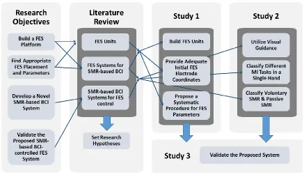
The following sections provide a brief introduction to the FES systems and SMR-based BCI systems for patients with stroke and TBI, and each section summarizes the limitations of current research studies. Thereafter, the objectives of this research study are outlined at the end of Chapter 1 (See Figure 1.1).
Figure 1.1. Research framework
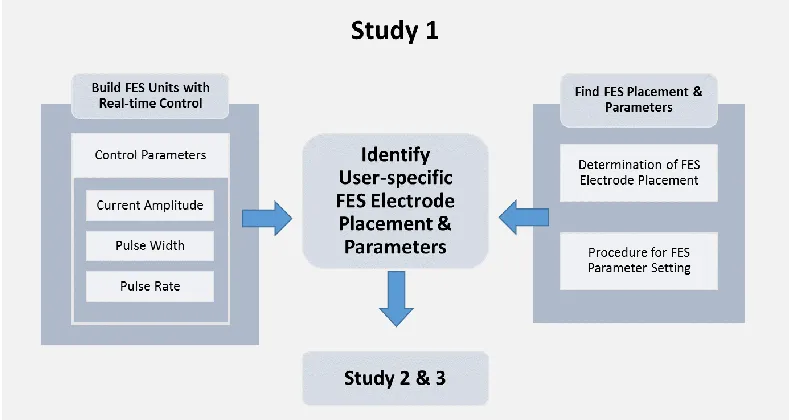
4
Chapter 3 describes Study 1 consisting of two phases, in which the FES platform was developed (See Figure 1.2). The first phase demonstrated development of customized FES units, including the characteristics of FES parameters embodied in the proposed system and the ability to control FES parameters in real-time. In the second phase, FES electrode placement was determined by considering anthropometric data to provide adequate initial FES electrode placement. In addition, the user-specific FES parameters were identified by following a systematic parameter determination procedure to enhance user satisfaction. The results of this phase could help to identify appropriate initial FES electrode coordinates and three user-specific FES parameters to restore natural hand grasping and opening motions with minimum perceived muscle pain and discomfort.
5
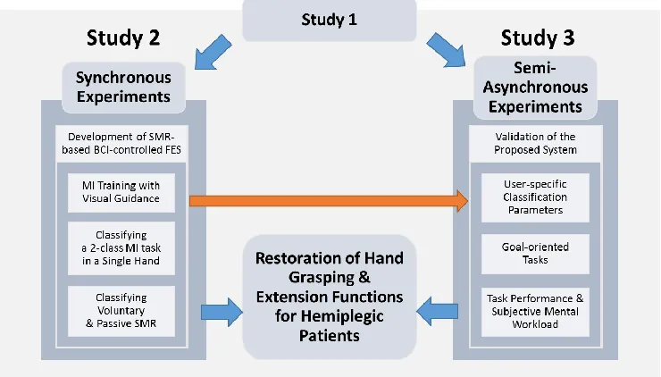
In Chapter 4, Study 2, a novel SMR-based BCI system to control FES was proposed to address the issues on current research studies by (1) providing visual guidance during MI training; (2) utilizing two different rhythmic MI tasks, such as slow one-time grasping and fast cyclic opening, to classify a 2-class MI task in a single hand, and (3) decoding different SMR inducing types, such as voluntary MI-evoked SMRs and FES-driven passive-movement-evoked SMRs. After training, the user-specific classification algorithm parameters were identified according to three roles including (1) detecting SMR, (2) classifying a 2-class MI task, and (3) decoding voluntary and passive SMRs (See Figure 1.3).
Figure 1.3. Framework of Studies 2 and 3
6 How does FES work?
1.1.1. Stroke and Traumatic Brain Injury
Each year, more than 795,000 stroke patients suffer a new or recurrent stroke in the United States, and 33 million patients suffer strokes worldwide (Lloyd-Jones et al., 2009; Mozaffarian et al., 2015). In addition, 235,000 severe Traumatic Brain Injuries (TBI) occur in the United States each year, and there are 57 million TBIs worldwide (Hirtz et al., 2007; Langlois, Rutland-Brown, & Wald, 2006). Many of these patients are susceptible to a combination of significant motor, sensory, and cognitive deficits (Langlois et al., 2006; Pereira, Teasell, Graham, & Salter, 2013), and they experience residual functional impairments (Miller et al., 2010). For instance, 25% to 62% of stroke survivors and 77% of severe TBI patients suffer from major physical complications such as spasticity and muscle weakness (Hoofien, Gilboa, Vakil, & Donovick, 2001; Wallesch, Maes, Lecomte, & Bartels, 1997; Watkins et al., 2002; Wissel et al., 2010).
7
which physical therapy, including occupational therapy, is the most common and essential (Miller et al., 2010).
1.1.2. FES Rehabilitation for Stroke and TBI Patients
The physical treatments include repeated range-of-motion exercises (Duncan et al., 2005), thermotherapy (Matsumoto et al., 2010), and electrical stimulation (Kawashima, Popovic, & Zivanovic, 2013; Quandt & Hummel, 2014). Among these physical treatment methods for patients, FES is a common adjuvant therapy and has been widely adopted as a clinical application (Lynch & Popovic, 2008; Miller et al., 2010). Levin and Hui-Chan (1992) found that repeated electrical stimulation could reduce spasticity and improve motor functions in hemiparetic patients. Sabut and colleagues (2011) also reported that conventional rehabilitation (i.e., OT) with FES treatment showed better rehabilitation outcomes than OT alone, with respect to reducing spasticity and improving muscle strength and motor recovery in stroke patients.
8
difficulties (Teasell, Bayona, & Bitensky, 2015; Wolf, 2007). Moreover, Papachristos (2014) identified the psychological benefits of utilizing FES rehabilitation, such as increasing self-esteem and reducing depression. Therefore, many research studies have been conducted with FES for motor function restoration of stroke and TBI patients (Chan, Tong, & Chung, 2009; Kawashima et al., 2013; Young, Williams, & Prabhakaran, 2014).
The FES methods can be applied to various body parts, such as the foot (Kottink et al., 2004; Sabut et al., 2011), shoulder and elbow (Aoyagi & Tsubahara, 2004; Chae, Sheffler, & Knutson, 2008), and forearm (Lawrence, 2009; Thrasher, Zivanovic, McIlroy, & Popovic, 2008). Among them, the restoration of hand function is one of the most important for patients’ independence in performing ADLs such as feeding, dressing, bathing, and making transfers (Adams, Takes, Popovic, Bulsen, & Zivanovic, 2003; Mangold, Keller, Curt, & Dietz, 2005; Popovic, Popovic, & Keller, 2002). Further support for the importance of the hand function were found in Langhorne and colleagues’ (2009) systematic review. The authors quantified the number of studies of each intervention target, and found 115 studies concerning hand and arm functions, as well as 9, 14, and 68 studies for sit-to-stand, standing balance, and gait rehabilitation for lower limbs, respectively.
9
important to benefit rehabilitation, may not be promoted well due to the lack of synchronization between a patient’s effort and physiological feedback. Neuroplasticity occurs throughout the central nervous system (Daly & Wolpaw, 2008), and is defined as the ability of the human brain to alter its structure in response to environmental demands (Draganski et al., 2004). Many research studies show the evidence of a positive effect on rehabilitation outcomes when the patient’s intentions are synchronized with the physiological feedback. Lourenção et al. (2008) showed that receiving OT and FES treatments with Electromyographic (EMG) biofeedback improved upper extremity function significantly more than receiving only OT and FES. Cauraugh and Kim (2002) utilized an EMG signal to synchronize the patient’s motor intentions and FES, and they reported that the application of EMG-triggered electrical stimulation enhanced voluntary motor control of stroke patients more than that of electrical stimulation without utilizing EMG signal.Barsi et al. (2008) also found that the combination of voluntary motor effort and electrical stimulation was more effective compared to electrical stimulation or repetitive voluntary training alone in rehabilitation of stroke patients because it had a greater potential to promote plasticity in the motor cortex. For these reasons, Takahashi et al. (2012) suggested that the FES system should synchronize between motor intention and the electrical stimulation feedback to promote neuroplasticity.
1.1.3. Limitations of Current FES Studies
10
whose EMG signals are not consistently measurable (Takahashi et al., 2012). Furthermore, EMG signals cannot be measured correctly when electrical stimulation is applied due to the higher electrical amplitude of FES than that of EMG signals (Hines, Crago, Chapman, & Billian, 1996; Minzly, Mizrahi, Hakim, & Liberson, 1993). This limitation precludes patients from utilizing EMG signals as a medium to stop or maintain the FES system when it is activated. For such patients and conditions, BCIs can be used as an alternative method to detect motor intention directly from the brain signal without residual muscle activities.
11
need to be conducted to help researchers identify appropriate FES electrode placement and parameter combinations.
How does SMR-based BCI-controlled FES work?
1.2.1. What is a BCI?
BCIs can help people to communicate and control devices and applications without using peripheral nerves and muscle pathways (Wolpaw et al., 2002). BCIs are a potential method to promote the independence of disabled persons because of the BCIs’ ability to bypass non-functional neural pathways (Daly & Wolpaw, 2008). Therefore, many researchers have endeavored to apply BCI technologies to assist disabled persons with severe neuromuscular impairments such as amyotrophic lateral sclerosis, cerebral palsy, spinal cord injury, persistent vegetative state, locked-in syndrome, TBI, and stroke complications (Brouwer & van Erp, 2010; Daly & Wolpaw, 2008; Mak & Wolpaw, 2009; Nijboer et al., 2008).
12
al., 2002). Moreover, BCI-controlled robots, games, and even music and art applications were developed to improve their quality of life (Bell, Shenoy, Chalodhorn, & Rao, 2008; Finke, Lenhardt, & Ritter, 2009; Grierson, 2008; Holz, Botrel, & Kübler, 2015; Li & Nam, 2015; Nam, Lee, Bahn, Li, & Choi, 2014; Nam, Moore, Choi, & Li, 2015).
13
1.2.2. SMR-based BCI-controlled FES Systems
One of the most studied of many BCI systems is SMR-based BCIs which utilize MIs. Beisteiner et al. (1995) defined the MI as “an imagined rehearsal of a motor act without any
overt movement” (p. 183), and SMRs induced by MIs are characterized by (de)synchronization in the alpha and beta frequency bands over the bilateral, contralateral, and ipsilateral motor cortex areas (Müller et al., 2003; Neuper, Wörtz, & Pfurtscheller, 2006; Pfurtscheller, 1977; Pfurtscheller & Aranibar, 1979). Pfurtscheller (1977) first introduced the terminology Event-Related Desynchronization (ERD) to describe event-related attenuation in the EEG signal. He then added the term Event-Related Synchronization (ERS) to explain event-related enhancement (Pfurtscheller, 1992). These SMR features, ERD and ERS, have been widely employed to decode different MIs, such as left or right-hand motor intention (McFarland, Miner, Vaughan, & Wolpaw, 2000; Pfurtscheller & Neuper, 2001; Pfurtscheller & Neuper, 1997).
14
15
1.2.3. Limitations of Current SMR-based BCIs for FES Studies
Although SMR-based BCI-controlled FES systems seem promising for rehabilitation of patients with stroke and TBI, there are three main limitations in recent research studies.
Firstly, most of the current research studies have not clearly described the procedures of MI training in the BCI systems. Brain signals vary not only from person to person, but within the same person due to the non-stationarity of brain signals (Krusienski et al., 2011; Lotte, Congedo, Lécuyer, Lamarche, & Arnaldi, 2007). Thus, machine learning techniques with a set of training procedures have been adopted to improve BCI performance (Vidaurre & Blankertz, 2010). Although there are many studies that have strived to reduce the training period (Guger, Edlinger, Harkam, Niedermayer, & Pfurtscheller, 2003; Pfurtscheller & Neuper, 2001), SMR-based BCI systems still require relatively longer training than other BCI technologies, such as steady-state evoked potential or Event Related Potential (ERP). In addition, since MI tasks to evoke SMR are mental imaginations that do not involve physical feedback, experimenters or physical therapists cannot know whether the patient is properly performing the MI tasks. To address these issues, users should to be provided with clear MI procedures for easy and efficient training. However, only few research studies focus on these issues (Blankertz, Dornhege, Krauledat, Müller, & Curio, 2007; Gatti et al., 2013; Schuster et al., 2011).
16
facilitate neuroplasticity completely due to unnatural control. It is also difficult to distinguish between voluntary MI-evoked SMRs and FES-driven passive-movement-evoked SMRs, because both conditions elicit similar brain activity (Müller et al., 2003). This result implies that it is difficult to stop or keep electrical stimulation by using SMR features because brain signals contain voluntary MI-evoked SMRs, or passive motion-evoked SMRs mixed with strong electrical artifacts.
17 The Objectives of Research
The objectives of this study were to address the limitations of current research by: 1) Developing a customized FES platform with real-time computer-controlled
functionality to realize natural hand and wrist motions via brain signals.
2) Proposing a systematic parameter determination procedure to enhance user satisfaction, as well as providing adequate initial FES electrode coordinates. 3) Proposing a novel SMR-based BCI system with visual guidelines for MI training
not only to classify a 2-class MI task between grasping and opening in a single hand, but also to decode voluntary MI-evoked SMRs and FES-driven passive-movement-evoked SMRs.
4) Validating the proposed SMR-based BCI-controlled FES system by performing goal-oriented tasks with stroke and TBI patients.
18
LITERATURE REVIEW AND SURVEY
This chapter consists of a survey and literature review. First, the anatomy of skeletal muscles for FES, as well as FES principles and guidelines were surveyed. Afterward, the FES systems used in current SMR-based BCI research studies were reviewed to identify essential elements necessary to develop a custom FES system, as well as to clarify current limitations of FES studies. In addition, SMR-based BCI research studies were reviewed to identify important features to consider in BCI systems, such as MI training methods, EEG electrode placement, and signal processing procedures including classification algorithms. This review also clarified current limitations of SMR-based BCI studies. Finally, the hypotheses were set on the basis of the survey and literature reviews according to the objectives of this study.
FES System Survey
19
2.1.1. FES Principles
Neuromuscular electrical stimulation, also known as electrical muscle stimulation or electromyostimulation, uses electrical stimulation to elicit muscle contraction (Chae et al., 2008). FES refers to the practical utilization of electrical stimulation to support or restore motor functions for patients with motor disorders, and it focuses on goal-oriented tasks such as walking, reaching, and grasping (Peckham & Knutson, 2005). Peckham and Knutson distinguished between therapeutic electrical stimulation and FES, with the former intended “to
improve tissue health or voluntary function by inducing physiological changes that remain
after the stimulation is used,” while FES intervention is used “to enable function by replacing
or assisting a person’s voluntary ability” (2005, p.328). Quandt and Hummel (2014) also distinguished between therapeutic electrical stimulation and FES, and the authors defined the role of the former as inducing physiological changes by promoting brain plasticity and improving spontaneous motor functions, and that of the latter as supplementing lost motor functions by stimulating muscles in a coordinated manner. However, these terminologies are used interchangeably by people in different fields, such as physical therapists, neuroscientists, and biomedical engineers. In this study, the definition of FES was limited to stimulating muscles to restore motor functions.
20
2001; Sujith, 2008). The stimulated muscle then contracts when the action potentials are propagated to the muscle (Popovic, Curt, Keller, & Dietz, 2001).
Electrical stimulation can be delivered via surface (transcutaneous), percutaneous, or implanted electrodes (Khamisha, 2011). Although each electrode type has its own advantages and disadvantages as shown in Table 2.1, surface electrodes are widely used because they are cheap, easy to use, and readily available on the market, unlike implanted electrodes that require surgical placement (Doucet, Lam, & Griffins, 2012; Peckham & Knutson, 2005; Popovic et al., 2001).
Table 2.1. Comparisons of different FES electrode types
(Retrieved from Peckham and Knutson (2005), Doucet et al. (2012) and Popovic et al. (2001))
Surface Percutaneous and Implanted
Electrode Position - Placed on the skin - Inserted through the skin into the nerves or muscles
Advantage
- Flexibility to support various treatments - No surgical intervention
- Easy to remove - Easy to apply
- Higher muscular selectivity - Less setup time after implantation - Minimizing discomfort
Disadvantage - Necessity of assistance to place the system - Less convenient in the ADL
- Surgical intervention - Higher cost
- Skin irritation
21
2.1.2. Precautions and Contraindications of FES
When applying FES to users, researchers should check precautions and contraindications for patients’ safety (Jones & Johnson, 2009; Reed, 1997; Rennie, 2010). Cameron (2012) distinguished contraindications and precautions as “Contraindications are conditions under which a particular treatment should not be applied, and precautions are
conditions under which a particular form of treatment should be applied with special care or
limitations” (p. 9). Reed (1997) defined four contraindications and nine precautions for
electrotherapy, and Jones and Johnson (2009) and Rennie (2010) also mentioned some contraindications and precautions. Table 2.2 summarizes the precautions and contraindications to electrotherapy in the literature review. Based on the summary, an FES safety screening questionnaire was completed (See in Appendix A). These questions should be asked to the participant before treatments or experiments and exclude participants with symptoms listed on the questionnaire.
Table 2.2. Precautions and contraindications for electrotherapy Controversy includes symptoms inconsistently classified.
(Retrieved from Reed (1997), Jones and Johnson (2009), and Rennie (2010))
Contraindications Controversy Precautions
- Unstable cardiac conditions - Implanted devices
(e.g. pacemakers) - Pregnancy
- Acute danger of Hemorrhage - Acute danger of Thromboembolism - Tuberculosis
- Over the eyes - Over head
- Epilepsy - Skin disease - Hyper/hypotension - Impaired cognition - Impaired communication - Malignancy
- Over the anterior neck
- Decreased sensation - Dysesthesia
22
2.1.3. Principal Muscles for Hand and Wrist Motions
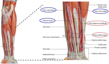
In this section, principal muscles to place FES electrodes were investigated according to each motion. For example, to generate a grasping motion that is essential for improving ADLs (Popovic, Thrasher, Zivanovic, Takaki, & Hajek, 2005), first, the wrist and thumb should be in extension with half-flexion of the four fingers before reaching an object, and the wrist and fingers should be in flexion when the object is close enough to be touched (Clarkson, 2000; Standring et al., 2008). These consecutive movements require precise coordination of extensor and flexor muscles of the fingers and wrist.
23
Figure 2.1. Superficial flexor muscles of the left forearm.
Blue solid circles indicate the flexor muscles of the wrist, and red dotted circles refer the flexor muscles of the fingers. Flexor digitorum profundus is superimposed on flexor pollicis longus.
(Modified from Gray's Anatomy. 40th Ed. p. 846, Fig. 49.12 and Fig. 49.13)
24
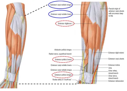
FES electrodes should be placed on those muscles. For fingers, EDC is the muscle for the extension of the four fingers, and EPL and EPB are the muscles for thumb extension.
Figure 2.2. Superficial extensor muscles of the left forearm.
Blue solid circles indicate the extensor muscles of the wrist, while red dotted circles show the extensor muscles of the fingers. (Modified from Gray's Anatomy. 40th Ed. p. 848, Fig. 49.14)
25
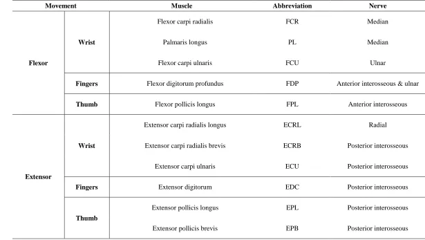
Table 2.3. Flexor and Extensor muscles on the forearm (Retrieved from Gray's Anatomy. 40th Ed. p. 784, Fig. 45.1)
Movement Muscle Abbreviation Nerve
Flexor
Wrist
Flexor carpi radialis FCR Median
Palmaris longus PL Median
Flexor carpi ulnaris FCU Ulnar
Fingers Flexor digitorum profundus FDP Anterior interosseous & ulnar
Thumb Flexor pollicis longus FPL Anterior interosseous
Extensor
Wrist
Extensor carpi radialis longus ECRL Radial
Extensor carpi radialis brevis ECRB Posterior interosseous
Extensor carpi ulnaris ECU Posterior interosseous
Fingers Extensor digitorum EDC Posterior interosseous
Thumb
Extensor pollicis longus EPL Posterior interosseous
26
2.1.4. Features in FES Operation
A few FES systems are commercially available and each system has different capabilities, such as the number of FES electrodes, current amplitude, pulse rate, pulse width, the stimulation waveform, and application of ramp time. Furthermore, various FES electrode sizes and shapes are readily available in the market.
Choosing the right number of FES electrodes and their placement is important to generate natural hand and wrist movements. For example, at least two pairs of electrical stimulation channels are required to reproduce wrist flexion and extension (Lawrence, 2009). A pair of FES electrodes, including a cathode electrode (negative, black lead) placed on wrist extensors such as ECRL, ECRB, and ECU and an anode electrode (positive, red lead) placed near the lateral epicondyle, are needed to achieve wrist extension. Another pair of FES electrodes is also required for wrist flexion, and a cathode electrode should be located on wrist flexors such as FCR, PL, and FCU, while an anode electrode should be placed near the medial epicondyle. Similarly, finger flexion and extension also require a pair of electrodes, respectively. Since the grasping force is generated by the pressure between the thumb and the other fingers, the extension and flexion of the thumb also play an important role in grasping (Bertelli, Tacca, Ghizoni, Kechele, & Santos, 2010). Therefore, four to six pairs of FES electrodes are required to perform natural hand movements such as grasping and opening.
27
between anode and cathode electrode was greater than 2 cm. Figure 2.3 illustrates an example of FES electrode placement for wrist extension and flexion of the right forearm.
Figure 2.3. Electrode placement on the right forearm for wrist extension and flexion
28
The strength of muscle contraction can be controlled by current amplitude and pulse width (Sabut et al., 2011; Thrasher et al., 2008). Pulse width, also known as pulse duration, is the stimulus time per cycle, and current amplitude is the intensity of electrical stimulus delivered by each pulse. Figure 2.4 shows examples of different current amplitudes and pulse widths. Figure 2.4 (a) indicates a 25% duty cycle (stimulation is delivered during 25% of the cycle time), while (b) shows a 50% duty cycle within the same cycle time. Figure 2.4 (c) shows a 50% duty cycle waveform with twice the amplitude shown in Figure 2.4 (a) and (b).
Figure 2.4. Examples of different current amplitude and pulse width.
(a) 25% duty cycle, (b) 50% duty cycle within the same cycle, and (c) twice amplitude than others.
29
The shape of electrical stimulus waveforms is also a feature to consider. The stimulus waveforms can be classified as monophasic or biphasic. A monophasic waveform has a single phase with a unidirectional pulse having one positive or negative phase, while a biphasic waveform has two phases with both positive and negative phases, as shown in Figure 2.5 (Martínez-Rodríguez, Bello, Fraiz, & Martinez-Bustelo, 2013). Most FES systems employ biphasic electrical stimulation because a constant polarity from monophasic stimulus can cause skin burns, muscle fatigue, and tissue damage (Martínez-Rodríguez et al., 2013; Popovic et al., 2001). The biphasic waveform can have three shapes: symmetric, balanced asymmetric, and unbalanced asymmetric. Figure 2.5 illustrates four different monophasic and biphasic waveforms. Between symmetrical and asymmetrical electrical waveforms, many studies suggest the asymmetrical waveform leads to more effective muscle control and less muscle fatigue than the symmetrical waveform (Keller, Ellis, & Dewald, 2005; Lawrence, 2009; Ragnarsson, 2008).
Figure 2.5. Monophasic and biphasic waveforms
30
Ramp time is also an important function to enhance user’s comfort. Ramp time, which typically lasts for 1 to 3 seconds, can be applied to current amplitude or pulse rate, and it indicates the duration from the beginning of stimulus to the desired current amplitude or pulse rate (Baker, Wederich, McNeal, Newsam, & Waters, 1993). Figure 2.6 shows an example of ramping in current amplitude.
Figure 2.6. Ramp time for current amplitude
(Retrieved from Figure 11.21 in Physical agents theory and practice (Behrens & Beinert, 2014))
31
muscle to generate thumb abduction, and if the cathode electrode is too large for the stimulation site, then electrical stimulation also stimulates adjacent unrelated muscles and nerves, resulting in undesirable motion. Table 2.4 lists various sizes and shapes of electrode pads using a standard 2 mm diameter lead wire with a pin connector. Figure 2.7 shows the three selected electrode pads which are readily available on the market. These electrodes contain self-adhesive hydrogel on the pad, making it easier to attach electrodes on the skin and to improve contact and electrical conductivity between the skin and electrodes (Lawrence, 2009).
Table 2.4. Various sizes and shapes of FES electrode pads
These electrodes are available on Axelgaard.com (Axelgaard Manufacturing Co., Ltd., Fallbrook, CA) and TensUnits.com (TensUnits.com, Largo, FL). All units are inches.
Oval Round Square Rectangle
1.5 X 2.5 1 2 X 2 1.3 X 2.1
2 X 4 1.25 1.5 X 1.5 1.5 X 3
3 X 5 2 2 X 3.5
2.75 2 X 5
3 3 X 4
4 2 X 4 (Dual Lead)
(a) (b) (c)
Figure 2.7. Three different types of FES electrodes with a 2 mm pin connector (a) 2" X 2" square (b) 2" round (c) 2" X 3.5" rectagle electrode pads (All units are inches)
32
2.1.5. Summary
In this section, the survey of FES systems confirms the precautions and contraindications before applying FES (Jones & Johnson, 2009; Reed, 1997; Rennie, 2010). The FES safety screening questionnaire for FES experiments is available in Appendix A, which summarized precautions and contraindications from the survey. The principal muscles for extension and flexion of the hand and wrist are also identified. Finally, the important features in building a custom FES platform are identified, such as the number of FES electrodes, FES electrode placement, pulse rate, pulse width, current amplitude, stimulation waveforms, ramp time, and FES electrode pad types.
The summary of the survey is as follows:
Surface FES electrodes are widely used because they are cheap, easy to use, and readily available on the market (Doucet et al., 2012; Peckham & Knutson, 2005; Popovic et al., 2001)
Before applying FES to participants, the investigator should check precautions and contraindications (Jones & Johnson, 2009; Reed, 1997; Rennie, 2010).
The precise coordination of flexor and extensor muscles on which FES electrodes are placed is necessary for natural hand and wrist motions (Clarkson, 2000; Standring et al., 2008).
33
To avoid muscle twitches and to achieve functional, continuous muscle contraction, pulse rate should be set above 20 Hz (Popovic et al., 2001).
The strength of muscle contraction can be controlled by current amplitude and pulse width (Sabut et al., 2011; Thrasher et al., 2008).
Asymmetric biphasic waveforms are more effective for muscle contraction, and induce less muscle fatigue than symmetrical stimulation (Keller et al., 2005; Lawrence, 2009; Ragnarsson, 2008).
Ramp time is also an important function that could improve the user’s comfort (Baker et al., 1993).
34
Review on FES Systems for SMR-based BCI
In this section, the FES systems used in SMR-based BCI studies were systematically reviewed in order to determine the scope of application of the important features defined in the previous survey needed to build a customized FES system. In the literature review, FES electrode placement and parameters used in previous research studies were summarized. Afterward, the limitations of current studies were outlined.
2.2.1. Systematic Review Procedure
For the systematical review, the Preferred Reporting Items for Systematic reviews and Meta-Analyses (PRISMA) method was applied (Liberati et al., 2009; Moher et al., 2015; Moher, Liberati, Tetzlaff, Altman, & Grp, 2009). Liberati et al. (2009) defined the aim of PRISMA as “to help ensure the clarity and transparency of reporting of systematic reviews,
35
each search engine, respectively, and 97 articles were left after removing duplicate articles. Afterward, the remaining articles were screened out based on the titles and abstracts related to BCI-controlled FES systems only. Prescreened 53 articles were checked for eligibility based on full-text screening with some exclusion criteria, such as (1) articles for non-journal, book chapter, or review papers; (2) experiments for non-human primates; (3) invasive brain imaging methods and implanted electrical stimulation systems; (4) articles for neuroscience studies that did not focus on motor function restoration, and (5) studies not related to hand and wrist control. After eligibility screening, only 18 studies remained for the review of the FES systems. Figure 2.8 shows the screening procedures and results.
Figure 2.8. PRISMA flow diagram for FES systems used in BCI studies
2.2.2. FES Systems in Current Research
36
the other six FES systems, RehaStim and Compex Motion were not commercially available in the United State in 2016, and MEB-2200 was discontinued by the manufacturer. Universal External Control Unit and MOTIONTIM 8 were also not readily available in the US market, while the design of NESS H200 was not suitable for this study.
37
Table 2.5. FES systems used in the previous studies
FES System # of
Channels Pulse Rate (Hz) Pulse Width (μs) Current Amplitude (mA)
Used Research Studies
Universal External
Control Unit 32 1 ~ 80 ~ 255 0 ~ 60 (Daly et al., 2009)
RehaStim 8 1 ~ 140 20 ~ 500 0 ~ 130 (Elnady et al., 2015; Reynolds, Osuagwu, &
Vuckovic, 2015; Vuckovic, Wallace, & Allan, 2015)
Compex Motion 4 1 ~ 100 75 ~ 16,000 0 ~ 125 (McGie et al., 2015; Tan et al., 2011)
MEB-2200 2 - - - (Mukaino et al., 2014)
MOTIONSTIM 8 8 1 ~ 99 10 ~ 500 0 ~ 125
(Pfurtscheller et al., 2003, 2005; Rohm, Muller-Putz, Kreilinger, von Ascheberg, & Rupp, 2010; Rohm et al., 2013)
NESS H200 5 18 or 36 10 ~ 500 0 ~ 150 (Roset, Gant, Prasad, & Sanchez, 2014)
Microstim
(customized) 2 1 ~ 99 ~ 250 1 ~ 99 (Kim, Kim, & Lee, 2016)
EMPI 300PV
(customized) 2 1 ~ 99 10 ~ 500 0 ~ 100 (Looned, Webb, Xiao, & Menon, 2014)
LG-7500
38
2.2.3. FES Electrode Placement and Parameters in Current Research
39
Table 2.6. Comments for electrode placement in the previous studies
Article Electrode Placement
(Daly et al., 2009) Placed over the indicis proprius muscle and the portion of the extensor digitorum communis muscle serving the index finger
(Elnady et al., 2015) Attached to the stroke affected extensor digitorum
(Tan et al., 2011) One electrode was placed proximally over the forearm below the elbow, and the other was placed distally on the forearm (positioned for optimally balanced joint movement). (Kim et al., 2016) FES was triggered and stimulated wrist extensor muscles of the affected upper extremity (Liu et al., 2014) FES is triggered and delivered to patients’ extensor carpus radialis muscles, which causes real
movement of their hands or arms
(Looned et al., 2014) Hand opening was achieved by placing two electrodes on the distal and proximal ends of the extensor digitorum muscles of the forearm [35].
(McGie et al., 2015)
Stimulate the following muscles: flexor carpi radialis, flexor digitorum superficialis, and flexor digitorum profundus (FCR/FDS/FDP), abductor pollicis brevis/ flexor pollicis brevis
(APB/FPB/OP), and extensor digitorum (for wrist/finger extension).
(Mukaino et al., 2014) Placed over the muscle belly of the extensor digitorum communis (EDC) on the paralysed side
(Pfurtscheller et al., 2003)
The finger (M. ext. digitorum communis EDC) and thumb (M. ext. pollicis longus EPL) extensors for hand opening, the finger flexors (M. flex. digitorum superficialis FDS, M. flex. digitorum profundus) hand closing, the thumb flexor (M. flex. pollicis longus FPL) for grasping and the wrist extensors (M. ext. carpi radialis longus/brevis ECRL/ECRB) for stabilization of the hand.
(Pfurtscheller et al., 2005)
An opening of the hand (phases 1 and 4, Figure 1) by extension of all fingers joints and the thumb could be achieved by stimulation of the finger extensors (M. extensor digitorum
communis) and the thumb extensor muscle (M. extensor pollicis longus) with electrodes on the radial side of the proximal forearm. For the actual grasping (phase 2, Figure 1), we
40
(Rohm et al., 2010) -
(Rohm et al., 2013)
The finger extensors (extensor digitorum communis; electrode pair (EP) 1 in Fig. 1A), the finger flexors (flexor digitorum superficialis, flexor digitorum profundus; EP 2 in Fig. 1B) and the thumb extensor (extensor pollicis longus; EP 3 in Fig. 1A) and flexor (flexor pollicis longus; EP 4 in Fig. 1B) of the right hand were stimulated via four separate pairs of surface electrodes.
(Roset et al., 2014) Extensor muscles (extensor digitorum communis and extensor pollicis brevis) (Vuckovic et al., 2015) The wrist extensor muscles (extensor carpi radialis longus).
(Tam et al., 2011) Extensor carpi radialis
(Young et al., 2014) Extensor carpi radialus brevis and extensor digitorum muscles
41
Figure 2.9. Superficial muscles in the posterior forearm.
Green circles indicate the positions to place cathode electrodes for wrist and finger extension. (Retrieved from Gray's Anatomy for Students. 2nd Ed. p. 1055, Fig. 7.88)
42
43
Table 2.7. FES parameters in the previous studies
Article Pulse Rate (Hz) Pulse Width (μs) Current Amplitude
(Daly et al., 2009) 83.3 255 Comfortable amplitude
(Elnady et al., 2015) 35 150 Comfortable amplitude
(Tan et al., 2011) 25 250 Comfortable amplitude
(Kim et al., 2016) 60 150 20 ~ 27 mA
(Liu et al., 2014) 60 150 25 mA
(Looned et al., 2014) 25 200 Comfortable amplitude
(McGie et al., 2015) 40 0 to 250 Comfortable amplitude
(Mukaino et al., 2014) 20 100 15 ~ 20 mA
(Pfurtscheller et al., 2003) 16 300 -
(Pfurtscheller et al., 2005) 18 - -
(Reynolds et al., 2015) 30 200 10 ~ 17 mA
(Rohm et al., 2010) - - -
(Rohm et al., 2013) 16 - -
(Roset et al., 2014) 35 300 Amplitude for the maximal
contraction * 1.25
(Vuckovic et al., 2015) 30 300 15 mA
(Tam et al., 2011) 40 300 50 ~ 80 mA
(Young et al., 2014) - - -
44
2.2.4. Limitations of Current Research
From the systematic literature review of the FES systems for SMR-based BCI, three main issues have been identified and are described below.
Firstly, most FES units used in the previous research were either not commercially (readily) available in the United States or did not support real-time computer control. Also, some functions, such as ramp time (Doucet et al., 2012), were not clearly specified in the articles and specification sheets provided by manufacturers.
Secondly, most of the surveyed research studies did not precisely define the exact electrode positions but vaguely described the name of the muscles where FES electrodes were placed. Furthermore, there was not clear guidance to help identify the proper electrode location with respect to anthropometric data, such as the length and mass of forearm, which varies for each individual.
45
The summary of limitations and findings in current research studies is as follows:
FES units with real-time control are not readily available in the United States. Therefore, a customized FES platform is required.
A proposed FES platform should support a sufficient number of FES electrode channels (up to 8) and a wide range of FES parameters.
Most of the studies did not precisely define the exact electrode location. There were no procedures to help identify the proper electrode position with respect to anthropometric data.
46 Review on SMR-based BCIs for FES
The objectives of this review were; (1) to analyze current FES systems, including electrode placement and parameters, controlled by SMR-based BCIs; (2) to investigate current MI training procedures and guidelines; (3) to select an EEG-channel montage used to decode MI features; (4) to define brain features evoked by MI; (5) to identify proper signal preprocessing methods to extract distinct brain features in terms of temporal and spatial filtering, and (6) to analyze current classification algorithms used for MI decoding. After the literature review, limitations of current research were outlined.
In this section, 18 articles selected in Section 2.2.1 were reused to review previous research studies from SMR-based BCI perspectives including EEG electrode placement, MI training procedures, SMR signal features, feature extraction methods, and classification algorithms. However, the studies selected in the previous section were limited to BCI studies using FES systems and did not fully cover studies on SMR-based BCIs. To address this issue, another systematic review was conducted. This systematic review identified current state-of-the-art technologies and summarized the limitations of current research studies.
2.3.1. Systematic Review Procedure
47
combinations of either “brain computer interface” or “brain machine interface”, “motor imagery” or “sensorimotor”, and “review”. After keyword searching, 35, 20, and 24 articles were found from each search engine, respectively, with 47 articles left after duplicates were removed. The remaining articles were then screened out based on the titles and abstracts related to SMR-based BCI studies.
Prescreened articles were checked for eligibility based on full-text screening with some inclusion criteria, such as (1) review articles for SMR-based BCI studies and (2) using EEG brain imaging technology. After eligibility screening, 26 studies including 18 studies from the previous review were selected for a review of SMR-based BCI. Figure 2.10 shows the steps and results of screening.
48
2.3.2. MI Instruction and Tasks in Current Research
A MI task is a mental imagination that does not involve physical movements or physiological feedback (Ang, Guan, Ang, & Cuntai Guan, 2015). This makes SMR-based BCI difficult because (1) experimenters or physical therapists cannot know whether the subject or patient completed MI tasks in the right way; (2) it is somewhat difficult to explain to users how to correctly perform MI tasks, and (3) it could be hard to maintain exactly the same MI tasks during the experiment. To address these issues, clear instructions are required to help both participants and experimenters during training. However, according to the literature review, only two studies (Kim et al., 2016; Looned et al., 2014) provided video clips as visual guidance to help subjects mimic MI tasks, while other researchers verbally explained MI tasks.
MI tasks also varied between studies. Some studies had asked participants to imagine wrist or finger movements (Daly et al., 2009; Tan, Shee, Kong, Guan, & Ang, 2011), while others asked them to imagine waving or reaching motions (Reynolds et al., 2015; Young et al., 2015). Moreover, the frequency of MI tasks varied from study to study. Three studies (Elnady et al., 2015; Mukaino et al., 2014; Reynolds et al., 2015) applied repetitive MI tasks, but other studies applied one-time MIs or did not clearly mention the frequency of MI tasks. Table 2.8 shows authors’ instructions for MI tasks mentioned in the surveyed research studies, and what the authors had asked the users to do.
49
50
Table 2.8. Instruction for MI tasks in the previous studies
Article Instruction
(Daly et al., 2009) “…attempted finger movement and relax conditions or imagined finger movement and relax conditions.” (Elnady et al., 2015) “…asked to perform different repetitive imagery tasks according to the stimulus or visual cues…” (Tan et al., 2011) “…subjects used hand grasping and wrist flexion/extension movements to elicit motor imagery.” (Kim et al., 2016) “…were advised to keep focusing on their affected arm/hand action observational tasks.” (with
video)
(Liu et al., 2014) “…a bold arrow … instructing patients to imagine left or right.”
(Looned et al., 2014) “…asked to imagine the corresponding motion for each displayed action…” (McGie et al., 2015) “…asked to perform motor imagery pertaining to a grasping movement, …”
(Mukaino et al., 2014) "…asked to attempt finger opening for 3 s at maximal voluntary effort." (at 1 Hz frequency) (Pfurtscheller et al., 2003) “…the subject imagines a foot movement, …”
(Pfurtscheller et al., 2005) “Imaginations of left versus right hand movements were carried out… single-foot motor imageries versus relaxing or hand movement imagination ...” (Reynolds et al., 2015) “…instructed to imagine waving with their right hand with a frequency of about 0.5 Hz as soon as they saw the execution cue.”
(Rohm et al., 2010) -
(Rohm et al., 2013) -
(Roset et al., 2014) “…instructed the person to either open or close his hand.” (with visual cues)
(Vuckovic et al., 2015) “…instructed to perform kinesthetic motor imagery of activities performed mentally with their left or right hand” (according to the cue) (Tam et al., 2011) “…instructed to perform motor imagery of his or her wrist on the affected side.”
(Young et al., 2014) “…taught to use attempted movements of each hand to control the BCI device.”
51
In terms of imagination tasks, some researchers applied two different conditions, rest and MI, to detecting the presence of SMR, and the user could control a device to initiate or stop the operation by classifying brain signals. In contrast, other researchers utilized two MIs, one hand MI and the other hand (or foot) MI, to classify the directional SMR. In this case, the most common cues that represented the imagination tasks found in the literature review were arrows according to target directions (Liu et al., 2014). However, in these two cases, it was impossible or unnatural to implement hand opening or closing operation through the FES system by classifying SMRs. As shown in Table 2.9, there was only one study that investigated different MI tasks within the same body part, such as imagining opening and closing in a single hand (Roset et al., 2014).
52
Table 2.9. MI Classes, analyzed band, and feature extraction methods
Article MI Classes Feature Extraction Classification Methods
(Daly et al., 2009) Attempted Movement vs.
Attempted Relaxation 3 Hz bins from 0 to 30 Hz
Time-averaged power, R-square
(Elnady et al., 2015) MI vs. Rest CSP for each electrode LDA, 10X10 CV
(Tan et al., 2011) MI vs. Rest Bandlimited multiple Fourier linear combiner with
1 Hz bin Compare mu-rhythm
(Kim et al., 2016) MI or Action Observation vs.
Rest 12 ~ 15 Hz (SMR), 16 ~ 20Hz (mid-beta)
(SMR + Middle Beta)/Theta, Threshold
(Liu et al., 2014) Left MI vs. Right MI FastICA, Tensor-based nearest feature line
distance SVM
(Looned et al., 2014) MI vs. Rest or Jaw Clench vs.
Rest 7 ~ 13 Hz (mu) and 13 ~ 30 Hz (beta) LDA
(McGie et al., 2015) MI vs. Rest 10 ~ 12 Hz and 13 ~ 15 Hz No clear
(Mukaino et al., 2014) - - -
(Pfurtscheller et al., 2003) Foot MI vs. Right Hand MI - fLDA
(Pfurtscheller et al., 2005) Both Foot MI vs. Right Hand MI - Threshold
(Reynolds et al., 2015) Left Hand MI vs. Right Hand MI Select significant band by t-percentile bootstrap LDA
(Rohm et al., 2010) Feet MI vs. Hands MI - -
(Rohm et al., 2013) Foot MI vs. Right Hand MI Select the most reactive band power features LDA
(Roset et al., 2014) Hand Open MI vs. Hand Close
MI PSD from FFT with 1Hz bin
Normalized PSD z-scores & Actor-critic Reinforcement Learning Algorithm
(Vuckovic et al., 2015) Left Hand MI vs. Right Hand MI delta, theta, mu/alpha, beta1 (12 ~ 16), beta2 (16 ~
24), PSD Threshold
(Tam et al., 2011) Left Hand MI vs. Right Hand MI CSP fLDA, Adaptive (Last 6
trials)
(Young et al., 2014) Attempted Movements (Right
vs. Left) vs. Rest
Determine channels with the largest r-squared
values, ERD -
(Young et al., 2015) Left Hand MI vs. Right Hand MI
53
2.3.3. Signal Processing for SMR-based BCIs
The signal processing procedure for SMR-based BCI system shown in Figure 2.11 consists of five consecutive steps such as signal acquisition, preprocessing, feature extraction & selection, classification, and application control. In this section, the state of the art in each signal processing stage was summarized from the literature review.
Figure 2.11. Flow diagram for signal processing
Signal Acquisition
54
computation time and higher complexity for signal processing (Wang, Miao, & Blohm, 2012). Furthermore, from an HF/E perspective, the use of many electrode channels could reduce user satisfaction by increasing the set-up time and the conductive gel applied to the scalp (Zickler et al., 2011). Figure 2.12 shows the layout of