Influence of Process Parameters on the Deep
Drawing of AL 6061 Sheet
Maninder Singh
1Narinder Kumar
2P.G. Student, Department of Mechanical Engineering, RBIEBT College, Kharar, Distt. Mohali, Punjab, India1
Assistant Professor, Department of Mechanical Engineering, RBIEBT College, Kharar, Distt. Mohali, Punjab, India2
ABSTRACT: Deep drawing is a most important technique for forming sheet metal parts. It is widely used for mass production of cup shapes in automobile, aerospace and packaging industries. Defectives due to wrinkles and excessive roughness alter the product geometry from the designed one, causing difficulties in finishing of sheet products. These defects directly lead to increase the manufacturing cost. Surface roughness and uniform wall thickness are the major challenges in the deep drawing process. Three process parameters namely blank holder force, die shoulder radius and punch nose radius were optimized in this research to achieve good surface finish and uniform wall thickness. By Using TAGUCHI’s signal-to-noise ratio, it is determined that the optimum levels of the above three factors, for the most even surface finish, are found to be blank holder force of 8 KN, die shoulder radius of 8 mm and punch nose radius of 5mm which is 1.55 μm. Similarly, for wall thickness the optimum levels of the above three factors, for the most even wall thickness, are found to be blank holder force of 6 KN, die shoulder radius of 4 mm and punch nose radius of 5mm which is 1.36mm. By using ANOVA it is also concluded that the blank holder force has major influence followed by die shoulder radius and punch nose radius on the surface roughness and wall thickness of the deep drawn cup of AL 6061 sheet.
KEYWORDS:deep drawing; aluminium alloy; surface roughness; thickness distribution; signal to noise ratio I. INTRODUCTION
Deep drawing is one of the most important processes for forming sheet metal parts. Sheet metal forming is mostly used in manufacturing processes for the fabrication of a wide range of products in many industries. Deep drawing is one of the extensively used sheet metal forming processes in the industries to have mass production of cup shaped components in a very short time. It is widely used for mass production of cup shapes in automobile, aerospace and packaging industries. Sheet metal forming is a technique by which most body parts are produced in automobile industries. In sheet metal forming, a thin blank sheet is subjected to plastic deformation using forming tools to conform to a designed shape. During this process, the blank sheet is likely to develop defects if the process parameters are not selected properly. Therefore, it is important to optimize the process parameters to avoid defects in the parts and to minimize production cost. Optimization of the process parameters such as die radius, blank holder force, friction coefficient, etc., can be accomplished based on their degree of importance on the sheet metal forming characteristics. In this investigation, a statistical approach based on Taguchi technique has been adopted to determine the degree of importance of each of the
process-parameters on the thickness distribution of deep drawn circular cup. Taguchi method [1]has been applied in
forming studies to design the experiments and determine the influence of process parameters on characteristics of the formed part. In this study influence of process parameter on the surface roughness of formed part was identified. Mark
Colgan et al. (2008) reported preliminary study made on the influence of process parameters in deep-drawing process
[2]. Taguchi L8 orthogonal array was used to investigate the effect of seven process parameters in eight experiments.
The results indicate that the punch/die radii have the greatest effect on the thickness of the deformed mild steel cups
compared to other process parameters. S. Raju et al (2010) determined that the die shoulder radius has major influence
followed by blank holder force and punch nose radius on the thickness distribution of the deep drawn cup of AL 6061
sheet [3]. Davidson et al. (2008) used Taguchi method to optimize flow-forming process for maximum deformation of
the formed tube. The surface roughness of the flow-formed tube was predicted by Davidson et al. (2008) using
of three process parameters in nine experiments. The process parameters have studied are, the punch radius, the die radius, the blank holder force. The influence of process parameter on the surface roughness and wall thickness of formed part have identified.
II. EXPERIMENTATION 2.1 Material Used
The material used in this work was commercially available AL 6061 aluminium alloy sheet. The thickness of the sheet was 1.5 mm.
It is very important to check the Chemical composition of material before performing experiments. Chemical composition Al6061 is shown in table 1.
Table 1: Chemical composition of Al6061
Cu Mg Si Fe Pb
0.239 0.9 0.401 0.55 0.0428
Zn Ti Cr Other AL
0.222 0.142 0.0477 0.05 Balance
2.2 Parameters and levels
The formability of a blank sheet depends on the process parameters such as blank holder force, lubrication, punch and die radii, die–punch clearance, in addition to mechanical properties and thickness of the sheet metal and part’s geometry.
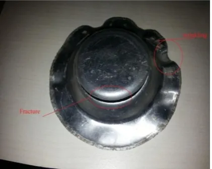
Figure 1. Shows the fracture and wrinkle are the two major modes of failure in sheet metal parts.
Fig. 1: Failure in sheet metal parts
Hence, using proper blank holder force is an essential criterion to restrict wrinkling tendency and avoid tearing of the blank sheet. Previous research on these failure modes highlights the role of blank holder force in forming and suggests
force, the die radius and the punch radius control the metal flow into the die cavity in deep-drawing process [9–11].
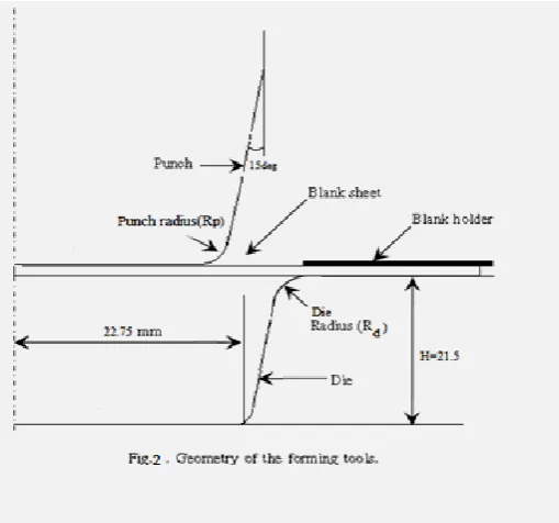
The flow of material into the die cavity reduces with small die radius while a large die radius lead to wastage in trimming excess material and induces spring back characteristic. An appropriate die radius allows smooth flow of materials on one hand and reduces spring back and material wastage. Similarly, appropriate punch radius allows smooth flow of materials and good surface finish. Geometry of tool is shown in fig 2.
All these parameters were selected according to the benchmark specification given in Numisheet 2002[12].
In Taguchi design, orthogonal array for the three parameters (Blank holding force, Die shoulder radius (Rd) mm, Punch
nose radius (Rp) mm) with three levels. is shown in table 2.
Table 2: Process parameters and their levels
Process parameter
Levels and Their range
-1 0 1
(A)Blank holding force (Fb)KN 4 6 8
(B)Die shoulder radius (Rd)mm 4 6 8
(C)Punch nose radius (Rp)mm 4 5 6
The high order interactions among the above three factors are assumed negligible and the information on the main
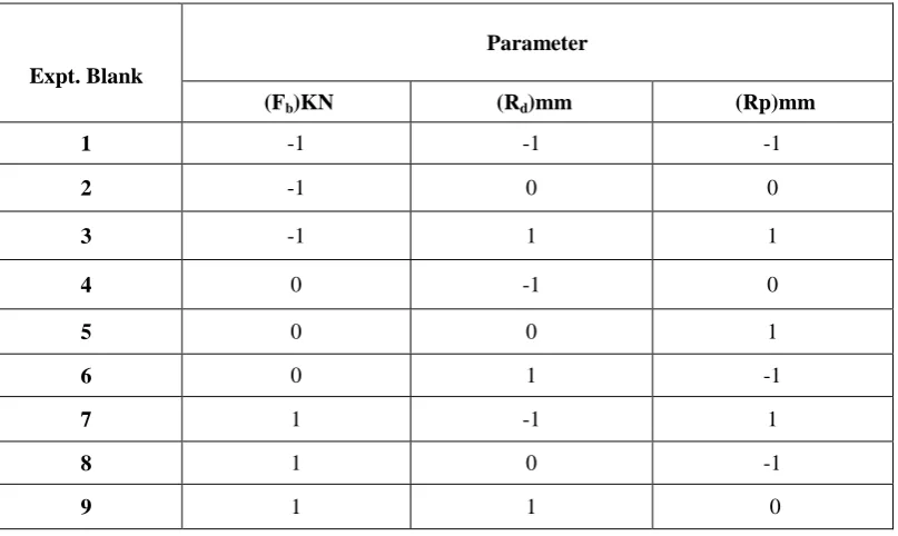
Table 3 shows the appropriate Taguchi orthogonal array for the above three parameters with three levels is L9 to conduct nine simulations. The first column represents the number of simulation and the subsequent columns represent the process parameters and the rows represent simulations with the levels of each parameter.
Table 3: Orthogonal array (L9) of Taguchi method
Expt. Blank
Parameter
(Fb)KN (Rd)mm (Rp)mm
1 -1 -1 -1
2 -1 0 0
3 -1 1 1
4 0 -1 0
5 0 0 1
6 0 1 -1
7 1 -1 1
8 1 0 -1
9 1 1 0
III.CONDUCTINGEXPERIMENTS
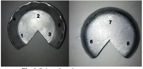
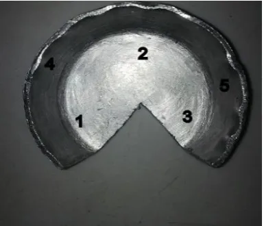
The deep drawing was conducted on hydraulic press. The blanks of 83 mm in diameter were cut from the sheet and cups were drawn according to the experimental design. Cut section of the cups are shown in fig.3
IV.RESULTSANDDISCUSSION
Figure 4 shows the drawn cups were sectioned and the roughness was measured at eight points both inner and outer. This measurement was done all nine cups.
Fig. 4: Points of roughness measurements
Table 4 shows all the measured values of roughness which were measured along the eight points of cups. There were nine experiments all the value of roughness is shows in nine rows. Eventually their average was used to predict the optimal parameters.
Table 4: The measured roughness values
Exp No. Roughness checking positions (RA)
1 2 3 4 5 6 7 8
1 1.75 1.79 1.85 1.836 1.79 1.86 1.88 1.78
2 1.75 1.833 1.87 1.853 1.781 1.79 1.77 1.86
3 1.71 1.68 1.79 1.86 1.72 1.56 1.64 1.76
4 1.54 1.81 2.73 1.76 1.89 1.68 1.46 1.69
5 1.46 1.48 1.65 1.15 1.67 1.92 1.86 1.78
6 1.16 1.21 1.71 1.65 1.72 1.86 1.7 1.56
7 1.53 1.98 1.62 1.31 1.4 1.64 1.45 1.73
8 1.62 1.56 1.67 1.64 1.35 1.41 1.53 1.6
9 1.66 1.5 1.69 1.61 1.52 1.53 1.45 1.5
Table 5 shows the level average response analysis for roughness by S/N ratio. By observing this table raking of
parameters is determined and it is observed that blank holding has major effect.
Table 5: Response Table for Signal to Noise Ratios Smaller is better (surface roughness)
Level A B C
1 -5.032 -4.905 -4.394
2 -4.441 -4.496 -4.817
3 -4.14 -4.213 -4.402
Delta 0.892 0.692 0.422
By observing Fig. 5 for roughness the optimum levels of the above three factors, for the most even surface finish, are found to be blank holder force of 8 KN, die shoulder radius of 8 mm and punch nose radius of 5mm, which are the parameter level settings for the experimental No.9
1 0 -1 -3.0 -3.5 -4.0 -4.5 -5.0 1 0 -1 1 0 -1 -3.0 -3.5 -4.0 -4.5 -5.0 (Fb)KN M e a n o f S N r a t io s (Rd)mm (Rp)mm
Main Effects Plot for SN ratios Data Means
Signal-to-noise: Smaller is better
3 2 1 1.8 1.7 1.6 1.5 1.4 3 2 1 3 2 1 1.8 1.7 1.6 1.5 1.4 A M e a n o f M e a n s B C
Main Effects Plot for Means Data Means
Fig 5: S/N plots for roughness .
Uniform wall thickness the major challenges in the deep drawing process. Similarly, the thickness was measured at five points. Figure 4 shows the drawn cups were sectioned and the thickness was measured at five points. This measurement was done all nine cups.
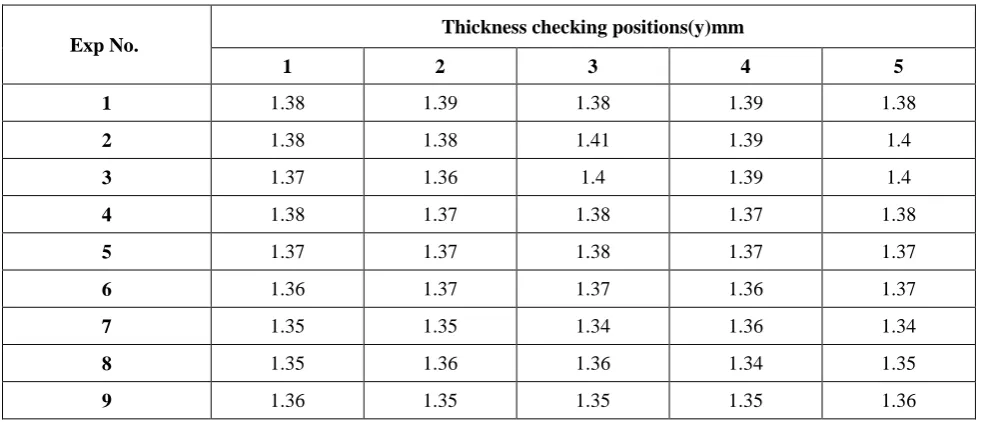
Table 6 shows all the measured values of thickness which were measured along the five points of cups. There were nine experiments all the value of roughness is shows in nine rows. Eventually their average was used to predict the optimal parameters.
Table 6: The measured Thickness values
Exp No.
Thickness checking positions(y)mm
1 2 3 4 5
1 1.38 1.39 1.38 1.39 1.38
2 1.38 1.38 1.41 1.39 1.4
3 1.37 1.36 1.4 1.39 1.4
4 1.38 1.37 1.38 1.37 1.38
5 1.37 1.37 1.38 1.37 1.37
6 1.36 1.37 1.37 1.36 1.37
7 1.35 1.35 1.34 1.36 1.34
8 1.35 1.36 1.36 1.34 1.35
9 1.36 1.35 1.35 1.35 1.36
Table 7 shows the level average response analysis for roughness by S/N ratio. By observing this table raking of
parameters is determined and it is observed that blank holding has major effect.
Table 7: Response Table for Signal to Noise Ratios higher is better (wall thickness)
Level A B C
1 1.385 1.368 1.366
2 1.371 1.372 1.374
3 1.351 1.368 1.368
Delta 0.034 0.004 0.008
By observing Fig. 7 for thickness the optimum levels of the above three factors, for the most even wall thickness, are
found to be blank holder force of 6 KN, die shoulder radius of 4 mm and punch nose radius of 5mm, which are the
parameter level settings for the experimental No.4.
3 2 1 2.85 2.80 2.75 2.70 2.65 3 2 1 3 2 1 2.85 2.80 2.75 2.70 2.65 A M e a n o f S N r a ti o s B C
Main Effects Plot for SN ratios
Data Means
Signal-to-noise: Larger is better
Fig 7: S/N plot for thickness
V. ANOVAANALYSIS
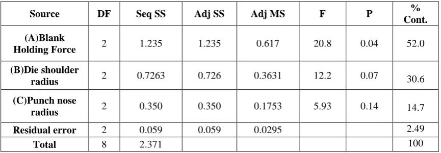
(a) Percentage Contribution for Surface Roughness Utilizing Minitab Software:
In ANOVA analysis F-test was conduct to compare a model variance with a residual variance. F value was calculated from model mean square divided by residual mean square value.
Table 8 shows the analysis of variance was calculated for cups and percentage contribution. By observing this table it was determined that the blank holding force has major contribution 52% followed by die radius 30.6% and punch radius 14.7%.
Table: 8 Analysis of variance
Source DF Seq SS Adj SS Adj MS F P % Cont. (A)Blank
Holding Force 2 1.235 1.235 0.617 20.8 0.04 52.0 (B)Die shoulder
radius 2 0.7263 0.726 0.3631 12.2 0.07 30.6 (C)Punch nose
radius 2 0.350 0.350 0.1753 5.93 0.14 14.7 Residual error 2 0.059 0.059 0.0295 2.49
(b) Percentage Contribution For wall Thickness Utilizing Minitab Software:
Table 9 shows the analysis of variance was calculated for cups and percentage contribution. By observing this table it was determined that the blank holding force has major contribution 56.3% followed by die radius 22.4.6% and punch radius 19.7%.
Table 9: ANOVA for SN ratios (wall thickness)
Source D
F Seq SS Adj SS Adj MS F P
% Cont (A)Blank
Holding Force 2 0.0025 0.0025 0.0012 38.4 0.025 56.3 (B)Die
shoulder radius
2 0.0009 0.0009 0.0004 15.3 0.061 22.4
(C)Punch nose
radius 2 0.0008 0.0008 0.0004 13.5 0.069 19.7 Residual error 2 0.00006 0.00006 0.00003 1.46
Total 8 0.0044 100
VI.CONCLUSION
From the results, S/N proportion and ANOVA examination and anticipated ideal drawing parameters, the accompanying conclusions are drawn:-
• It is observed that blank holding force has a more prominent impact on the both surface Roughness and thickness.
Punch nose had the minimum impact on Roughness.
• The optimal setting of procedure parameters for surface roughness is 8 KN, punch nose range of 5mm, and die
shoulder radius of 8 mm.
• The experimental estimated value of roughness when took the parameters 8 KN, punch nose radius of 5mm, and die
shoulder range of 8 mm is 1.55 μm.
• The optimal setting of procedure parameters for even wall thickness is be blank holder force of 6 KN, die shoulder
radius of 4 mm and punch nose range of 5mm.
• The experimental estimated value of wall thickness when took the parameters blank holder force of 6 KN, die
shoulder radius of 4 mm and punch nose range of 5mm is 1.36mm.
REFERENCES
[1] G. Taguchi, S. Konishi, “Taguchi method, orthogonal arrays and linear graphs, Tools for Quality Engineering” American Supplier Institute” 1987 pp. 35–38.
[2] M. Colgan, J. Monaghan, “ Deep drawing process: analysis andexperiment” Technol. 132 (2003) 35–41.
[3] S. RAJU, et al/Trans. Nonferrous Met. Soc. “Influence of variables in deep drawing of AA 6061 sheet” China 20(2010) 1856−1862. [4] Davidson M.J., Balasubramanian K. and Tagore G.R.N., 2008. “Modelling of Aging Treatment of Flow-Formed AA6061” Vol. 23, No. 5,
pp. 538–542..
[5] L. Gunnarsson, E. Schedin, “Improving the properties of exterior body panels in automobiles using variable blank holder force” Process. Technol. 114 (2001) 168–173.
[7] Z.Q. Sheng, S. Jirathearanat, T. Altan, “Adaptive FEM simulation for prediction of variable blank holder force in conical cup drawing”, Int. J.Mach. Tools Manuf. 44 (2004) 487–494.
[8] S. Yoshihara, K.-I. Manabe, H. Nishimura, “Effect of blank holder force control in deep-drawing process of magnesium alloy sheet” J. Mater. Process. Technol. 170 (2005) 579–585.
[9] D.-K. Leu, “The limiting drawing ratio for plastic instability of the cup drawing process” J. Mater. Process. Technol. 86 (1999) 168–176. [10] L. Duchêne, A.M. Habraken, “Analysis of the sensitivity of FEM predictions to numerical parameters in deep drawing simulations” Eur.
J. Mech. A/Solids 24 (2005) 614–629.
[11] R.K. Verma, S. Chandra,” An improved model for predicting limiting drawing ratio” J. Mater. Process. Technol. 172 (2006) 218–224 [12] Numisheet 2002, “Design innovation through virtual manufacturing” [C]//Proceedings of the 5th International Conference and Workshop