Design And Analysis Of Kinetic Energy Recovery System In Bicycles
Full text
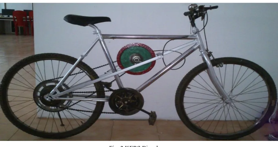
Figure


Related documents
Comparison of caring burden subscales’ means after the intervention in the study and control groups, through independent t ‑test, showed a significant difference in time
To improve patients’ diabetes self-management behaviors, health care providers should cultivate patient-cen- tered relationships that respect patient autonomy; organize their clinic
The data link service provides functions required for the transfer of user plane data and control plane data over the LDACS sub-network. The security service provides functions
SASL is used to provide support for authentication and security services to connections-. based protocols, such as the SMTP and POP3 protocols that are employed on
b. Loans to be taken from banks and financial institutions c. Public deposits to be drawn like in form of bonds. Choice of factor will depend on relative merits and demerits of
HEREDIA: Barva, P. Braulio Carrillo, Sector Volcán Barva, D. Griffin et al. SAN JOSÉ: Dota, San Gerardo, Río Savegre, A.. Jack) Fulford ALAJUELA: Poás, P.. Without locality,
Each pupil will receive an end of year target and an end of year 11 target in each subject. Progress of pupils is compared to these targets during their time at Madeley. This process
By overlapping the 5hmC profiles from normal tissues and vitamin C-treated T24 cells, we identified 2511 RefSeq genes with decreased 5hmC densities in bladder cancer tissue that
