Voltage Stability for a 11kV Libyan
Distribution Network to Address Future
Requirements
Mustafa Ali Elsherif 1, Abdalla M. BenGhuzzi2, Ahmed A. Baaiu3
Lecturer, Department of Electrical Engineering, Faculty of Engineering, Misurata University, Libya1 Assistant Lecturer, Department of Electrical Engineering, College of Industrial Technology, Misurata, Libya2 Assistant Professor , Department of Electrical Engineering, Faculty of Engineering, Misurata University, Libya3
ABSTRACT: The increase of power demand in Libya raises the voltage drop issues in distribution networks.
Therefore, Integrating renewable energy sources into electrical distribution networks as distributed generation (DGs) would play an essential role to overcome many issues such as meet future demand, eliminate voltage drop issues and decrease the CO2 emissions in Libya distribution networks. However, connecting many DGs into the distribution
networks will cause the voltage regulation and stability challenges. This paper looks at the voltage performance for a real 11kV Libyan distribution network at current and future demands to discover whether the existing technologies in the network could maintain the voltage levels within required limits ±6%. Additionally, the appropriate location of connecting a future renewable power station into this network is investigated in terms to avoid voltage regulation issue occurs in the network at future requirements.
KEY WORDS:Voltage changes level; on-load tap changer transformer; future demands; renewable energy sources.
I. INTRODUCTION
The Voltage regulation issues have in recent years begun to pose an undesirable threat to the operational stability of distribution power systems in Libya. The annual power demand in Libya is an increase significantly by 6 – 8 % of total current demand [1]. The demand in Libya was 5.8GW by 2010. Then, the demand is excepting to reach 8GW by 2020[1]. The increase of demand leads to raise the voltage drop issues in the distribution networks. Many conventional techniques such as On-load tap changer transformer (OLTCT), Automatic voltage regulations (AVR) and governor in DGs, capacitor banks and voltage regulators, can implement into distribution networks to maintain the voltage level within required limits [2]. However, operating many DGs into distribution networks increases issues associated with stability, power management and voltage regulation.
Moreover, meeting the future demand with considering reduction of CO2 emission in Libya is required to start
integrating renewable energy source as DGs into the distribution network. Hence, connecting future renewable energy stations will play essential role to address such issues in the future. Advantages of integrating these DGs into distribution networks can enhance power support, reduced power losses and improved voltage profile [3, 4].However, operating many DGs into distribution networks increases issues associated with stability, power management and voltage regulation [5].
II. CONTROL VOLTAGE LEVEL IN DISTRIBUTION NETWORKS
Voltage drop issues is a major problem in many Libyan distribution networks, especially those operating at lower voltage levels and those feeding large loads over long distance at poor power factor. Maintain voltage level within required limits in these networks is challenging especially with the expected future demands [2]. Furthermore, connecting more DGs into distribution networks lead to increasing voltage stability issues. There are many techniques are implemented with conventional distribution networks to maintain the voltage level within required limits such as sharing reactive power between generators. Actually, control sharing reactive between DGs has a huge influence to control the voltage level in distribution networks especially those have heavy loads or poor power factor for loads. Several studies propose the sharing of reactive power between DGs in conventional distribution networks. A solution to the problem of operating heavy loads with non-unity lagging power factors in distribution networks by sharing reactive power between two DGs is proposed in [6]. It shows that the DGs can be used in the network to reduce the reactive power losses if they already exist in the network. One DG is used to supply to where the reactive power is needed in the network to avoid delivering reactive power through the distribution network [6]. The sharing of reactive power between these DGs is accomplished by an automatic power factor regulator (APFR), which allows a heavy load to be supplied while simultaneously maintaining the voltage within the required limits. In [7], the sharing of reactive power between DGs is proposed to supply heavy loads and to keep the voltage within network limits. The sharing of reactive power between DGs in this case is achieved through the DG AVRs to control the output of reactive power from each DG. Occasionally, on-load tap-changing transformers must be used in conjunction with DGs when the DGs are unable to maintain the voltage within the saturation limits. In [6]and [7], on-load tap-changing transformers are used to maintain the voltage within required limits when one of the DGs goes off-line for some reason such as the occurrence of a fault or when the DGs supply heavy loads by sharing reactive power between them. Thus, on-load tap-changing transformers need to be used in order to help the DGs to maintain the voltage within limits. A further use for on-load tap-changing transformers is in conventional distribution networks when the sharing of reactive power needs to be balanced equally between DGs [7]. Furthermore, connecting more DGs into distribution networks lead to increasing voltage stability issues. The voltage drop in distribution networks can represented by following equation, equation 1.
∆V = −j (1)
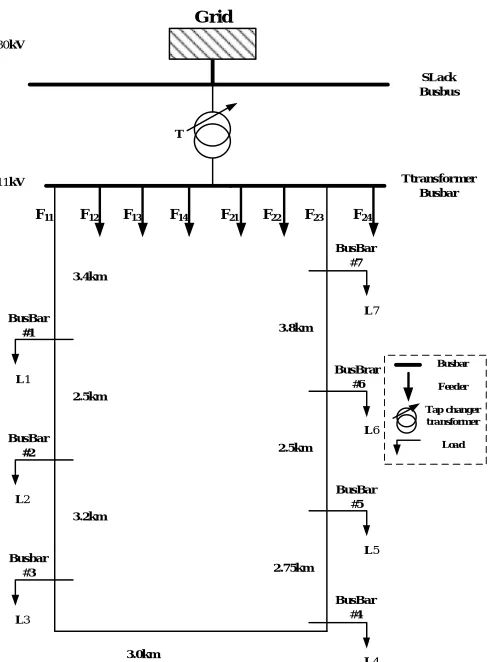
III.CASE STUDY
30kV
11kV
3.4km
SLack Busbus
Ttransformer Busbar
BusBar
#7
BusBrar
#6
BusBar
#5
BusBar
#4 Busbar
#3 BusBar
#2 BusBar
#1
L1
L2
L3
L4
L5
L6
L7
2.5km
3.2km
3.0km
2.75km 2.5km 3.8km
F11 F12 F13 F14 F21 F22 F23 F24
Grid
T
Busbar
Feeder
Tap changer transformer
Load
Fig. 1 The 11 kV Libyan distribution network with composite load
IV.MODELLING OF THE ON LOAD-TAP CHANGER TRANSFORMER CONTROL SYSTEMS
Recalling that the aim of the controller of tap changer transformer is to maintain the voltage level in the distribution network within ± 6% from the slack busbar voltage. The tap-changing steps move in up and down directions to adjust the secondary voltage of the transformer. The change of tap position is carrying out in discrete steps with each beginning at 0.0125% of the normal ratio according to transform specifications that used in this real network. The function below is programming in C++ and it is expressing mathematically for controller.
01
.
0
0
0
01
.
0
1
0
1
in in in
controller
V
V
V
f
(2)
voltage in the distribution network within ±0.06 pu. The control system of the tap changer transformer begins to work after 30 seconds and once the tap position is set, it holds for 10 seconds before the next change of tap position can take place [9]. The number of steps that made is ± 16 steps [10]. Figure 2 shows the diagram of the whole controller for tap changer transformer.
Fig. 2 The diagram of the controller for tap changer transformer
Where, V measurement is the input voltage from transformer busbar, V errors the voltage error from comparison between the input voltage and reference voltage, VD is the output of the time delay unit, Vn represents an incremental change in tap position and Tap position is reflected in the transformer model.
V. ANALYSIS OF VOLTAGE CHANGES
The analysis of voltage level changes investigates to find out whether the existing OLTCT can be kept the voltage within required limits. The investigation is look at the voltage level changes occur in a real 11kV Libyan distribution network at current peak and future demands.
Current Peak Demand:
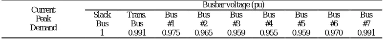
This case investigated the voltage changes in the 11 kV Libyan distribution network at early evening peak demand. Demand reaches peak value in the summer and winter seasons[11].In the Libya, June, July and August are considered the summer peak demand and December, January and February as the winter peak demand, therefore the highest power demand has been taken based on these assumptions for this study to investigate the voltage level changes that occur in the 11kV Libyan distribution networks at the current peak demand [11,12]. The peak demand for this study is 20MVA at 0.9 lagging power factor. In this case, the tap changer of OLTCT does not moved when the voltage level was above 0.99 pu in terminal busbar of transformer. That means, the error occurs in ONTC controller was within bandwidth. Therefore, the voltage level in the 11kV Libyan distribution network kept at requirement limit (±6%) from voltage of slack busbar. Table 1 shows the voltage changes in the 11kV Libyan distribution network with step up of tap changer transformer.
Table 1. The voltage changes in the 11kV Libyan distribution network with step up of tap changer transformer at peak demand (20MVA).
Future demand
In this case, the voltage level changes in the 11kV Libyan distribution network have been evaluated at future demand. This investigation needs to be implemented to find out whether the present 11kV Libyan distribution network can cope with future demand using existing OLTCT without resulting any voltage drop issues. The power demand in Libya is increased by 8% of total current demand [1]. Consequently, this percentage of increased demand has added to current
Measuring element
Time Delay elements
Motor Drive Unit
Tap Changer
measurment
V
refrence
V
error
V
D
V Vn Tapposition
Busbar voltage (pu) Current
Peak Demand
Bus #7 Bus
#6 Bus
#5 Bus
#4 Bus
#3 Bus
#2 Bus
#1 Trans.
Bus Slack
Bus
0.991 0.970 0.959 0.955 0.959 0.965 0.975 0.991
peak demand to obtain of the future demand after 10 years. Figure 3 introduces the power demand changes through 10 years in the 11kV Libyan distribution network.
Fig 3. The power demand changes through 10 years in the 11kV Libyan distribution network
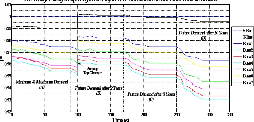
As show in figure 4, the tap changer transformer has moved once the voltage drop less than 0.99 pu for terminal busbar of transformer. Although the voltage level in the 11kV Libyan distribution network has dropped down less than 0.94 pu at busbar #3, busbar #4and busbar #5,the tap changer transformer has not move because the error of voltage changes is within bandwidth for OLTCT controller as shown in figure 4. Hence, the tap changer transformer controller has not operated to maintain voltage in the network. This indicates that the necessary of integrating distributed generation (DGs) to address challenges those face the 11kV Libyan network such as to avoid voltage regulation issue occur, to meet future demand and to decrease the CO2 emissions in Libya.
Fig.4 The voltage changes in 11kV Libyan distribution network through 10 years
0 50 100 150 200 250 300 330
1 1.5 2 2.5 3 3.5
4x 10
7
Time (s)
M
V
A
Variable Demand
Future Demand after 10 Years (D)
Future Demand after 5 Years (C)
Future Demand after 2 Years (B)
Mininum & Maximum Demand (A)
0 50 100 150 200 250 300 330
0.92 0.93 0.94 0.95 0.96 0.97 0.98 0.99 1 1.01
Time (s)
p
u
The Voltage Changes Expecting in the Libyan 11kV Distribution Network with Variable Demand
S-Bus T-Bus Bus#1 Bus#2 Bus#3 Bus#4 Bus#5 Bus#6 Bus#7 Ste p up
Tap Change r
Mininum & Maximum Demand
(A) Future Demand after 2 Years
(B) Future Demand after 5 Years
(C)
VI.INTEGRATION OF FUTURE RENEWABLE ENERGY STATION
Although the X/R ratio of distribution networks is lower than for transmission networks it is often still effective to control voltages in distribution networks through power control. Ideally, it must take as close to the source of voltage deviations as possible. Renewable energy sources as DGs will increasingly be located in disparate locations. Therefore, in many cases it is more desirable to call upon DGs to meet future demand. The future Photovoltaic (PV) power substation is associated at the weakest busbar in the network at peak demand, which is busbar #4. Figure 5 indicates the ideal location of PV power station as DG to overcome of issues that previously mentioned before [13].
30kV
11kV
3.4km
SLack Busbus
Ttransformer Busbar
Busbar
#7
Busbar
#6
Busbar
#5
Busbar
#4 Busbar
#3 Busbar
#2 Busbar
#1
L1
L2
L3
L4
L5
L6
L7
2.5km
3.2km
3.0km
2.75km 2.5km 3.8km T
F11 F12 F13 F14 F21 F22 F23 F24
Busbar
Feeder
Tap changer transformer
Load
PV Power Station Grid
PV Power Station
Fig.5 Ideal location of integration renewable resources into the 11kV Libyan distribution network
The studying of possibility to integrate renewable energies as DGs provides to find out how much power can injected by these DGs to maintain voltage within required limits. The analysis is carried out to investigate how much power can be delivered from DGs in the 11kV Libyan distribution network before voltage level reaches to over 1.06 pu in the network. Moreover, it is investigated how much power can be delivered from DGs in the 11kV Libyan distribution network at future to bring the voltage level to 0.94 pu in the network.
level goes over 1.06 pu in the 11kV Libyan distribution network. Table 2 shows the voltage changes in the network with/without connecting future PV power station at minimum and peak demand
.
Table 2. The voltage changes in the network with/without future PV power station at minimum demand
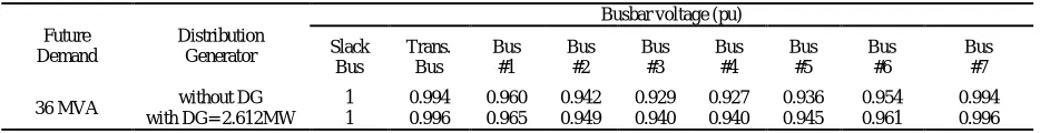
Table 3.The voltage changes in the network with/without future PV power station at peak demand
The future PV power station is assumption to be operated at 1 power factor .Therefore, there is no reactive power generated from this substation in this study. Based on results in table 3,the maximum power can be injected from future PV power station at future power demand (36MVA) is 2.61MVA to bring voltage level to 0.94pu in busbar #3, busbar #4 and busbar #5. Moreover, the maximum power can be injected from future PV power station at minimum power demand (16MVA) is 28.2MW before the voltage regulator issue occurs as shown in table2. However, the number of cables has increased to deliver that amount of power in the network. This indicates that the necessary of introduce a method to cooperate of tap changer transformer and distributed generator to fed and to maintain voltage level within required limits at current and future demand. Consequently, the power management systems(PMS) controller could be designed to operate as supervision for tap changer transformer controller, and DGs to meet future requirements.
VII. CONCLUSION
In this paper, the investigation of voltage performance at the real 11kV distribution network has investigation at current and future demand to meet future demand. The results provide that the existing tap changer transformer could not be able to maintain voltage within required limits after approximately 10 years from now. Consequently, the proposal to integrate a future PV power station is introduced to overcome such issues of voltage stability those would face the real 11kV Libyan distribution network in the soon future. The maximum power can be injected from the future PV power station at minimum demand is 28.2MW before voltage regulation issue occurs. Moreover, the maximum power can be injected from the future PV power station at future demand is 2.61MW to bring voltage level limit within required limit. This indicates that the necessary of introduce a method to cooperate of tap changer transformer and distributed generator to fed and to maintain voltage level within required limits at current and future demand with reasonable power factor. The power management systems(PMS) seems to be promised to address this issues. Further research needs to be considered to avoid this problem occur in the 11kV Libyan distribution network.
REFERENCES
[1] Salah, S., Mansur, A, Ali, N, Nizam, M, and Anwar, M. “Forecasting of the Electricity Demand in Libya Using Time Series Stochastic Method for Long-Term From 2011-2022”, IJIRSET, Vol. 3, pp.12529-12536, 2014.
[2] Elsherif, M. “Application of Superconducting Technologies in Future Electrical Power Systems”, Phd thesis, 2004.
[3] Marwali, N., Jung, W., and Keyhani, A. “Control of distributed generation systems-part II: load sharing control”, Power Electronics, IEEE transactions, Vol. 19, pp. 1551-1561, 2004.
[4] Thyagarajan, K, Davari, A, and Feliachi, A, “Load sharing control in distributed generation system”, System Theory, SSST '05, Proceedings of the Thirty-Seventh Southeastern Symposium, pp. 424-428, 2005.
Busbar voltage (pu) Future PV
Power station Current Minimum
Demand Bus
7# Bus 6# Bus 5# Bus 4# Bus 3# Bus 2# Bus 1# Trans. Bus Slack Bus 0.992 0.976 0.967 0.964 0.967 0.973 0.981 0.992 1 without DG
16.85 MVA with DG = 28.2MW 1 1.004 1.015 1.024 1.040 1.060 1.036 1.021 1.004
Busbar voltage (pu) Distribution
Generator Future
Demand Bus
#7 Bus #6 Bus #5 Bus #4 Bus #3 Bus #2 Bus #1 Trans. Bus Slack Bus 0.994 0.954 0.936 0.927 0.929 0.942 0.960 0.994 1 without DG
[5] Vandoorn, T., Renders, B., Meersman, B., Degroote, L., and Vandevelde, L., “Reactive power sharing in an islanded microgrid”, The 45th
Universities Power Engineering Conference, Cardiff, pp.1-6, 2010.
[6] Hatta, H., and Kobayashi, H., "A study of autonomous reactive power control method for distributed power generators to maintain power quality of the grid", IEEJ Transactions on Electrical and Electronic Engineering, Vol. 1, issue 3, pp. 233-239, 2006.
[7] Ran, L., Spinato, F., Taylor, P., Wilson, R., and Jackman, D., "Coordinated AVR and tap changing control for an autonomous industrial power system", Generation, Transmission and Distribution, IEE Proceedings, pp. 617-623. 2006.
[8] John, J., Winders, Jr., “Power Transformers Principles and Applications”, Marcel Dekker, Inc. Printed in UAS, 2002. [9] Kundur, P., Balu, N., and Lauby, M., “Power system stability and control”, McGraw-hill New York,1994.
[10] Ingram, S., Probert, S., and Jackson, K., “The impact of small scale embedded generation on the operating parameters of distribution networks”, Department of Trade and Industry, Contractor: PB Power, Report No. K/EL/00303/04/01,2003.
[11] Karmacharya, S., Putrus, G., Underwood, C., and Mahkamov, K., “Evaluation of domestic electrical demand and its effect on low voltage network performance”, The 47th Universities Power Engineering Conference, London, pp. 1-6, 2012.
[12] Elsherif, M., Zaggout, M., Yahia, F., “Investigation of the Superconductor Application in Medium Distribution Networks to Meet the Future Demand”, International Journal of Electrical Engineering (IJEE) ,Vol.7, issue 2, pp.333-344, 2014.