Structural Qualification of High Density Fuel Storage Racks
Urs R. B lumer, CCI AG, Winterthur, SwitzerlandPeter Luethi, CCI AG, Winterthur, Switzerland
Erich Kl~iui, Sulzer Innotec AG, Winterthur, Switzerland ABSTRACT
High density fuel storage racks in pools have to be designed to withstand seismic motion without loss of structural integrity or loss of the configuration which prevents cooling by natural convection and protection against criticality. This paper presents the methods that are used to prove the structural reliability against different seismic requirements, for free- standing fuel racks, which can slide and tilt in limited amounts. Structural test results are presented which were compared to calculational results. A number of parameters have to be considered which can vary in wide ranges. Among these is the basic geometry of the rack configuration, with different arrangements depending on use or rack assembly extension. The bounding results of a whole range the computations are presented.
INTRODUCTION
High density fuel storage racks allow the storing of new or irradiated fuel in a pool. The placement in a high density configuration allows a maximum usage of available pool space, but it requires the presence of the element boron in the stainless steel which separates the individual fuel channels. This stainless steel with boron content is more brittle than ordinary austenitic steel. CCI has developed a design for such racks which allows a very compact configuration with relatively high boron content. The design has the special feature that no bending or welding of the boronated sheets are necessary, thereby not needing the ductility of normal stainless steel. The sheets are fabricated with high precision by laser cutting technology.
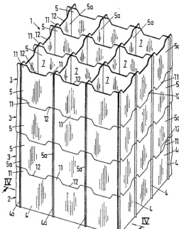
The basic structure of the rack structure for a BWR storage rack looks as follows :
5Q
1112;
!\5
II.!2-~
Lii IL'
rliJ
ljF ¸'
5a
"/1'
jFri, J
rllZ,, ¸ ,
/
./
ia
Fig. 1 Basic structure of the CCI fuel storage racks
SMiRT 16, Washington DC, August 2001 Paper # 1942
DYNAMIC TESTING OF RACKS
The seismic analyses o f the racks requires structural calculational models which have been verified by dynamic testing in air o f
- a test model in reduced scale 1 • 2 - a full rack in full scale
The following figure shows the test arrangement for the reduced scale model o f a rack"
~ ~ l v ~ ~ I I " ' l ' i | l l l
. . . . I l l l l l
I i l l l l I I I I I : l l i i l i ( ,,,I :t I | 1 1 1
" I I I I I
( ~ I l l l l I I I I I I I I I I
, i i - J , , ,
F u e l E l e m e n t
l
S t o r a g e R a c k F ( ~ q I .. I I ! I '1'1 I I 1 i
i
,j , , , , =
~
1 1 I I f~ l
i ' i l J l l J t J , , , , , ,' ~ /| J l , , , , , , /
! , , , , , ~ , ~ I
i , ~ ~ , , , . L J _ _ I
/ j . ~ ~ ' ' /
' L - - L J _ . t ~
--- . ' ~ ~ i
, ' : , . ~ ~ . - . .
. . , - • • • .
..•2)
X = y~13:~ ,..,.~,
~<.~ • Acceleration Measuring Points
5O
j ---"
:
~
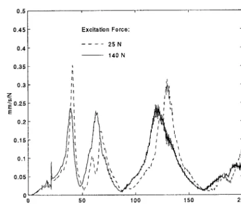
S c r e w e d jFig. 2 Test arrangement for the reduced scale rack with acceleration transducers The response of the excitation of the rack at the top has been done by modal analysis and looks like this •
0.5 , , ' ,
0 . 4 5
0 . 4
0 . 3 5
0 . 3
z
0 , 2 5 E E
0 , 2
0 . 1 5
0.1
0 . 0 5
E x c i t a t i o n F o r c e :
2 5 N
1 4 0 N
I I
I I j , ~k
~, , , _
5 0 1 0 0 1 5 0 2 0 0
F r e q u e n c y ( H z )
The structural damping of the reduced scale rack has been determined to be between 6 and 10 percent of critical damping.
The full scale rack tests were performed on racks with the arrangement of 14 by 17 fuel channels. They were performed in the fabrication shop and on site in the nuclear power plant with mounting of a rotating mass exciter on top of rack. After considering the test results at the fabrication site with a relatively soft floor, it was decided to repeat the tests on a stiffer floor at the plant. Nevertheless, the natural frequencies obtained could be compared by comparative calculations, taking into consideration the relative stiffnesses of the rack feet and the floor. The simple model for correlating the results looked like this :
Stiff beam, representing rack
. . . ~ ~ o t a t i o n a l spring, representing feet and floor
The computation of the actual rack first frequency on the floor in the pool without water was calculated from the tests to be 23.0 Hertz. This compared favorably with the theoretical value of 24.7 Hertz from the structural model obtained from stress analysis. The second main frequency was calculated to be 40.6 Hertz.
CALCULATION MATRIX
As there are various parameters which are not constant, a whole matrix of calculations had to be considered in order to cover all cases of rack configurations which could be subject to a seismic event.
The parameters were the following :
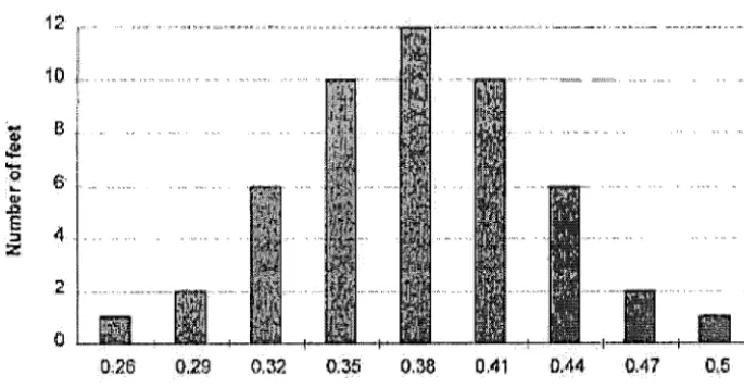
1. Friction factor of the rack feet on the floor. A minimum value would maximize rack sliding, whereas a maximum value would maximize rack tilting. Bounding values of 0.2 and 0.8 were used. For the multi-rack analyses, a random distribution of values for all feet in the middle range around 0.38 was used. The random distribution had a Gaussian representation like this :
t:o ~:
. . . . . . . . . . . . . . . . . . . . . . . . . . . . . . . . . . . . . . . . . . . . . . . ..
...
ii
E~
0;26
:0;29
0;32 0;35 ~0:~38
OAI
D.ii44
0i47..0..!5
Fr,letiOn Factor:
Fig. 4 Distribution of friction factors on the individual feet for the multi-rack analysis
2. Number of tiers. The design provided for the placement of a second tier of racks on top of the lower tier. 3. Fuel loading pattern. The values of fuel elements loaded used in a single rack were empty, partial and full 4. Type of spent fuel. The racks were designed to contain standard fuel assemblies (FA) and consolidated FA
(bundled fuel rods with low decay heat after some years of storage, but with much higher mass per cell) 5. seismic level SSE and OBE
The calculation matrix for the computation of the interesting seismic loadings and displacements is as follows • Table 1 • Calculation Matrix
Calc. No. Friction factor Tier numbers FA Loading FA Type Seismic Level Number of racks
1 0.8 1 full standard SSE 1
2 0.2 1 full standard SSE 1
3 0.8 1 full consolidated SSE 1
4 0.2 1 full consolidated SSE 1
5 0.8 1 + 2 full standard SSE 2
6 0.2 1 empty - SSE 1
7 0.2 1 partial standard SSE 1
1 standard SSE 1
10
0.8 0.2 0.8
partial partial partial
consolidated consolidated
SSE SSE
11 Distribution 1 full consolidated SSE 10
12 0.8 1 full standard OBE 1
13 0.8 1 full consolidated OBE 1
14 0.8 1 + 2 full standard OBE 2
CALCULATIONAL FINITE ELEMENT MODEL
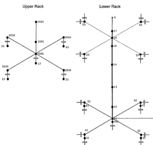
The computational model for the lower and upper tier of racks is shown in the following sketch for a single rack"
Upper Rack Lower Rack
..[_ g ._[_
T
,206
2oo
-l-
20~Oj' ' " ~ , -l-
2 1 ¸ 2E °3°
23-g
L3
3
}
-1-
Fig. 5 The finite element representation of the fuel storage racks
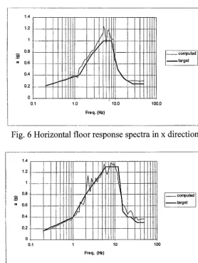
SEISMIC INPUT
The seismic input for the non-linear time history analyses are three accelerograms in the 3 directions, from which one horizontal and one vertical is shown in their spectra representations •
1.0
Freq. (Hz.)
, computed
t a r g e t
1
Fig. 6 Horizontal floor r e s p o n s e spectra in x direction
10.0 100.0
o.1
0
m 0
! I
0.1 1
AA'~ ~, v i
)¢-
/
t
Freq. (Hz)
!i
~:::11
ill
target I
Fig. 7 Vertical floor r e s p o n s e spectra in z direction
DAMPING REPRESENTATION
The viscous damping matrix is represented as follows •
[C] = a [M] + 13 [K] [M] Mass Matrix [K] Stiffness Matrix
The approximation as a function of frequency results in the following function"
i8% 16% 14% 12% 10%
a.a 8%
4°/.
2%
00/° 4 . . .
' i+ 0/
~ ~ ~ ' * - - - - ~ ~ ~ ~
0 5 10 15 20 25 30
Freq. (Hz)
COMPARISON OF SINGLE AND MULTI-RACK ANALYSES
Several single rack analyses have been performed for different loading conditions and extreme values for the friction coefficient. The assessment of the stability of the racks, the displacements and the structural integrity have been based on these calculations.
In order to account for the interaction of all closely spaced rack modules, a whole pool multi rack analysis has also been performed for fully loaded racks with the consolidated fuel assemblies. Randomly distributed friction coefficients have been used in this analysis.
The following table shows the comparison :of the multi-rack analysis results with the corresponding single analysis results (lower single rack fully loaded with consolidated fuel assemblies, frictions 0.2 and 0.8, respectively). It is apparent, that the results of the single rack analyses are conservative with respect to displacements and loadings.
Table 2 Comparison between single rack and multi rack analyses results
Item Description
Gap Size between feet and pool floor Slide between feet and pool floor in x Slide between feet and pool floor in y Displacements relative to pool wall at
the top of the racks in x Displacements relative to pool wall at
the top of the racks in y Normal forces acting on feet Friction forces acting on feet Interaction force FX cell/support plate Interaction force FY cell/support plate Interact. moment MX cell/support plate Interact. moment MY cell/support plate
Dimensions Single Rack Analysis
3.3
Multi Rack Analysis
mm 2.1
mm 20.6 9.5
mm 39.9 13.5
mm 20.4 10.8
mm 39.4 14.5
kN 1275 1156
kN 718.7 555
kN 550.8 690.1
kN 647.2 613.1
kNm 2090 1578
kNm 1518 1460
SUMMARY OF RESULTS
From the 13 single rack load cases analysed with time history analyses, the following peak values can be extracted"
Table 3 Summary of single rack analyses
Max. lift of the supports from the pool floor (mm) Max. slide of the supports in the direction of the pool long side (mm)
Max. slide of the supports in the direction of the pool short side (mm)
Min. distance between top of lower rack and pool wall in the direction of the pool long side (mm)
Min. distance between top of lower rack and pool wall in the direction of the pool short side (mm)
Max. lift off of the upper rack from the lower rack (mm) Max. normal force per foot acting on pool floor (kN) Max. sliding force per foot acting on pool floor (kN)
Standard FA
2.9 15 23 74 64 853 Consolidated FA 3.3 21 40 68 47 1275
Lower + Upper Rack 18 26 30 31 49 16 1886