R E S E A R C H
Open Access
A novel high-frequency encoding algorithm
for image compression
Mohammed M. Siddeq and Marcos A. Rodrigues
*Abstract
In this paper, a new method for image compression is proposed whose quality is demonstrated through accurate 3D reconstruction from 2D images. The method is based on the discrete cosine transform (DCT) together with a high-frequency minimization encoding algorithm at compression stage and a new concurrent binary search algorithm at decompression stage. The proposed compression method consists of five main steps: (1) divide the image into blocks and apply DCT to each block; (2) apply a high-frequency minimization method to the AC-coefficients reducing each block by 2/3 resulting in a minimized array; (3) build a look up table of probability data to enable the recovery of the original high frequencies at decompression stage; (4) apply a delta or differential operator to the list of DC-components; and (5) apply arithmetic encoding to the outputs of steps (2) and (4). At decompression stage, the look up table and the concurrent binary search algorithm are used to reconstruct all high-frequency AC-coefficients while the DC-components are decoded by reversing the arithmetic coding. Finally, the inverse DCT recovers the original image. We tested the technique by compressing and decompressing 2D images including images with structured light patterns for 3D reconstruction. The technique is compared with JPEG and JPEG2000 through 2D and 3D RMSE. Results demonstrate that the proposed compression method is perceptually superior to JPEG with equivalent quality to JPEG2000. Concerning 3D surface reconstruction from images, it is demonstrated that the proposed method is superior to both JPEG and JPEG2000.
Keywords:2D image compression, DCT, High-frequency minimization, Concurrent binary search, 3D surface reconstruction
1 Introduction
Multimedia requirements demand efficient compression techniques for large data files such as image, video, and 3D data. While the relative price of storage has steadily decreased in the past decades, the amount of generated image and video data has increased exponentially. This is more evident on large data repositories such as YouTube and cloud storage. The increased growth in network traffic and storage requirements means that data compression algorithms can have a large impact on data centres concerning bandwidth, physical storage space, and energy usage. This paper proposes an efficient data compression algorithm based on the discrete cosine transform (DCT) together with several novel steps including the minimization of high-frequency components,
a differential process, and a lookup table based search by concurrent binary algorithms at decompression stage.
The DCT has been extensively used [1, 2] in image compression. The image is divided into segments and each segment is then subjected to the transform, creating a series of frequency components that correspond with detail levels of the image. Several forms of encoding are applied to store only the relevant coefficients. The DCT is the basis of the popular JPEG file format, and most video compression methods and multi-media applications [3, 4]. JPEG2000 is based on the discrete wavelet transform (DWT) which is one of the mathematical tools for hier-archically decomposing functions. The wavelet transform is the preferred technique for compressing images at higher compression ratios with higher PSNR values [5, 6]. Its superiority in achieving high compression ratios, error resilience and wide adoption has led to the JPEG2000 ISO standard. The JPEG2000 codec is more efficient than its predecessor JPEG and overcomes many of its * Correspondence:[email protected]
GMPR-Geometric Modelling and Pattern Recognition Research Group, Sheffield Hallam University, Sheffield, UK
drawbacks [7]. It also offers higher flexibility compared to other codes such as region of interest, high dynamic range of intensity values, multi component, lossy and lossless compression, efficient computation, and compres-sion rate control. The robustness of JPEG2000 stems from the DWT which supports multi-resolution representations in both spatial and frequency domains. In addition, the DWT supports progressive image transmission and region of interest coding [8, 9].
To demonstrate the effectiveness of the proposed ap-proach, we focus on compressing 2D image data appropri-ate for 3D reconstruction. This includes 3D reconstruction from structured light images, and 3D reconstruction from multiple viewpoint images. Previously, we have demon-strated that while geometry and connectivity of a 3D mesh can be tackled by several techniques such as high degree polynomial interpolation [10] or partial differential equa-tions [11, 12], the issue of efficient compression of 2D images both for 3D reconstruction and texture mapping has not yet been addressed in a satisfactory manner. More-over, in most applications that share common data, it is necessary to transmit 3D models over the Internet. For example, to share CAD/CAM assets, e-commerce applica-tions, update content for entertainment applicaapplica-tions, or to support collaborative design, analysis, and display of engin-eering, medical, and scientific datasets. Bandwidth imposes hard limits on the amount of data transmission and, together with storage costs, calls for more efficient 3D data compression for exchange over the Internet and other networked environments. Using structured light techniques for 3D reconstruction, surface patches can be compressed as a 2D image together with 3D calibration parameters, transmitted over a network and remotely reconstructed (geometry, connectivity and texture map) at the receiving end with the same resolution as the original data [13, 14].
Related to the techniques proposed in this paper, our previous work on data compression is summarised as follows. Focused on compressing structured light images for 3D reconstruction, Siddeq and Rodrigues [13] proposed a method where a single level DWT is followed by a DCT on the LL sub-band yielding the DC components and the AC-matrix. A second DWT is applied to the DC compo-nents whose second level LL2 sub-band is transformed again by DCT. A matrix minimization algorithm is applied to the AC-matrix and other sub-bands. Compression ratios of up to 98.8% were achieved. In Siddeq and Rodrigues [13], similar transformations are applied to variant arrange-ments of data blocks followed by arithmetic coding. The novel aspect of that paper is at decompression stage, where a parallel sequential search algorithm is proposed and demonstrated. Compression ratios of up to 98.5% were achieved. In Siddeq and Rodrigues [15], a two-level DWT was applied followed by a DCT to generate a
DC-component array and an MA-Matrix (Multi-Array Matrix). The MA-matrix is then partitioned into blocks and a minimization algorithm codes each block followed by arith-metic coding. At decompression stage a new proposed algo-rithm, Sequential-search algorithm is used to estimate the MA-matrix. Compression ratios up to 98.1% were achieved. In Siddeq and Rodrigues [16], compression consists of two level DWT followed by two level DCT. A minimize-matrix-size (MMS) algorithm is applied to the AC-matrix and to the other high frequencies followed by arithmetic coding to the output of previous steps. A novel fast-match-search decompression algorithm is used to reconstruct all high-frequency matrices by computing all compressed data prob-abilities through a binary search algorithm to estimate the data from a look up table. A comparative analysis of various combinations of DWT and DCT block sizes is performed, with compression ratios up to 98%.
In Siddeq and Rodrigues [17], the issue of compressing 3D data geometry, connectivity and texture is addressed through a novel geometry minimization algorithm (GM-al-gorithm) applied to mesh vertices and triangulated faces with arithmetic coding. First, each vertex (x, y, z) coordi-nates are encoded to a single value by the GM-algorithm. Second, triangle faces are encoded by computing the differences between two adjacent vertex locations, which are compressed by arithmetic coding together with texture coordinates. The method was demonstrated on large data sets achieving compression ratios between 87—99% without reduction neither in the number of reconstructed vertices nor triangulated faces. Finally, in Siddeq and Rodrigues [18], work is focused on 3D data only under various formats. The GM-algorithm is used to com-press vertices and triangulated faces, where faces are encoded by computing the differences between two adjacent vertex locations, and then again coded by the GM-Algorithm and arithmetic coding. High compres-sion ratios over 90% were achieved. A comparative analysis of compression ratios is provided with several commonly used 3D file formats showing the advan-tages and effectiveness of the approach.
concurrent fashion. These are described in the follow-ing sections.
This paper is organized as follows. Section 2 intro-duces the DCT and how it is applied over an image by the proposed method. Section 3 describes the high-frequency minimization algorithm and Section 4 describes how such compressed data are recovered through a concurrent binary search algorithm. Section 5 describes experimental results for both 2D image compression followed by 3D reconstruction from 2D structured light images and 3D reconstruction from multiple viewpoint images. Finally, Section 6 summa-rizes and concludes the paper.
2 The discrete cosine transform (DCT)
In the proposed method, the DCT is applied to an image by first dividing the image into non-overlapping n × n blocks (n≥8) and then transformed by DCT to produce de-correlated coefficients. Each block in the frequency domain consists of the following: DC-component at the first location of each block which is a measure of the average value of the samples in the block, and other co-efficients called AC coco-efficients as described in Eq. (1) [2, 6, 19]:
C ið Þ ¼;v a uð Þa vð ÞX
x¼0 n−1 X
y¼0 n−1
f xð ;yÞcos
2xþ1
ð Þuπ
2n
2yþ1
ð Þvπ
2n
ð1Þ wherea uð Þ ¼
ffiffi
1 n
q
; f or u¼0; a uð Þ ¼ ffiffi
2 n
q
; f or u≠0:
The quantization of each block nn can be repre-sented as follows:
Qð Þi;j ¼LðiþjÞ ð2Þ
Where i;j¼1;2;…;n and the quantization factor is an integer L>1. Each nn block is quantized by Eq. (2) using dot-division-matrix which truncates the results. This process removes insignificant coefficients and increases the number of zeroes in each block. The parameter L is used to increase or decrease the value of Q. Thus, image details are reduced or lost as the value of L increases. The range of L is not limited a priori because it depends on the DCT coefficients and image resolution. The next step is to split the DC-components from each quantized block nn by sav-ing those into a new array called DC-Array. Then the
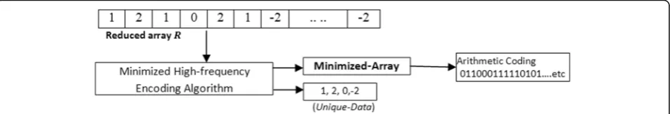
Fig. 2Unique data appearing inRare kept in the header file allowing key recovery
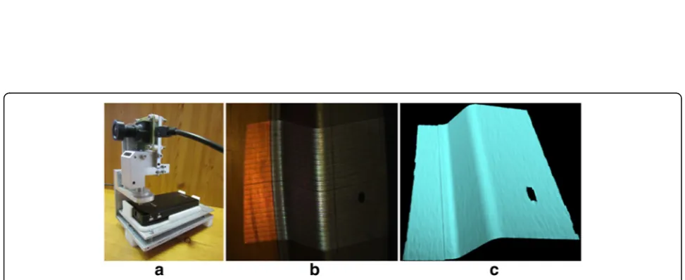
Fig. 4aThe 3D Scanner developed by the GMPR group,b2D BMP picture captured by the camera,c2D image converted into a 3D surface patch
differences between two adjacent values in DC-Array are computed. This differential process generates coef-ficients that are correlated (generally the values are similar as the DC values of adjacent blocks tend to be similar) so their differences are small and more data are repeated. This process facilitates compression by arithmetic coding and is defined as follows.
Di¼Di−Dðiþ1Þ ð3Þ
where i= 1, 2,…,p−1 and p is the size of DC-array. Meanwhile, the remaining AC coefficients (e.g., the 63 AC coefficients for an 88 block) are converted into a one-dimensional array by scanning column-by-column and saved into an AC-matrix. This matrix is subject to a high-frequency minimization algorithm de-scribed next.
3 High-frequency minimization algorithm
TheAC-matrixis transformed by a matrix minimization method involving eliminating zeros and triplet encoding whose output is then subjected to arithmetic coding. Nor-mally, the AC-matrix contains a large number of zeroes with a few nonzero data. Here, we propose a technique to eliminate blocks of zeroes and store blocks of nonzero data into a one-dimensional array. The algorithm starts by partitioning the AC-matrix into non-overlapping blocksn×n (n≥8). Each block is scanned for nonzero data which, if existing, are stored into a reduced array Rand the location of that block is recorded. Otherwise,
the block contains only zeros and is ignored. The algo-rithm is illustrated below.
Once only nonzero data are saved into the reduced array R, a high-frequency minimization encoding is applied further reducing its size by 2/3. This process hinges on defining three key values and multiplying these keys by three adjacent entries inR which are then summed over. The key values K1,K2, andK3are
gener-ated by a key generator algorithm as follows.
M¼1:5 maxð ÞR ð4Þ
K1¼rand 0ð ;1Þ ð5Þ
K2¼K1þMþ F ð6Þ
K3¼F M Kð 1þK2Þ ð7Þ
whereF≥1 is an integer scaling factor. Assuming that N
is the length ofR, i¼1;2;…;N3 is the index of data
in R, and j is the index of encoded minimized array Aj, the following transformation defines the high-frequency minimization encoding:
Aj¼K1RiþK2Riþ1þK3Riþ2 ð8Þ
Each value of R in the triplet summation of Eq. (8) can later be recovered by estimating the key values for that block [13, 20, 21]. However, this problem is underdetermined and extra information is required. This information is kept in the header of the com-pressed file as a string of unique-data appearing in R. Figure 2 illustrates the concept through a numerical example.
Each image has its own high-frequency coefficients. The proposed algorithm computes a set of unique data for the high-frequency coefficients for a given image. Being unique to that image, the set cannot be used to reconstruct the high-frequency coefficients for a different image. Figure 2 shows a set of unique data for the reduced array R. This means that the unique data set will be used at decompression stage to re-construct the array R. The size and contents of the unique data vector are thus, data dependent.
The encoded triplets into arrayAmay contain large number of zeros which can be further encoded through a process proposed in [16]. For example, assume the following encoded minimized array A=[0.5, 0, 0,0, 7.3, 0, 0,0,0,0, −7]. The zero array will be [0,3,0,5,0] where the zeros in red refer to nonzero data existing
at these positions and the numbers in black refer to the number of zeros between two consecutive non-zero data. To increase the compression ratio, the number 5 can be broken up into 3 and 2 to increase data redundancy. Thus, the equivalent zero array would be [0,3,0,3,2,0] and the nonzero array would be [0.5, 7.3, −7].
The final step of compression is arithmetic coding which computes the probability of all data and assigns a range to each data (low and high) to generate streams of compressed bits [6]. The arithmetic coding applied here takes a stream of data and converts into a single floating point value. The output is in the range between zero and Fig. 6Topandbottom rows: the reconstructed 3D surfaces from images FACE1 and FACE2 at various compression ratios
Table 1Proposed image compression and decompression applied to greyscale images (original image size = 1.37 MB)
Image name Block size used by DCT
Factor Compressed image size (KB)
Bit rate/ pixel
2D RMSE
3D RMSE
FACE1 1616 5 34.2 0.024 4.0 1.45
1616 10 18.3 0.012 5.12 2.48
3232 5 20.7 0.014 4.79 2.25
3232 10 11 0.007 5.83 2.36
6464 10 6.4 0.0045 6.65 2.57
FACE2 1616 5 21.98 0.015 2.65 1.11
1616 10 12.25 0.0086 3.32 1.45
3232 5 14.47 0.01 3.12 0.98
one that, when decoded, returns the exact original stream of data.
4 The concurrent binary search decompression algorithm
While the DC-Array can be recovered by a simple addition process, the issue here is how to recover the reduced arrayRthat has been compressed into the min-imized array A. For this purpose, we have devised a new Concurrent Binary Search Algorithm(CBS-Algorithm). The
reverse of the compression algorithm consists of three stages:
1) Decode the DC-components: the first step is to reverse the differential process of Eq. (3) by addition such that the encoded values in DC-array return to their original DC-components. This process takes the last value at position m, and adds it to the previous value, and then the total adds to the next previous value and so on. 2) Decode the Minimized-array using the
CBS-Algorithm: this novel algorithm has been designed to recover the reduced array R from the minimized array A. The compressed data contains information about the three compression keys defined in Eqs. (5–7) and the probability data (unique data) followed by compressed streams of data. The CBS-algorithm picks up in turn each data element from the minimized-array and reconstructs the three keys recovering the tripletRof data through a concurrent binary search illustrated by steps A and B:
A) Initially, the estimated values defined in Unique-Data array (see Fig.2) are set to the same value, that isA1¼B1¼C1;A2¼B2¼C2; A3¼B3¼C3:
The searching algorithm computes all possible combinations of A withK1, B withK2and C with
Table 2Proposed image compression and decompression applied to colour images (original image size = 3.75 MB) Image
name
Block size used by DCT
FactorFfor each layer [Y, Cb, Cr]
Compressed image size (KB)
Bit rate/ pixel
2D RMSE
3D RMSE
WALL 6464 [5,5,5] 14 0.0036 2.4 0.25
6464 [10, 10, 10] 7.6 0.0019 2.8 2.11
6464 [25, 25,25] 5.0 0.001 3.5 0.59
CORNER 3232 [10,10,10] 20 0.0052 5.34 0.14
3232 [20, 20, 20] 10 0.0026 6.7 0.65
6464 [30, 30,30] 5.1 0.0013 8.26 2.08
METAL 3232 [2, 25, 25] 25.2 0.0065 4.19 1.89
3232 [5, 25, 25] 13.4 0.0034 4.48 2.04
6464 [5, 25, 25] 9.8 0.0025 4.73 2.00
K3that yield a result keeping in D-array. As a means
of an example consider that Unique-Data1=[A1A2
A3] , Unique-Data2=[B1B2B3] and Unique-Data3=[
C1C2C3]. Then, according to Eq. (4) these represent
the coded summation, respectively, and the equation is executed 27 times to build theRarray, as de-scribed in Fig.3a. The match indicates that the unique combination of A, B, and C are the original data (i.e., decompressed data) [16].
B)A Binary Search algorithm[22] is used to recover the data and their keys. Our design consists ofk
concurrent binary search algorithms to reconstruct the triplets of original data in theRarray, as shown in Fig. 3b. At each step, each binary search algorithm takes a single compressed data from the minimized-array and compares with the middle element of the D-array. If the values match, then a matching element has been found and its relevant (A, B, and C) returned. Otherwise, if the search is less than the middle element the algorithm is repeated to the left of the middle element or, if the value is greater, to the right. All binary search algorithms are synchronised [16].
3) Combine the DC-components with AC-coefficients: once the reduced arrayRis recovered in step 2, the corresponding high frequency AC-Matrix is re-built by placing the nonzero data in the exact locations defined by the algorithm in Section 3. The DC-components and AC-coefficients are then followed by inverse quantization (dot-multiplication with Eq. (2) Table 3Compression and decompression of 3D images by
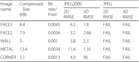
JPEG2000 and JPEG at higher compression ratios Image
name
Compressed ` Size (KB)
Bit rate/ Pixel
JPEG2000 JPEG
2D RMSE
3D RMSE
2D RMSE
3D RMSE
FACE1 6.4 0.0045 6.3 1.8 FAIL FAIL
FACE2 7.9 0.0056 3.2 2.66 FAIL FAIL
WALL 5 0.001 3.8 2.3 FAIL FAIL
METAL 13.4 0.0034 11.6 1.35 FAIL FAIL
CORNER 5.1 0.0013 4.0 90 FAIL FAIL
and the inverse DCT is applied to each blocknn
Eq. (9) below, to recover the original image.
f xð ;yÞ ¼X
The experimental results described here were implemented in MATLAB R2013a and Visual C++ 2008 running on an AMD Quad-Core microprocessor. We describe the results in two parts: first, we apply the compression and decom-pression algorithms to 2D images that contain structured light patterns allowing 3D surface data to be generated from those patterns. The rationale is that a high-quality image compression is required otherwise the resulting 3D structure from the decompressed image will contain appar-ent dissimilarities when compared to the 3D structure obtained from the original (uncompressed) data. We report on these differences in 3D through visualization and stand-ard measures of RMSE-root mean square error. Second, we apply the method to general 2D images (with no structured light patterns) of different sizes and assess their perceived visual quality and RMSE. Additionally, we compare our compression method with JPEG and JPEG2000 through the
visualization of 2D images, 3D surface reconstruction from multiple views and RMSE error measures.
5.1 Results for structured light images and 3D surfaces
3D surface reconstruction was performed with our own software developed within the GMPR group [11, 12, 14]. The justification for introducing 3D reconstruction is that we can make use of a new set of metrics in terms of error measures and perceived quality of the 3D visualization to assess the quality of the compression/ decompression algorithms. The principle of operation of GMPR 3D surface scanning is to project patterns of light onto the target surface whose image is recorded by a camera. The shape of the captured pattern is com-bined with the spatial relationship between the light source and the camera, to determine the 3D position of the surface along the pattern. The main advantages of the method are speed and accuracy; a surface can be scanned from a single 2D image and processed into 3D surface in a few millisec-onds [23].
Figure 4 (left) depicts the GMPR scanner together with an image captured by the camera (middle) which is then converted into a 3D surface and visualized (right). Note that only the portions of the image that contain patterns (stripes) can be converted into 3D; other parts of the image are ignored by the 3D reconstruction algorithms.
Figure 5 shows several test images used to generate 3D surfaces both in greyscale and colour. The top row shows two greyscale face images, FACE1 and FACE2 with size 1.37 MB and dimensions 13921040 pixels. The bottom row shows colour images CORNER, WALL, and METAL with size 3.75 MB and dimension 12801024 pixels. It is important to stress here that the RMSE although useful, is a single measure of error and may not give a clear indication to which reconstruction is `best'. This is so because errors could be concentrated in an area that we perceive as less important in the image, and this is more clearly seen by analysing the 3D surface images at various compression ratios.
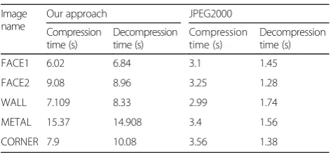
Figure 6 shows a visualization of the decompressed images converted to 3D surfaces using different DCT block sizes (from 1616 to 6464). FACE1 on the top Table 4Execution time of our approach compared with
JPEG2000
FACE1 6.02 6.84 3.1 1.45
FACE2 9.08 8.96 3.25 1.28
WALL 7.109 8.33 2.99 1.74
METAL 15.37 14.908 3.4 1.56
CORNER 7.9 10.08 3.56 1.38
Table 5Proposed image compression and decompression applied to 2D images
Image
Our approach Our Approach JPEG2000 JPEG
Block size used by DCT Compressed image size (KB) Bit rate/Pixel 2D RMSE 2D RMSE 2D RMSE
X-ray 0.588 88 10 1.66E-5 5.0 3.2 11.88
Eye 9 6464 14.2 4.51E-6 4.89 4.1 15.3
Girl 2.25 1616 21.2 2.69E-5 10.48 6.4 21.1
Cell 8.5 6464 9.8 3.26E-6 4.2 2.5 16
row from the left, the first and second 3D surfaces with RMSE of 1.45 and 2.48 are high-quality surfaces compar-able to the original one. The 3D surface with 3D RMSE
2.25 (third image from left) is lower than 2.48 (second image) but its perceived quality is not higher, instead it is lower due to localised errors in less important areas of the face. Figure 6 bottom row shows the decompressed FACE2 images. The 3D surfaces with 3D RMSE of 1.11 and 1.45 represent high-quality surfaces comparable to the original surface, while the other two represent median to low quality with varying degrees of degradation. It is apparent here that because the RMSE algorithm only calculates the differences between valid surfaces points in two surfaces (original and reconstructed from com-pressed data) the dropping or disappearance of some areas on the surface will have a marked effect on the mean error.
Tables 1 and 2 provide a quantitative view of compression concerning 2D structured light images and corresponding 3D surface reconstruction for several different DCT block sizes and quantisation factors. The purpose is to analyse the sensitiveness of the algorithms to both parameters. In Table 1 there is only one value for quantization factorLas these are grey scale images and thus there is only one colour channel to quantise. As expected, it is observed that by doubling the factor, the size of the compressed image is halved. On the other hand, by doubling the block size, the size of the compressed image is only reduced by about a third. It is also observed that no relationship exists concerning block size, factor, and RMSE (both in 2D and 3D). An image that is compressed to double the size of an earlier compression does not mean that its RMSE will be halved compared to the earlier RMSE. The reasons for this have been pointed out above as localised errors in the image will give rise to localised errors in the 3D structure and these do not necessarily correspond to our perception of better or worst.
Table 2 depicts three parameters for quantization factorL, one for each channel as these are colour images. Here again by doubling the factor it is observed a halving of the com-pressed image size. Normally, it would not make sense to have different factor values for different colour channels, but this is a possibility that can be exploited especially in struc-tured light applications where we know that patterns can be projected using a single colour channel (red, green or blue). The same comments above on RMSE also apply here.
Figure 7 depicts the 3D surface images from the de-compressed WALL, CORNER and METAL images. The first image on the left with texture mapping on is for in-formation only. The remaining three shaded images were compressed by varying the DCT block size and the colour channels per data depicted in Table 2. Thus, the first rows of shaded images correspond to the first three entries in Table 2 and so on. The perceived quality of all reconstructed 3D surface images follows a similar pat-tern: as the quantisation factorLis increased, the size of the compressed file decreases with corresponding deteri-oration in quality and this is the expected behaviour.
Table 3 and Fig. 8 describe the compressed and de-compressed results for JPEG and JPEG2000 with com-parison with our approach. Here, we compressed very aggressively and in Table 3 the JPEG algorithm simply failed to compress images at the required ratio with equivalent file sizes as our approach. This is indicated by “FAIL”. An important point to note is that while JPEG2000 can compress to equivalent ratios or file sizes as our algorithm, the decompressed image is not of equivalent quality for the purposes of 3D reconstruction. Figure 8 provides a direct comparison between our ap-proach and JPEG2000 for quality assessment through visualisation of the reconstructed 3D surface. Each file containing structured light patterns was compressed to the same size using our method and JPEG2000. The visualisation clearly indicates that our method is super-ior to JPEG2000 concerning 3D reconstruction in all cases considered both in terms of perceived quality of the reconstruction and absolute RMSE. Additionally, Table 4 shows time execution for our approach com-pared with JPEG2000. The JPEG technique was unable to compress to the required size, for this reason it does not appear on Table 4.
5.2 Results for 2D images
In this section, we report on our approach applied to generic 2D images, that is, images that do not contain structured light patterns as described in the previous section. Table 4 tabulates compression results and com-parison of our approach with the two compression algo-rithms JPEG2000 and JPEG respectively using five
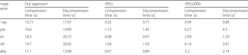
Table 6Execution time of our approach compared with JPEG and JPEG2000
Image
X-ray 13.71 17.47 0.55 0.71 0.49 0.89
Eyes 16.6 19.89 1.15 1.45 6.27 4.3
Girl 18.3 20.75 0.48 0.91 2.99 1.29
Cell 14.7 20.02 1.04 1.43 6.14 2.67
publicly available images with sizes varying from 0.5 to 9 MB. For each image, we used different block sizes, it varies for different images from 8 × 8 to 64 × 64 as depicted in Table 5. Despite the RMSE limitations as an absolute measure of quality, the tabulated values indicate that JPEG has a much higher error than both our tech-nique and JPEG2000. For this reason, and for its per-ceived lower quality it is the least desirable technique.
Figure 9 depicts decompressed images by our ap-proach with a comparison with JPEG2000 and JPEG. One can state that JPEG2000 seems to be the better
technique for general 2D compression as it has a high perceived quality with low RMSE. Our technique is much better than JPEG and at comparable level to JPEG2000 concerning perceived quality, but with slightly higher RMSE. Thus, the results reported in this section demonstrate that our proposed compression method can equally be used as a general 2D compression technique and, as both JPEG and JPEG2000 are widely used in video compression, our technique is also appropriate for video compression. Furthermore, considering the results reported in the previous section, our method is superior
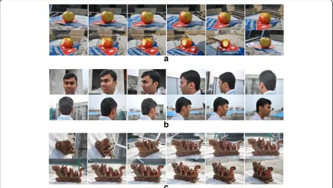
Fig. 10a,bandc: Sample sequence of images“Apple”,“Face”and“Ship”.aApple images: number of image 48 images.bFace images: number of images 28 images.cShip images: number of images 51 images
Table 7Testing with additional images and compared with JPEG and JPEG2000
Image name Our approach JPEG Technique JPEG2000 technique
Compressed size (KB) Bit rate/pixel RMSE Compressed size (KB) Bit rate/pixel RMSE Compressed size (KB) Bit rate/pixel RMSE
Apples 11.78 8.1e-06 5.08 21.2 1.47e-05 10.94 12 8.3e-06 3.03
Bananas 12.44 8.6e-06 4.57 20.8 1.44e-05 10.7 13 9.02e-6 3.66
Billiard_balls_a 19.91 1.38e-06 4.26 23.1 1.6e-05 11.51 20 1.38e-05 2.09
Building 33.5 2.3e-05 5.55 36 2.5e-05 7.24 34 2.36e-05 3.23
Cards_a 49.6 3.4e-05 9.33 54.8 3.8e-05 10.69 50 3.47e-05 7.6
Clips 58.3 4.0e-05 9.56 59.4 4.15e-05 11.23 59.9 4.15e-05 5.67
Coins 32.5 2.25e-05 9.01 33.4 2.31e-05 11.01 33 2.29e-05 6.8
Ducks 16.4 1.14e-05 3.62 22 1.52e-05 10.58 17 1.18e-05 1.92
Flowers 42.3 2.93-05 8.42 43.5 3.02e-05 9.85 43 2.98e-05 5.39
to JPEG and JPEG2000 for 3D reconstruction from struc-tured light images. Also, Table 6 shows the time execution for our approach compared with JPEG and JPEG2000.
Additionally, Table 7 shows our approach tested with additional standard images where each image is of di-mension 1200 × 1200 pixels and uniform size of 4.1 MB. These images are freely available for testing image pro-cessing algorithms from https://testimages.org. While JPEG2000 can compress to approximately the same size as our approach, it is noted that the JPEG technique failed to compress to the same size. It is noted that both compressed size and bit rates are comparable between JPEG2000 and our approach, while our approach pre-sents a slightly higher RMSE.
5.3 Results of 3D reconstruction from multiple viewpoints
Here, we apply our compression techniques to a series of 2D images and usedAutodesk123D Catch software to generate a 3D model from multiple viewpoints. Images are uploaded to the Autodesk server for processing which normally takes a few minutes. The program uses photogrammetric techniques to measure distances between objects yielding a 3D model; i.e., image processing is performed by stitching a plain seam with correct sides together. However, the software may ask the user to select common points on the seam that could not be determined automatically [24, 25].
The objective is to perform a direct comparison between our DCT with high-frequency minimization technique with both JPEG and JPEG2000 on the ability to perform 3D reconstruction from multiple views. Figure 10 shows three series of 2D images for objects“Apple”,“Face”, and “Ship”. First, we verified that these sequences are suitable for 3D reconstruction with Autodesk 123D. Second, we start by compressing each series of images; Table 8 shows their compressed sizes and RMSE measures. Table 9 pre-sents a direct comparison of compression and it is clearly
shown that our approach and JPEG2000 can reach an equivalent maximum compression ratio, while the JPEG technique failed to reach the same state. It is important to stress that while both our technique and JPEG are based on DCT, the fundamental difference in which the DCT is applied in our approach together with the frequency minimization algorithm renders our technique far super-ior to JPEG as shown here.
Therefore, Table 9 shows that JPEG is not appropriate as it fails to compress all images at high compression ratios and is eliminated from the next stage of 3D reconstruction. Concerning JPEG2000, its ability for 3D reconstruction using Autodesk 123D Catch is illustrated in Fig. 11. While the models Ship and Apple are successfully reconstructed, it fails on the Face model which is significantly degraded. In contrast, our technique successfully reconstructs all three models and this is shown in Figs. 12, 13, and 14.
Furthermore, Table 10 shows the execution time for series of images compressed by our approach and com-pared with JPEG2000’s time execution.
6 Conclusions
This paper has presented and demonstrated a new method for image compression and illustrated the qual-ity of compression through 2D and 3D reconstruction, 2D and 3D RMSE and the perceived quality of the visu-alisation. Like JPEG, our proposed method is based on DCT but it is fundamentally different in the way it is ap-plied and incorporates several additional transformations at compression stage such as a differential process, the minimization of high-frequency encoding and concur-rent binary search algorithms at decompression stage. The analysis of the proposed techniques demonstrated in this paper indicates that the most important aspects of the method and their role in providing high-quality image with high compression ratios are as follows:
Table 9Comparison with JPEG and JPEG2000 techniques
Multiple
Our approach JPEG2000 JPEG Our approach JPEG2000 JPEG
Apple 0.929 7.713E-6 9.5 6.58 FAIL 13.93 12.61 FAIL
Face 0.784 1.244E-5 5.1 3.39 FAIL 14.73 12.35 FAIL
Ship 0.916 7.158E-6 14.35 13.81 FAIL 13.67 12.0 FAIL
Table 8Compression sizes and RMSE
Multiple 2D images Total Original BMP file size
Apple 336 52.4 0.929 [40,40,40] 16x16 9.5
Face 200.7 4.55 0.784 [11,30,30] 16 x 16 5.1
1. The DCT can be applied to large block sizes≥8, and the DC-components and AC-coefficients are separated into different matrices by the proposed method and coded separately.
2. Since the AC-coefficients contain a large number of zeros, we applied a new method to eliminate zeros and keep nonzero data. The process keeps significant information while reducing data up to 75%.
3. The minimization of high-frequency encoding algorithm produces a minimized array used to replace each three values from the AC-coefficients by a single floating-point value. This process reduces the coefficients leading to increased compression ratios with faithful decoding.
4. At decompression stage, the concurrent binary search algorithm is the engine for estimating the original data from the minimized array and depends on the organised key values and the
availability of a set of unique data. The efficient C++ implementation allows the concurrent algorithms to recover individual AC-coefficient very efficiently.
5. The key values and unique data are used for coding and decoding an image, without this information images cannot be recovered. This is an important point as a compressed image is equivalent to an encrypted image that can only be reconstructed if the keys are available. This has applications to secure transmission and storage of data.
6. Our proposed image compression algorithm was tested on true colour and YCbCr layered images at high compression ratios.
7. The experiments indicate that the technique can be used for real-time applications such as 3D data objects and video data streaming over the Internet.
Fig. 12a,b3D model for series of Apple images decompressed by our approach (48 images, average 2D RMSE=9.5, total compressed size=929 KB). The compression ratio for the 3D mesh is 99.7% for connectivity and vertices.aAutodesk 123D Catch converts48 Apple images to obtain 3D model.b3D surface details for Apple shows the connections between vertices
The results showed that our approach introduced better image quality at higher compression ratios than JPEG and equivalent perceived quality as JPEG2000. Furthermore, it can more accurately re-construct 3D surfaces at higher compression ratios
than both techniques, i.e., in this respect it is super-ior to JPEG2000. On the other hand, it is more com-plex than both JPEG2000 and JPEG. A summary of the method main advantages and disadvantages is given below:
Fig. 14a,b3D model for series of Ship images decompressed by our approach (51 images, average 2D RMSE=14.35, total compressed size=916 KB). The compression ratio for the 3D mesh is 99.7% for connectivity and vertices.aAutodesk 123D Catch converts 51 Ship images to obtain 3D model.b3D surface derails for Ship shows the connections between vertices
Advantages
○Our proposed method uses different block sizes of 8 × 8 and 16 × 16 leading to higher compression ratios. In contrast, the JPEG algorithm uses only 8 × 8 block size while in JPEG2000, the DWT is applied to the entire image.
○Our proposed algorithm splits the DC values from high-frequency coefficients into two different separate matrices. This step increases the compression ratio. In contrast, JPEG uses zigzag scan to keep the DC-values with high-frequency coefficients. Also, JPEG2000 uses raster scan to encode each sub-band of the DWT.
○The high-frequency minimization method reduces matrix size, increases compression ratio, and encrypts the matrix by using two different keys. This type of algorithm (or similar) is not available neither to JPEG nor JPEG2000. ○The concurrent binary search algorithm for high-frequency matrix reconstruction depends on two different keys (i.e., the same keys used in the compression steps). The use of such keys makes our algorithms suitable for security applications as without the key data cannot be decompressed. ○Concerning 3D reconstruction, our approach can compress some images over 99% without significant degradation of the reconstructed 3D surface. In contrast, images compressed by JPEG or JPEG2000 at the same rate of compression show significant degradation as demonstrated here.
Disadvantages
○The complexity of the compression steps is due to the coding of each three items of data into a single value; for this reason, the time execution for compression is longer than for JPEG and
JPEG2000 and more noticeable for large images. ○The complexity of the decompression algorithm depends on a search method. For this reason, the time execution for decompression is longer than JPEG and JPEG2000.
Future work is focused on efficient implementation of the decoding steps and their application to video com-pression. Research is under way and will be reported in the near future.
Competing interests
The authors declare that they have no competing interests.
Publisher's Note
Springer Nature remains neutral with regard to jurisdictional claims in published maps and institutional affiliations.
Received: 7 December 2016 Accepted: 9 March 2017
References
1. A Al-Haj, Combined DWT-DCT Digital Image Watermarking. Science Publications J. Comput. Sci.3(9), 740–746 (2007)
2. T Suzuki, M Ikehara, Integer fast lapped transforms based on direct-lifting of DCTs for lossy-to-lossless image coding. EURASIP J. Image. Vide. (2013). doi:10.1186/1687-5281-2013-65
3. C Christopoulos, J Askelof, M Larsson, Efficient methods for encoding regions of interest in the upcoming JPEG 2000 still image coding standard. IEEE Signal Proc. Let.7, 9 (2000)
4. IEG Richardson,Video Codec Design(Wiley, 2002) Books supplied direct from Wiley.com
5. G Sadashivappa, KVS Ananda Babu, PERFORMANCE ANALYSIS OF IMAGE CODING USING WAVELETS. IJCSNS International Journal of Computer Science and Network Security8, 10 (2002)
6. K Sayood,Introduction to Data Compression, 2nd edn. (Academic Press, Morgan Kaufman Publishers, San Francisco, 2000)
7. S Esakkirajan, T Veerakumar, V SenthilMurugan, P Navaneethan,Image Compression Using Multiwavelet and Multi-Stage Vector Quantization. International Journal of Signal Processing Vol. 4, No.4, WASET, 2008 8. RC Gonzalez, RE Woods,Digital Image Processing(AddisonWesley publishing
company, United States of America, 2001)
9. T Acharya, PS Tsai,JPEG2000 Standard for Image Compression: Concepts, Algorithms and VLSI Architectures(John Wiley & Sons, New York, 2005) 10. M Rodrigues, A Robinson, A Osman, Efficient 3D data compression through
parameterization of free-form surface patches, inSignal Process and Multimedia Applications (SIGMAP), Proceedings of the 2010 International Conference on IEEE, 2010, pp. 130–135
11. M Rodrigues, A Osman, A Robinson, Partial differential equations for 3D data compression and reconstruction. Journal Advances in Dynamical Systems and Applications12(3), 371–378 (2013a). 2004
12. M Rodrigues, M Kormann, C Schuhler, P Tomek, Robot trajectory planning using OLP and structured light 3D machine vision, inLecture notes in Computer Science Part II. LCNS, 8034 (8034)(Springer, Heidelberg, 2013b), pp. 244–253 13. MM Siddeq, MA Rodrigues,A New 2D Image Compression Technique for 3D Surface Reconstruction. 18th International Conference on Circuits, Systems, Communications and Computers, Santorin Island, Greece, 2014, pp. 379–386 14. M Rodrigues, M Kormann, C Schuhler, P Tomek, Structured light techniques for
3D surface reconstruction in robotic tasks, inAdvances in Intelligent Systems and Computing, ed. by J KACPRZYK (Springer, Heidelberg, 2013c), pp. 805–814 15. MM Siddeq, M RODRIGUES, Applied sequential-search algorithm for
compression-encryption of high-resolution structured light 3D data, in MCCSIS: Multiconference on Computer Science and Information Systems 2015, ed. by K Blashki, Y Xiao (IADIS Press, Gran Canaria, 2015a), pp. 195–202 16. MM Siddeq, M Rodrigues, A novel 2D image compression algorithm based
on two levels DWT and DCT transforms with enhanced minimize-matrix-size algorithm for high resolution structured light 3D surface reconstruction. 3D Res.6(3), 26 (2015b). doi:10.1007/s13319-015-0055-6
17. MM Siddeq, M Rodrigues. Novel 3D compression methods for geometry, connectivity and texture.3D Research.7, 13 (2016a).
18. MM Siddeq, M Rodrigues, 3D Point Cloud Data and Triangle Face Compression by a Novel Geometry Minimization Algorithm and Comparison with other 3D Formats. Proceedings of the international conference on computational methods3, 379–394 (2016b)
19. N Ahmed, T Natarajan, KR Rao. Discrete cosine transforms, IEEE Transactions. Computer. vol. C-23, pp. 90–93 (1974).
Table 10Execution time of our approach compared with JPEG2000
Apple 1900 2096 201.36 81.6
Face 1050 1160 199.7 151.01
20. MM Siddeqand, G Al-Khafaji, Applied Minimize-Matrix-Size Algorithm on the Transformed images by DCT and DWT used for image Compression. Int. J. Comput. Appl.70, 15 (2013)
21. MM Siddeqand, MA Rodrigues, A novel image compression algorithm for high resolution 3D reconstruction. 3D Research Springer5(2), (2014b). doi:10.1007/s13319-014-0007-6
22. D Knuth,Sorting and Searching. Section 6.2.1: Searching an ordered table, the art of computer programming 3, 3rd edn. (Addison-Wesley, 1997), pp. 409–426. ISBN 0-201-89685-0
23. M Rodrigues, M Kormann, C Schuhler, P Tomek, An intelligent real time 3D vision system for robotic welding tasks, inMechatronics and its applications (IEEE Xplore, 2013d), pp. 1–6
24. Autodesk 123D, https://en.wikipedia.org/wiki/Autodesk_123D, Accessed May 2016
25. 123D Catch, http://www.123dapp.com/howto/catch, Accessed May 2016
Submit your manuscript to a
journal and benefi t from:
7Convenient online submission
7Rigorous peer review
7Immediate publication on acceptance
7Open access: articles freely available online
7High visibility within the fi eld
7Retaining the copyright to your article