R E S E A R C H
Open Access
Layered spatial modulation
Salim Abdelkareem Alkhawaldeh
Abstract
In this paper, we propose a layered spatial modulation (L-SM) scheme that combines a multi-layered coding scheme with the spatial modulation. At each antenna selection, the number of active transmit antennas equals the number of layers. The proposed L-SM scheme maximizes the diversity order and coding gain at each antenna selection. The exact pairwise and upper bound bit error probabilities are derived. Several examples of different spatial modulation schemes and the proposed L-SM scheme are simulated with the same number of transmit antennas and same spectral efficiency. As expected, the proposed L-SM scheme satisfies significant increase in the performance compared to all existing spatial modulation schemes.
Keywords:MIMO, Diversity, Spatial multiplexing, Layered spatial modulation, STBC, SM, L-SM
1 Introduction
Significant improvements in the bandwidth efficiency and notable reduction in the probability of error can be ob-tained by using multiple input multiple output (MIMO) technology [1,2]. This technology uses multiple transmit and multiple receive antennas where space and time diver-sities and spatial multiplexing are applied. Several space-time trellis and block coding schemes that improve the diversity and coding gains were proposed [3–9]. On the other hand, a number of coding schemes were intro-duced to improve the spatial multiplexing gain [10–17]. All the above schemes use more than one transmit an-tenna in the same time. Simultaneous activation of multiple transmit antennas causes the channel inter-ference. To avoid this problem, spatial modulation (SM) scheme was presented [18, 19]. This scheme uses one transmit antenna at each time period depending on the first group of input bits. The second group of bits is used to determine which symbol is selected from the constella-tion set. Unfortunately, this scheme needs large number of transmit antennas to increase the spectral efficiency of wireless system. To reduce the number of transmit anten-nas, generalized spatial modulation scheme was proposed [20]. This scheme uses more than one transmit antenna at each time period. However, the transmit diversity is not exploited in this scheme which yields significant degrad-ation in the performance. To overcome this problem, a
scheme that combines spatial modulation and space-time block coding (STBC) referred as STBC-SM was proposed [21]. This scheme takes the advantages of both spatial modulation and space-time block coding. Also, it maxi-mizes the diversity order and multiplexing gain. This scheme suffers from degradation of the spectral efficiency offered by the spatial dimension compared with the con-ventional spatial modulation. To improve the spectral effi-ciency, high-rate STBC-SM (H-STBC-SM) scheme and spatial modulation STBC scheme with cyclic structure (STBC-CSM) were introduced [22, 23]. The number of codewords provided by these schemes is twice the number
of codewords provided by the STBC-SM in [21]. The
transmit diversity order achieved by both schemes is equal to two. However, the H-STBC-SM suffers from small deg-radation in the performance. At the same spectral effi-ciency and with transmit antennas less than those of the STBC-SM scheme, the performance of STBC-CSM
ap-proaches that of the STBC-SM. The authors in [24]
proposed the complex interleaved orthogonal design SM with the high degree of spatial modulation (CIOD-SM-H). The spectral efficiency of this scheme is as that of the H-STBC-SM scheme, and its performance is less than that of the STBC-SM. To further increase the spectral efficiency and the performance, cyclic temporally and spatially
modu-lated STBC (STBC-TSM) scheme was proposed [25]. In
this scheme, Alamouti STBC is rotated over four symbol periods to ensure a transmit diversity order of 2.
In this paper, we propose a layered spatial modulation (L-SM) scheme that avoids large number of transmit
Correspondence:[email protected];[email protected] Communication Engineering Department, Faculty of Engineering Technology, Albalqa Applied University, Amman, Jordan
antennas and provides high spectral efficiency. The pro-posed L-SM scheme achieves significant improvement in the performance compared to that of the all above spatial modulation schemes. The proposed L-SM scheme is based on a multi-layered coding scheme combined with the spatial modulation scheme in [18,19]. At each antenna selection, the proposed L-SM scheme is used with transmit diversity order equals the number of active transmit antennas and maximum coding gain based on specific codeword matrices. The number of layers of the proposed scheme is equal to the number of active trans-mit antennas at each antenna selection.
The exact pairwise and upper bound bit error prob-abilities of the proposed L-SM scheme are derived. Simulation results are demonstrated with several exam-ples of the proposed L-SM scheme and recent spatial modulation schemes combined with STBC. All schemes are compared with the same number of transmit anten-nas and comparable spectral efficiency. These results show that the proposed L-SM scheme significantly out-performs all other spatial modulation schemes.
This paper is organized as follows: In Section 2, the methods that we used are presented. Conventional spatial modulation scheme is presented in Section 3. In Section 4, we propose the L-SM scheme. We derive the pairwise and bit error probabilities of the proposed L-SM scheme in Section 5. In Section 6, numerical re-sults of the proposed L-SM and different spatial modula-tion schemes are demonstrated. Finally, the conclusions of this paper are inserted in Section7.
2 Methods
The proposed L-SM scheme is a combination of a multi-layered coding scheme and the spatial modulation. The codeword of the multi-layered coding scheme contains a number of layers with the same number of active transmit antennas. A number of phase shifts are inserted in the codeword among the layers and symbols to maximize the diversity and coding gains. When all transmit antennas are active, one codeword is transmitted over one codeword period. When the total number of transmit antennas is greater than or equals twice the number of active transmit antennas, two codewords are transmitted from different
active transmit antennas over two different codeword pe-riods at each antenna selection case. Several examples of the proposed L-SM and the state-of-the-art schemes are simulated using Matlab software. The channel is modeled by using the Monte Carlo method. The schemes are com-pared to each other with the same number of transmit and receive antennas and same spectral efficiency.
3 Conventional spatial modulation scheme
The SM scheme in [18, 19] is described in this section as shown in Fig.1. This scheme uses two groups of bits. The first group of k bits is used to select one active transmit antenna i out of Nall antennas at each time period, and the second group of ubits is used to select the symbol cfrom the constellation set that has 2u ele-ments. This results in transmission rate of (k + u) bits per channel use. The advantage of this approach is that it avoids the problem of inter-channel interference.
The signal at receive antennajcan be written as
yj¼
ffiffiffiffiffi
Es
p
ajiciþvj ð1Þ
whereEsis the average symbol energy,ciis the symbolc
transmitted from antennai, and aji is the path gain
be-tween transmit antennai and receive antennaj. It is as-sumed that the path gains are samples of a zero mean complex Gaussian random variable with variance of 0.5 per dimension. The additive noise vj at the receive
an-tenna jis assumed to be independent samples of a zero mean complex Gaussian random variable with variance ofN0/2 per dimension.
The exact pairwise error probability of transmitting ci
and deciding~c~
i is given by [20]
Pr ci→~c~i
¼I N0
N0þN0~ ðNr;NrÞ i≠ ~i; i
¼1;2;⋯;Nt;~i¼1;2;⋯;Nt ð2Þ
where N~0¼N0þEsjcj2þEsj~cj2 and Ix(w1,w2) is the regularized beta function given by
Ixðw1;w2Þ ¼
1
R wð 1;w2Þ Z x
t¼0t
w1−1
ð Þð1−tÞðw2−1Þ
dt ð3Þ
with
R wð 1;w2Þ ¼
The bit error probability of spatial modulation scheme is given by
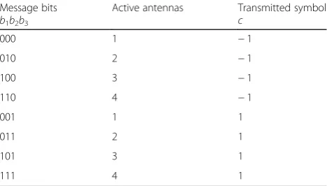
As an example of this scheme is to apply 3 bits per channel use. The first 2 bits are used to select the active transmit antenna out of four antennas, and the third bit is used to select the symbol from the binary phase shift keying (BPSK) constellation set. The transmission and encoding of this example is shown in Table1.
4 Proposed L-SM scheme
4.1 Proposed multi-layered coding scheme without spatial modulation
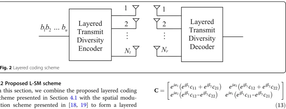
In this subsection, we present a multi-layered coding scheme that maximizes the diversity order and spatial multiplexing gain as shown in Fig.2.
In this scheme, multi layers with the same number of transmit antennas are applied. Each layer contains a num-ber of symbols. The received signal matrix is given as
Y¼
where V is Nr×Nt noise matrix at the receive antennas
whose entries are independent samples of a zero mean complex Gaussian random variable with variance ofN0/2 per dimension. A is Nr×Ntchannel matrix whose entry
ajiis the path gain between transmit antennaiand receive
antennaj, and it is given as
It is assumed that the path gains inAare samples of a zero mean complex Gaussian random variable with
vari-ance of 0.5 per dimension. In (6), C is the codeword
matrix given by
among transmitted symbols and layers, respectively. It is worthy of noting that this scheme provides spectral effi-ciency ofNtsymbols per channel use.
The upper bound of the average probability of codeword matrixCmand the decoder decidedCnis given in [13] as
denotes Hermitian transpose. This result was derived by using the Chernoff’s upper bound [26].
In the case of high signal to noise ratio, (11) can be writ-ten as
values of matrixR, respectively.
The angles α1;⋯;αNt;β1;⋯;βNt have to be chosen to
increase the upper bound of (11). This can be obtained by maximizing the rankrto becomeNtand the product
of eigenvalues (λ1λ2⋯λr) ofR.
It is worthy of noting that this coding scheme achieves
diversity order of Nt×Nr and maximum coding gain
ðλ1λ2⋯λNtÞ
1
Nt under specific values ofα1;⋯;αN
t;β1;⋯;βNt.
Table 1The transmission and encoding of SM scheme with
3 bits/channel use, four transmit antennas, and BPSK modulation
4.2 Proposed L-SM scheme
In this section, we combine the proposed layered coding scheme presented in Section4.1 with the spatial modu-lation scheme presented in [18, 19] to form a layered spatial modulation (L-SM) scheme. Assume that the total number of antennas = Nalland the number of ac-tive transmit antennas at each antenna selection =Nt. In
Section4.1,Nall=Ntand one codeword matrix is
trans-mitted over Nt symbol periods (one codeword period)
with diversity order equals Nt×Nr. In this case, there is
no antenna selection and the proposed scheme uses N2t
symbols perNtchannel use. ForNall≥2Nt, two different
codewords are transmitted from different active transmit antennas over two different codeword periods at each antenna selection case. Depending on the antenna selec-tion case, each codeword is transmitted circularly from Nt active antennas along the total number of transmit
antennas. This produces N¼ðNall2N−Nall!tÞ!Nt!þNall antenna
selections and the number of bits related to these selec-tions =k= log2N. The proposed L-SM scheme achieves diversity order of Nt×Nr and maximum coding gain at
each case of the antenna selections. Since each code-word contains N2
t symbols, the proposed L-SM scheme
uses ðkbitsþ2N2t symbolsÞ per 2Ntchannel use which
is equivalent toð k
2Nt bitsþNtsymbolsÞ per channel use.
Note that Nt symbols =Ntlog2M bits. This yields ð k
2NtþNt log2MÞbits per channel use. For the proposed
L-SM scheme, the received signal matrix over the two codeword periods is sent to the maximum likelihood de-coder to estimate the kbits (b1, b2,…, bk) related to
an-tenna selections and the 2N2t log2M bits related to the
symbols in the two codeword matrices. Two different examples are introduced to explain the concept of the L-SM scheme.
Example 1 We consider the proposed scheme with Nall= Nt= 2. In this case, there is no antenna selection.
Therefore, one codeword with two layers is transmitted from two antennas over one codeword period of time. Assume that the symbolsc11and c12are related to layer 1 and the symbols c21 and c22 are related to layer 2. According to (8), (9), and (10), the transmitted codeword matrixCof this example is given by
C¼ ejα1 ejβ1c11þejβ2c21
ejα2 ejβ1c
12þejβ2c22
ejα2 ejβ1c12−ejβ2c 22
ejα1 ejβ1c11−ejβ2c 21
" #
ð13Þ
The spectral efficiency of this case is equal to 2 sym-bols/s/Hz = (2 log2M) bits/s/Hz. For the case of BPSK modulation, we assume thatα1=β1= 0 as reference. The phase shifts α2and β2have to be chosen to increase the upper bound of (11). This can be obtained by maximizing the rankrand the product of eigenvalues (λ1λ2) ofR. A rank rof 2 and maximum product of eigenvalues (λ1λ2) occur whenα2¼β2¼π2. For the case of quadrature phase
shift keying (QPSK) modulation, α1=β1= 0, α2¼π6, and
β2¼π4 and the spectral efficiency = 4 bits/s/Hz. For the
case of 8-QAM modulation, α1=β1= 0, α2= 0.21π, and β2¼3π
16 and the spectral efficiency = 6 bits/s/Hz.
For the case of 16-QAM modulation,α1=β1= 0,α2= 0.1π, andβ2¼π4and the spectral efficiency = 8 bits/s/Hz.
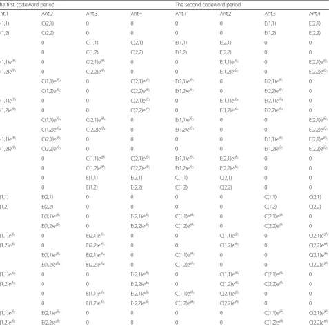
Example 2 We consider the proposed L-SM scheme withNall=4,Nt= 2 and 2 transmitted codewordsCand
E. The transmission approach of this example is
demon-strated in Table 2. Note that the two codewords are
transmitted from different active transmit antennas over two different codeword periods at each antenna selec-tion case. The rotaselec-tion of the two codeword matrices is different than that in [21–25]. The number of antenna selections N¼ 24!
ð4−2Þ!2!þ4¼16 as shown in Table 2and
k= 4. For BPSK, QPSK, 8-QAM, and 16-QAM
modula-tion, the anglesα1, β1, α2, and β2are the same as those in Example 1 whereas the angles θ1, θ2, θ3, θ4, and θ5 are selected to maximize the diversity order to 2Nrand
multiplexing gain and they are equal to12π;2π 12;
4π 12;
5π 12;and 3π
12, respectively. The spectral efficiency of this example
=ð2Nk
t bitsþNtsymbolsÞper channel use = (1 + 2log2M)
bits/s/Hz.
5 Performance analysis of the proposed L-SM scheme
to codeword matricesCmandCptransmitted from two
dif-ferent active antenna combinations over difdif-ferent symbol periods through two codeword periods are given by
Ym ¼
ffiffiffiffiffiffi
Es
Nt
r
AlCmejθlþV1 ð14Þ
Yp ¼
ffiffiffiffiffiffi
Es
Nt
r
AfCpejθf þV2 ð15Þ
where the active channel matricesAlandAfand the
an-glesθlandθfare related to active antenna combinations
landfwhich are different in all antenna elements.
Define matricesG(b1,b2,…,bk,Cm) andG(b1,b2,…,bk,Cp)
as
Gðb1;b2;…;bk;CmÞ ¼Ym−
ffiffiffiffiffiffi
Es
Nt
r
AlCmejθl ¼V1 ð16Þ
G b1;b2;…;bk;Cp
¼Yp−
ffiffiffiffiffiffi
Es
Nt
r
AfCpejθf ¼V2 ð17Þ
G ~b1;~b2;…;~bk;Cn
¼Ym−
ffiffiffiffiffiffi
Es
Nt
r
A~lCnejθ~l ð18Þ
Table 2The transmission and encoding of the proposed L-SM scheme withNall= 4,Nt= 2, and (1 + 2log2M) bits/s/Hz
The first codeword period The second codeword period
Ant.1 Ant.2 Ant.3 Ant.4 Ant.1 Ant.2 Ant.3 Ant.4
C(1,1) C(2,1) 0 0 0 0 E(1,1) E(2,1)
C(1,2) C(2,2) 0 0 0 0 E(1,2) E(2,2)
0 0 C(1,1) C(2,1) E(1,1) E(2,1) 0 0
0 0 C(1,2) C(2,2) E(1,2) E(2,2) 0 0
C(1,1)ejθ1 0 C(2,1)ejθ1 0 0 E(1,1)ejθ2 0 E(2,1)ejθ2
C(1,2)ejθ1 0 C(2,2)ejθ1 0 0 E(1,2)ejθ2 0 E(2,2)ejθ2
0 C(1,1)ejθ2 0 C(2,1)ejθ2 E(1,1)ejθ1 0 E(2,1)ejθ1 0
0 C(1,2)ejθ2 0 C(2,2)ejθ2 E(1,2)ejθ1 0 E(2,2)ejθ1 0
C(1,1)ejθ3 0 0 C(2,1)ejθ3 0 E(1,1)ejθ4 E(2,1)ejθ4 0
C(1,2)ejθ3 0 0 C(2,2)ejθ3 0 E(1,2)ejθ4 E(2,2)ejθ4 0
0 C(1,1)ejθ4 C(2,1)ejθ4 0 E(1,1)ejθ3 0 0 E(2,1)ejθ3
0 C(1,2)ejθ4 C(2,2)ejθ4 0 E(1,2)ejθ3 0 0 E(2,2)ejθ3
C(1,1)ejθ5 C(2,1)ejθ5 0 0 0 0 E(1,1)ejθ5 E(2,1)ejθ5
C(1,2)ejθ5 C(2,2)ejθ5 0 0 0 0 E(1,2)ejθ5 E(2,2)ejθ5
0 0 C(1,1)ejθ5 C(2,1)ejθ5 E(1,1)ejθ5 E(2,1)ejθ5 0 0
0 0 C(1,2)ejθ5 C(2,2)ejθ5 E(1,2)ejθ5 E(2,2)ejθ5 0 0
0 0 E(1,1) E(2,1) C(1,1) C(2,1) 0 0
0 0 E(1,2) E(2,2) C(1,2) C(2,2) 0 0
E(1,1) E(2,1) 0 0 0 0 C(1,1) C(2,1)
E(1,2) E(2,2) 0 0 0 0 C(1,2) C(2,2)
0 E(1,1)ejθ2 0 E(2,1)ejθ2 C(1,1)ejθ1 0 C(2,1)ejθ1 0
0 E(1,2)ejθ2 0 E(2,2)ejθ2 C(1,2)ejθ1 0 C(2,2)ejθ1 0
E(1,1)ejθ1 0 E(2,1)ejθ1 0 0 C(1,1)ejθ2 0 C(2,1)ejθ2
E(1,2)ejθ1 0 E(2,2)ejθ1 0 0 C(1,2)ejθ2 0 C(2,2)ejθ2
0 E(1,1)ejθ4 E(2,1)ejθ4 0 C(1,1)ejθ3 0 0 C(2,1)ejθ3
0 E(1,2)ejθ4 E(2,2)ejθ4 0 C(1,2)ejθ3 0 0 C(2,2)ejθ3
E(1,1)ejθ3 0 0 E(2,1)ejθ3 0 C(1,1)ejθ4 C(2,1)ejθ4 0
E(1,2)ejθ3 0 0 E(2,2)ejθ3 0 C(1,2)ejθ4 C(2,2)ejθ4 0
0 0 E(1,1)ejθ5 E(2,1)ejθ5 C(1,1)ejθ5 C(2,1)ejθ5 0 0
0 0 E(1,2)ejθ5 E(2,2)ejθ5 C(1,2)ejθ5 C(2,2)ejθ5 0 0
E(1,1)ejθ5 E(2,1)ejθ5 0 0 0 0 C(1,1)ejθ5 C(2,1)ejθ5
G ~b1;~b2;…;~bk;Cq
where the subscript F denotes the Frobenius norm of
the matrix.
where the operation ./ is Hadamard division (element by element of the numerator and denominator matrices).
kDðb1;b2;…;bk;CmÞk2F , kDðb1;b2;…;bk;CpÞk2F ,
central chi-square random variables with 2Nr degrees of
freedom. By using the approach in [20], the pairwise error probability can be obtained as
Pr b1;b2;…;bk;Cm;Cp
By using the upper bound presented in [27], the aver-age probability of bit error is given by
Pb≤ X
b1;…;bk;Cm;Cp X
~ b1;…;~bk;Cn;Cq
Ne b1;…;bk;Cm;Cp;~b1;…;~bk;Cn;Cq
kþv ð Þ2kþv
I N0 2N0þz1
N2t Nr;Nr
ð Þ þI N0 2N0þz2
N2t ðNr;NrÞ 0
@
1 A
ð38Þ
6 Numerical results and comparisons
In this section, we compare the performance of the pro-posed L-SM scheme with the spatial modulation schemes: SM [18, 19], STBC-SM [21], STBC-CSM [23],
and STBC-TSM [25] with the same number of antennas
and same spectral efficiency.
Figure 3 shows the bit error probability of the pro-posed L-SM scheme with two layers compared to SM scheme [18, 19] as a function of Eb/N0where Ebis the
bit energy. The proposed L-SM and SM schemes are equipped with two transmit and two receive antennas.
For the proposed L-SM scheme Nall=Nt= 2 and the
codeword is transmitted over one codeword period with-out any antenna selection. QPSK and 8-QAM modula-tion are used for the proposed L-SM and SM schemes, respectively. This yields spectral efficiency of 4 bits/s/Hz for both of them. Example 1 in Section 4.2explains the
0 3 6 9 12 15
10-5 10-4 10-3 10-2 10-1 100
Eb/N0 (dB)
r
or
r
e
ti
b
f
o
yti
li
b
a
b
or
P
SM [18,19], Nall=2, 8-QAM, 4 bits/s/Hz Proposed L-SM, Nall=Nt=2, QPSK, 4 bits/s/Hz
Fig. 3Performance comparison of the SM and proposed L-SM schemes withNr= 2 for 4 bits/s/Hz
0 4 8 12 16 20 24
10-6 10-5 10-4 10-3 10-2 10-1 100
Eb/N0 (dB)
r
or
r
e
ti
b
f
o
yti
li
b
a
b
or
P STBC-CSM [23], Nall=5, Nt=2, BPSK, 3 bits/s/Hz
STBC-SM [21], Nall=4, Nt=2, QPSK, 3 bits/s/Hz STBC-TSM [25], Nall=4, Nt=2, BPSK, 3 bits/s/Hz Proposed L-SM, Nall=4, Nt=2, BPSK, 3 bits/s/Hz
proposed scheme for this case. As can be observed from the figure, the proposed scheme significantly outper-forms the SM scheme.
In Figs. 4 and 5, the performance of the proposed
L-SM, STBC-SM, STBC-CSM and STBC-TSM schemes is presented for Nr= 1 and Nr= 2. All these schemes
ex-cept STBC-CSM are equipped with four transmit anten-nas, and the SM-CSM scheme is equipped with five transmit antennas. The number of active transmit anten-nas of all these schemes is equal to 2. To achieve spec-tral efficiency of 3 bits/s/Hz for all schemes, BPSK modulation is used for the proposed L-SM, STBC-CSM, and STBC-TSM schemes and QPSK is used for
STBC-SM scheme. The proposed L-SM scheme in this case is explained by example 2 of Section 4.2. In both figures, significant improvement in the performance of the proposed L-SM scheme is achieved compared to that of the all other schemes.
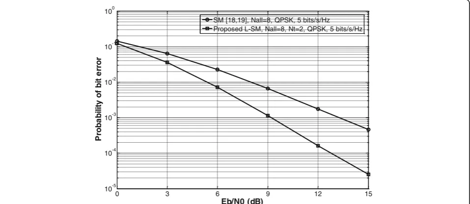
Figure6further compares the performance of the pro-posed L-SM scheme with SM scheme. Both schemes use eight transmit and two receive antennas. The proposed L-SM scheme uses two active transmit antennas and QPSK modulation. The total number of antenna selec-tions N¼ 28!
ð8−2Þ!2!þ8¼64 , but in this example, we use only 16 antenna selections to producek= 4 which yields spectral efficiency of 5 bits/s/Hz. The SM scheme uses
0 3 6 9 12
10-6 10-5 10-4 10-3 10-2 10-1
Eb/N0 (dB)
r
or
r
e
ti
b
f
o
yti
li
b
a
b
or
P STBC-CSM [23], Nall=5, Nt=2, BPSK, 3 bits/s/Hz
STBC-SM [21], Nall=4, Nt=2, QPSK, 3 bits/s/Hz STBC-TSM [25], Nall=4, Nt=2, BPSK, 3 bits/s/Hz Proposed L-SM, Nall=4, Nt=2, BPSK, 3 bits/s/Hz
Fig. 5Performance comparison of STBC-CSM, STBC-SM, STBC-TSM, and proposed L-SM schemes withNr= 2 for 3 bits/s/Hz
0 3 6 9 12 15
10-5 10-4 10-3 10-2 10-1 100
Eb/N0 (dB)
r
or
r
e
ti
b
f
o
yti
li
b
a
b
or
P
SM [18,19], Nall=8, QPSK, 5 bits/s/Hz Proposed L-SM, Nall=8, Nt=2, QPSK, 5 bits/s/Hz
QPSK modulation to satisfy the same spectral efficiency of 5 bits/s/Hz. As expected, similar behavior as in the case of Fig.3is observed.
Note that the generalized spatial modulation scheme in [20] uses more than one active transmit antenna at each time period to increase the spectral efficiency. The performance of this scheme is slightly smaller than the performance of the spatial modulation scheme in [18, 19] with the same spectral efficiency as explained in [20]. Therefore, no need to compare this scheme with our scheme since our scheme significantly outperforms the spatial modulation scheme in [18,19]. Also, no need
to compare our scheme with the H-STBC-SM [22] and
CIOD-SM-H [24] schemes because their performance is
less than that of the STBC-CSM [23] and STBC-TSM
[25] schemes with the same transmit antennas and same spectral efficiency as can be shown in [23,25].
7 Conclusions
We have proposed L-SM scheme with high performance compared to all existing spatial modulation schemes. The proposed L-SM scheme uses a number of layers with the same number of active transmit antennas. At each an-tenna selection, the proposed L-SM scheme maximizes the diversity and coding gains. The performance of the proposed L-SM scheme was analyzed. Numerical results of the proposed L-SM and different spatial modulation schemes were presented. Significant improvement in the performance of the proposed L-SM scheme is achieved compared to that of the other schemes.
Abbreviations
BPSK:Binary phase shift keying; CIOD-SM-H: Complex interleaved orthogonal design SM with the high degree of spatial modulation;Eb/N0: Bit energy to
noise ratio; H-STBC-SM: High-rate space-time block coded spatial modulation; L-SM: Layered spatial modulation; MIMO: Multiple input multiple output; M-QAM: M-ary quadrature amplitude modulation; QPSK: Quadrature phase shift keying; SM: Spatial modulation; STBC: Space-time block coding; STBC-CSM: Spatial modulation space-time block coding scheme with cyclic structure; STBC-SM: Space-time block coded spatial modulation; STBC-TSTBC-SM: Cyclic temporally and spatially modulated space-time block coding
Authors’contributions
All contributions are from the sole author SA. The author read and approved the final manuscript.
Competing interests
The author declares that he has no competing interests.
Publisher’s Note
Springer Nature remains neutral with regard to jurisdictional claims in published maps and institutional affiliations.
Received: 25 April 2018 Accepted: 18 September 2018
References
1. G. Foshini, M. Gans, On the limits of wireless communications in a fading environment when using multiple antennas. Wireless Personal Communications6(3), 311–335 (1998)
2. E. Telatar, Capacity of multi-antenna Gaussian channels. Eur Trans Telecom 10(6), 585–595 (1999)
3. V. Tarokh, N. Seshadri, A. Calderbank, Space-time codes for high data rate wireless communication: performance criterion and code construction. IEEE Trans Inform Theory44(2), 744–765 (1998)
4. V. Tarokh, A. Naguib, N. Seshadri, A.R. Calderbank, Space-time codes for high data rate wireless communication: performance criteria in the presence of channel estimation errors, mobility, and multiple paths. IEEE Trans. on Communications47(2), 199–207 (1999)
5. V. Tarokh, H. Jafarkhani, A. Calderbank, Space-time block codes from orthogonal designs. IEEE Trans. Inform. Theory45(5), 1456–1467 (1999) 6. S.M. Alamouti, A simple transmit diversity technique for wireless
communications. IEEE J Select Areas Commun16(8), 1451–1458 (1998) 7. S. Mudulodu, A. Paulraj,A transmit diversity scheme for frequency-selective
fading channels(Paper presented at the 2000 IEEE Global
Telecommunications Conference, San Francisco, 2000), pp. 1089–1093 2 8. A. Ahmadi, S. Talebi, M. Shahabinejad, A new approach to fast decode
quasi-orthogonal space-time block codes. IEEE Transact Wireless Commun 14(1), 165–176 (2015)
9. V. Jiménez, A. Gameiro, A. Armada, Space-time code diversity by phase rotation in multi-carrier multi-user systems. EURASIP J Wireless Commun Net2013(1), 1687–1499 (2013)
10. G. Foschini, Layered space-time architecture for wireless communication in a fading environment when using multiple antennas. Bell Labs Tech J1(2), 41–59 (1996)
11. G. Foschini, G. Golden, R. Valenzuela, P. Wolniansky, Simplified processing for high spectral efficiency wireless communication employing multi-element arrays. IEEE J. Select. Areas Commun17(11), 1841–1852 (1999) 12. B. Hassibi, B.M. Hochwald, High-rate codes that are linear in space and time.
IEEE Trans. Inform. Theory48(7), 1804–1824 (2002)
13. R. Heath Jr., A. Paulraj, Linear dispersion codes for MIMO systems based on frame theory. IEEE Trans. Signal Processing50(10), 2429–2441 (2002) 14. X. Wang, S. Alkhawaldeh, Y. Shayan, A new approach to diversity and
multiplexing gains for wideband MIMO channels. IEEE Transaction Wireless Commun6(1), 90–100 (2007)
15. X. Gao, Z. Wu, Precoded spatial multiplexing MIMO system with spatial component interleaver. EURASIP J Wireless Commun Netw2016(64), 1–15 (2016) 16. J. Lee, J.Y. Lee, Y.H. Lee, Spatial multiplexing of OFDM signals with QPSK
modulation over ESPAR. IEEE Transactions on Vehicular Technology66(6), 4914–4923 (2017)
17. C. Cheng, H. Sari, S. Sezginer, Y. Su,Enhanced spatial multiplexing—a novel approach to MIMO signal design(Paper presented in the 2016 IEEE International Conference on Communications (ICC), Kuala Lumpur, 2016), pp. 22–27
18. R. Mesleh, H. Haas, S. Sinanovi’c, C. Ahn, S. Yun, Spatial modulation. IEEE Trans Veh Technol57(4), 2228–2241 ((2008))
19. J. Jeganathan, A. Ghrayeb, L. Szczecinski, Spatial modulation: optimal detection and performance analysis. IEEE Communications Letters12(8), 545–547 (2008)
20. A. Younis, N. Serafimovski, R. Mesleh, H. Haas,Generalized spatial modulation (Paper presented in the 2010Conference Record of the Forty Fourth Asilomar Conference on Signals, Systems and Computers, Pacific Grove, 2010), pp. 7–10
21. E. Basar, U. Aygolu, E. Panayirci, H.V. Poor, Space-time block coded spatial modulation. IEEE Trans. Commun59(3), 823–832 (2011)
22. M.T. Le, V.D. Ngo, H.A. Mai, X.N. Tran,High-rate space-time block coded spatial modulation(Paper presented in the 2012 International Conference on Advanced Technologies for Communications (ATC 2012), Hanoi, 2012), pp. 278–282
23. X. Li, L. Wang, High rate space-time block coded spatial modulation with cyclic structure. IEEE Commun Letters18(4), 532–535 (2014)
24. R. Rajashekar, K.V.S. Hari,Modulation diversity for spatial modulation using complex interleaved orthogonal design(Paper presented in the Proc. TENCON IEEE Region Conf, Cebu, 2012), pp. 1–6
25. A.G. Helmy, M. Di Renzo, N. Al-Dhahir, Enhanced-reliability cyclic generalized spatial-and-temporal modulation. IEEE Communications Letters20(12), 2374–2377 (2016)
26. Y. Viniotis,Probability and random processes for electrical engineers(WCB/ McGraw-Hill, Boston, 1988)
![Fig. 1 Block diagram of the conventional spatial modulation scheme [18, 19]](https://thumb-us.123doks.com/thumbv2/123dok_us/917602.1111095/2.595.68.545.481.719/fig-block-diagram-conventional-spatial-modulation-scheme.webp)