University of Windsor University of Windsor
Scholarship at UWindsor
Scholarship at UWindsor
Electronic Theses and Dissertations Theses, Dissertations, and Major Papers
2009
Testing in context: Efficiency and executability
Testing in context: Efficiency and executability
Lihua Duan
University of Windsor
Follow this and additional works at: https://scholar.uwindsor.ca/etd
Recommended Citation Recommended Citation
Duan, Lihua, "Testing in context: Efficiency and executability" (2009). Electronic Theses and Dissertations. 8202.
https://scholar.uwindsor.ca/etd/8202
This online database contains the full-text of PhD dissertations and Masters’ theses of University of Windsor students from 1954 forward. These documents are made available for personal study and research purposes only, in accordance with the Canadian Copyright Act and the Creative Commons license—CC BY-NC-ND (Attribution, Non-Commercial, No Derivative Works). Under this license, works must always be attributed to the copyright holder (original author), cannot be used for any commercial purposes, and may not be altered. Any other use would require the permission of the copyright holder. Students may inquire about withdrawing their dissertation and/or thesis from this database. For additional inquiries, please contact the repository administrator via email
NOTE TO USERS
This reproduction is the best copy available.
Testing in Context: Efficiency and Executability
by
Lihua Duan
A Dissertation
Submitted to the Faculty of Graduate Studies
through Computer Science
in Partial Fulfillment of the Requirements for
the Degree of Doctor of Philosophy at the
University of Windsor
Windsor, Ontario, Canada
2009
1*1
Library and Archives CanadaPublished Heritage Branch
395 Wellington Street OttawaONK1A0N4 Canada
Bibliotheque et Archives Canada
Direction du
Patrimoine de I'edition
395, rue Wellington OttawaONK1A0N4 Canada
Your file Votre reference ISBN: 978-0-494-57572-7 Our file Notre r6ference ISBN: 978-0-494-57572-7
NOTICE: AVIS:
The author has granted a
non-exclusive license allowing Library and Archives Canada to reproduce, publish, archive, preserve, conserve, communicate to the public by
telecommunication or on the Internet, loan, distribute and sell theses
worldwide, for commercial or non-commercial purposes, in microform, paper, electronic and/or any other formats.
L'auteur a accorde une licence non exclusive permettant a la Bibliotheque et Archives Canada de reproduire, publier, archiver, sauvegarder, conserver, transmettre au public par telecommunication ou par I'lnternet, preter, distribuer et vendre des theses partout dans le monde, a des fins commerciales ou autres, sur support microforme, papier, electronique et/ou autres formats.
The author retains copyright ownership and moral rights in this thesis. Neither the thesis nor substantial extracts from it may be printed or otherwise reproduced without the author's permission.
L'auteur conserve la propriete du droit d'auteur et des droits moraux qui protege cette these. Ni la these ni des extraits substantiels de celle-ci ne doivent etre imprimes ou autrement reproduits sans son autorisation.
In compliance with the Canadian Privacy Act some supporting forms may have been removed from this thesis.
Conformement a la loi canadienne sur la protection de la vie privee, quelques
formulaires secondaires ont ete enleves de cette these.
While these forms may be included in the document page count, their removal does not represent any loss of content from the thesis.
Bien que ces formulaires aient inclus dans la pagination, il n'y aura aucun contenu manquant.
D e c l a r a t i o n of C o - A u t h o r s h i p / P r e v i o u s P u b l i c a t i o n
I. Co-Authorship Declaration
I hereby declare that this dissertation incorporates material that is the result of joint
research undertaken in collaboration with my advisor, Dr. Jessica Chen. The collaboration
is covered in Chapter 7 of the dissertation.
I am aware of the University of Windsor Senate Policy on Authorship and I certify
that I have properly acknowledged the contribution of other researchers to my dissertation,
and have obtained written permission from each of the co-author(s) to include the above
material(s) in my dissertation.
I certify that, with the above qualification, this dissertation, and the research to which
it refers, is the product of my own work.
II. Declaration of Previous Publication
This dissertation includes one original paper that have been previously published/submitted
for publication in peer reviewed conference proceedings, as follows:
Dissertation Chapter
Publication title
/full citation
Publication status
Chapter 7
Lihua Duan and Jessica Chen. An Approach to Testing
with Embedded Context using Model Checker. Proc. of
the Ninth International Conference on Formal Engineering
Methods (ICFEM'08), Lecture Notes in Computer Science
Vol. 5256, pp. 66-85, 2008. Springer-Verlag.
published
I certify that I have obtained a written permission from the copyright owner (s) to
include the above published material(s) in my dissertation. I certify that the above material
describes work completed during my registration as graduate student at the University of
Windsor.
I declare that, to the best of my knowledge, my dissertation does not infringe upon
anyone's copyright nor violate any proprietary rights and that any ideas, techniques,
quo-tations, or any other material from the work of other people included in my dissertation,
published or otherwise, are fully acknowledged in accordance with the standard
referenc-ing practices. Furthermore, to the extent that I have included copyrighted material that
surpasses the bounds of fair dealing within the meaning of the Canada Copyright Act, I
certify that I have obtained a written permission from the copyright owner (s) to include
such material(s) in my dissertation. I declare that this is a true copy of my dissertation,
including any final revisions, as approved by my dissertation committee and the Graduate
Studies office, and that this dissertation has not been submitted for a higher degree to any
other University or Institution.
Abstract
Testing each software component in isolation is not always feasible. We consider
test-ing a deterministic Implementation Under Test (IUT) together with some other correctly
implemented components as its context. One of the essential issues of testing in context
is test executability problem, i.e., tests generated solely from the specification of the IUT
may not be executable due to the uncontrollable interaction between the IUT and its
con-text. On the other hand, generating a test sequence from the abstract specifications of a
stateful IUT and its context often suffers from the well-known state explosion problem. In
this dissertation, we solve the problem of generating a minimal-length test sequence from a
given specification of a stateful IUT and its embedded context. By adopting model checking
techniques, we avoid the state explosion problem during test generation and avoid the test
executability problem during testing in context.
Keywords: finite state machines, conformance testing, test generation, testing in context,
test sequences.
This work is dedicated to my parents, Zhanyi Duan and Yubing Lian, who have been
teaching me the value of life.
A c k n o w l e d g m e n t s
First and foremost, I would like to express my heartfelt thanks to my advisor, Dr.
Jessica Chen, for her invaluable guidance, extensive time, extreme patience, and enthusiastic
encouragement during my entire graduate studies. Without her help, the work presented
here would not have been possible. I appreciate her for all she has done for me and it will
always be held deeply in my memory.
I would like to thank my internal committee members, Dr. Arunita Jaekel, Dr. Jianguo
Lu, and Dr. Huapeng Wu for attending a series of my research seminars and giving their
precious comments and suggestions to the research work through all my Ph.D study. I
would like also to express my appreciation to my external examiner, Dr. Wuwei Shen, for
his zealous help of examining my dissertation work.
My special thanks go to the secretary at the School of Computer Science, Ms. Mandy
Dumouchelle, for her consistent help.
Last, but not least, I would like to thank all my friends for their support and
encour-agement for my studies.
Contents
Declaration of Co-Authorship/Previous Publication iii
Abstract v
Dedication vi
Acknowledgements vii
List of Tables x
List of Figures xi
1 Introduction 1
2 Finite state machines and related fault models 4
2.1 Finite state machines 4
2.2 Fault models 7
3 Main issues in testing in context 9
3.1 External equivalence 11
3.2 Main issues 12
4 Fault coverage and test optimization 14
4.1 Graph representations of FSMs 14
4.2 T-method 15
4.3 U-method 16
4.3.1 Test optimization 20
4.3.2 Weakness and strength of the U-method 22
4.4 D-method 24
4.4.1 The test optimization approach in [39] 30
4.4.2 The test optimization approach in [86] 33
4.5 W-method 35
4.6 Summary 37
5 Test executability problem 39
6 Test generation with stateless embedded context 40
6.1 Solving test executability problem 41
6.2 Reducing the use of the context 44
6.3 An application 44
7 Test generation with stateful embedded context 47
7.1 The proposed method 50
7.2 Test generation using model checking tools 53
7.2.1 Finding transitions in TZ 54
7.2.2 Finding a distinguishing sequence 56
7.3 An application 57
8 Conclusion 62
References 63
Vita Auctoris 72
List of Tables
1 Transitions in Mo 7
2 UIO sequences for each states in M\ 16
List of Figures
1 An example FSM M0 7
2 Faulty IUTs of example FSM M0 8
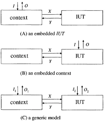
3 A test architecture of distributed systems [48] 9
4 Context-based testing: types of test architecture 10
5 FSM Mi of the connection establishment protocol for one participant . . . 17
6 Illustration of the weakness of the U-method 23
7 An illustration of the necessity of state identification 26
8 An illustration of the necessity of transition verification 27
9 Illustration of the construction of G'. The nodes in U' and V are on the
top and at the bottom respectively. The solid bold arrows and the dashed
arrows denote the edges in Eai U Ec and ET, respectively. 32
10 An illustration of the construction of G* = (V*,E*). Paths in A U B are
represented by bold solid arrows, and D-overlaps among paths in A U B are
represented by the dashed arrows 34
11 An example FSM M2 38
12 An illustration of test executability problem caused by improper order of
test sequence 40
13 An illustration of test executability problem caused by intrinsically
non-executable transitions 41
14 An example application of stateless embedded context 41
15 An illustration of solving executability problem for an IUT with stateless
embedded comtext 42
16 An example: online flight reservation system 46
17 An example with split states and weights 46
18 Specification FSM of the borrowing library 59
19 Specification extended FSM of the lending library 60
20 Promela model of the lending library 61
J INTRODUCTION 1
1 Introduction
Finite State Machines (FSMs) have been widely used to model the abstract behavior of
sequential circuits [32, 74], lexical analysis systems [51], and more recently, communications
protocols [1, 11, 63, 85]. Furthermore, some more expressive specification languages such as
Specification and Description Languages (SDLs) [50], Estelle [49], and Statecharts [69] are
based on extensions of FSMs. The demand of ensuring the correctness of computer systems
motivates the research on conformance testing in a setting where system specifications are
given in FSMs or FSM-based languages [1, 6, 11, 32, 38, 59, 63, 77, 80, 85].
Given an implementation under test (IUT) for which we can only observe its input/output
behavior, conformance testing can be conducted to improve our confidence that this
im-plementation conforms to its specification. Conformance testing is often carried out by i)
constructing from the specification of the system a test sequence, which is an input sequence
with an expected output sequence; ii) applying the input portion of this sequence to the
IUT, which is considered as a black box, according to the given test architecture; and iii)
determining whether the actual output sequence is produced as expected.
Given specification M describing the expected behavior of the IUT, we can imagine
that the IUT behaves according to a certain abstract machine N in the same format. In
this setting, conformance testing amounts to establishing the correspondence between M
and N. In doing so, it is essential to understand the fault models. In the following, for
convenience, we also use the IUT to represent the implementation FSM N.
A faulty IUT falls into one of the following categories.
• output faults: the IUT produces an incorrect output in response to an input in a
state.
• transfer faults: the IUT ends at an incorrect state after applying an input sequence.
• hybrid faults: the IUT has both output faults and transfer faults.
Based on these fault models, a series of fault coverage criteria and test generation methods
1 INTRODUCTION 2
Testing an IUT in isolation is not always feasible in the unit testing. There are situations
when we have to test the IUT together with some other components. As pointed out in
[73], this can be the case when the IUT is an embedded component of a complex system,
called a context of the IUT, only through which the IUT can be accessed. As another
example, suppose we want to test a web-based implementation WSi, which makes use
of web service WS^- Due to the difficulty in providing input and observing output all
encapsulated according to certain protocol such as SOAP [91], testing WS\ invokes the
necessity of activating WS2- Here, again, WS2 is considered as the context of WS\. In
general, the context can be the system components, the drivers, the stubs, the test beds,
and so on.
Obviously, it is worthful to study how to test an IUT within its context. Petrenko et
al. first presented a test generation framework for an embedded IUT whose communication
with the environment has to be carried out through its context [72, 73]. In particular,
the problems of test executability and fault propagation are addressed in the presence of
the context. The test executability problem describes the situation where a test sequence
generated from a given specification solely without taking into account the behavior of
the context may not be executable when testing in context, and the fault propagation
problem describes the situation where the faults of the IUT are masked by the context. In
[23, 24, 57, 70], different approaches are discussed for solving the problem of translating
internal tests derived for an embedded component into external observable tests of the
entire system.
Different from their application domain, our work is applicable to an IUT with an
embedded context, i.e. it does not communicate with any component other than X. In
our current work, we consider the problem of FSM-based deterministic testing on (2,XC)
which is an IUT implementation X together with a correct context implementation Xc.
The communication port between X and Xc is not controllable but observable. This means
that the tester can neither provide input to the IUT using this port nor stop an input
from the context to the IUT. It can, however, observe all the input from and all the
output to the context. The specification of I is given in terms of an FSM. Xc can be
1 INTRODUCTION 3
of a set of (request, response) pairs. When 2C is stateful, we assume that it is specified
by a specification language or a structural modelling language. In both cases, we present
methods to generate a minimal-length test sequence that can be used to test (2,2C) without
encountering test executability problem during testing.
When the context is stateful, the existing test generation techniques of testing in context
often suffer from the state explosion problem. This is caused by requiring the computation
of the product of several auxiliary components in addition to the model of the specification
of 2. The ultimate goal of our work is to avoid generating the operational model of the
given specification of 2C (if a higher level specification is provided) and constructing the
global model of 2 and 2C. In order to do so, we employ model checking tools to retrieve
necessary information from the context specification so that test sequences for (2",XC) can
be generated. The idea of using a model checking tools to generate tests is not new. In the
literature, various applications have presented. Ammann et al. combined model checking
with mutation analysis to generate test cases [2]: after a specification model is mutated by
applying mutation operators, a model checker generates counter-examples to distinguish
the mutant models from the original specification model, and thus test cases are derived.
Gargantini and Heitmeyer presented a technique to construct test sequences upon a special
class of so-called Software Cost Reduction requirements, by using a model checker [26]. In
order to save memory from a huge predefined test suite, Tretmans and de Vries [17] used
model checker SPIN to generate tests during testing for non-deterministic stateful systems.
How to generate test cases according to some data flow test selection criteria is discussed
in [45]. In [75], Goltz et al. used a model checker to generate a shortest distinguishing
sequence of an EFSM.
Note that it is straightforward to extend our work to a more general case where the
embedded context consists of a set of components, each having its own port to communicate
with I . In terms of applying model checking tools for test generation, we have added one
more example along this line of research, particularly for testing in context.
We consider conformance testing of deterministic systems in this dissertation. The
readers who are interested in conformance testing of non- deterministic systems should refer
2 FINITE STATE MACHINES AND RELATED FAULT MODELS 4
The rest of the dissertation is organized as follows. In Chapter 2, we give a brief
in-troduction to FSMs and the related notations and terminologies that will be used later on,
followed by a discussion of the fault models of FSMs. The main issues of testing in context
are addressed in Chapter 3. Among those issues, four widely used fault coverage criteria
together with some existing test generation and optimization techniques are discussed in
Chapter 4. In Chapter 5, test executability problem is explained. Test generation
tech-niques for an IUT with stateless and stateful embedded context are presented in Chapter
6 and 7, respectively. In the end, we conclude our work with some final remarks.
2 Finite state machines and related fault models
There are various formalisms to describe the expected behavior of a stateful system.
Suit-able for different levels of abstractions, they range from formal specification languages such
as process algebras, to structural/operational modelling languages such as (input/output)
labelled transition systems (LTSs) and Finite State Machines (FSMs). Here, we use FSMs
to show the main issues related to testing in context.
2.1 F i n i t e s t a t e m a c h i n e s
There are two types of FSMs: Mealy machines [61] and Moore machines [66]. The difference
between them lies in how an output is determined: For the former, an output is determined
by the current state and an input; while for the latter, an output is determined by the
current state alone (not directly by an input). Usually, the number of states in a Moore
machine is greater than or equal to that in an equivalent Mealy machine. We adopt Mealy
machines since they are more natural to model software systems. As mentioned in the
Introduction, we consider deterministic FSMs. In order to explicitly associate each input
and output with a port (an interface to communicate with a certain component), we use
n-port FSM to describe the abstract behavior of the systems with n ports.
Definition 1 (Finite state machines) A deterministic n-port Finite State Machine (also
called finite state machine for short) is defined by a tuple (S,I,0,S,X,SQ).
2 FINITE STATE MACHINES AND RELATED FAULT MODELS 5
• I = \Ji=i U, where Ii is the input alphabet of port i (i = 1 , . . . , n).
Being abstract, these input symbols encapsulate the information of the communication
channels. Thus, without loss of generality, we can assume that the input symbols at
different ports are distinct, i.e. Ii nlj = 0 for i ^ j .
• O = II"= 10j where 0{ is the output alphabet of port i (i = 1 , . . . , n).
Each o £ O is a vector of outputs denoted by o = (o\,... ,on) where Oi € Oi for
i = 1 , . . . , n. We do not consider the order in which we observe output Oi and Oj at
different ports. When there is no output at a port i, we use a distinct symbol — to
denote it.
• S is the transition function that maps S x I to S, and
A is the output function that maps S x I to O.
A "slow environment" assumption is usually used in the literature. That is, whenever
an input reaches the system, the system will always prompt the output for it before the
second input can reach the system.
The inputs and the outputs are abstract symbols. The discussions on data types and
complicate data structures in the inputs and outputs are beyond the scope of this
disser-tation.
Note that functions A and S can be partial, i.e., it is possible that there exists i 6 / for
some s E S such that A(s, i) = null and 5(s, i) = null. We will use 5(s, x) = null to denote
that there is no image of 6 for the given state s of S and the given input x of I. In this case,
we also have A(s, x) = null. Furthermore, we extend the input of A and 8 from an input
alphabet to a sequence of input alphabets with their meanings obtained straightforwardly
from the original ones.
For simplicity, we assume the number of states of M is n and the states of M are
enumerated, giving S — {so,..., s„_i}.
A transition t is defined by a tuple (si, S2, x/y) in which si is the starting state, x is the
input, «2 = <Hsi>x) is the ending state, and y = X(si,x) is the output. The input/output
2 FINITE STATE MACHINES AND RELATED FAULT MODELS 6
one output for each transition of an FSM, we use a single output alphabet instead of an
output vector to denote the output for simplicity.
Let U be a transition for 1 < i < k. A path p = t\ t<i . . . £& is a finite sequence of
transitions such that for k > 2, the ending state of U is the starting state of U+\ for all
1 < i < k — 1. A tour is a path whose starting state and ending state are the same. For
convenience, we use start(p), end(p), label(p), and in{p) to denote the starting state, the
ending state, the label, and the input portion of the label of p, respectively.
Let pi and p2 be two paths of M. When end{p\) and start{p2) are the same, we use
pip2 to denote the concatenation of p\ and pi- For clarity, sometimes we also use p\ o p2
for pip2. For pi = (si, sh, Ti) and p2 = (sh, sr,T2), we have p = pi o p2 = (sx, sr, 7\ o T2).
A state s £ S is reachable if there exists a path starting from so and ending at s. We
consider FSMs where all states are reachable.
An FSM is completely specified if functions A and 5 are total; otherwise, it is partially
specified. When an FSM M is not completely specified, it is possible to make M completely
specified. Two typical ways of doing so are named after [16].
• angelic completion: for any (s,x) £ domain(5), add transition (s,s,x/null).
• demonic completion: i) add an erroneous state serr; ii) for any (s, x) ^ domain(8), add
transition (s,serr,x/nult); and hi) for any x £ I, add transition (serr,serr,x/null).
The completion, however, slightly changes the meaning of the FSM and is not always
acceptable.
Two states Si and Sj are equivalent if, for every input sequence a, A(sj,cr) = X(sj,a). If
A(SJ, a) ^ X(SJ, a) then a distinguishes between Sj and Sj. An FSM M is minimal if every
state can be reached from the initial state of M and no two states of M are equivalent.
Since only deterministic FSMs are considered, we can easily obtain a minimal FSM from
any given FSM [27, 46]. In the following, we assume that all given FSMs are minimal.
When the specification of an IUT is given in the form of an FSM, we would like to
automatically generate an efficient and effective test sequence from it. Here, a test sequence
refers to an input sequence, which is typically obtained from a path of the given specification
2 FINITE STATE MACHINES AND RELATED FAULT MODELS 7
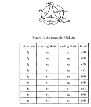
Figure 1: An example FSM M0
transition
ta
t\
ti hn
h h h h starting state so so so s\ s\ s i S2 S2 S2 ending state s i S2 S2 S2 S2 so S i so S2 label a/0 6/0 c/0a / 1
6/0
c/0
a / 1
6/0
c/0
Table 1: Transitions in MQ
the input portion of this path is the desired test sequence and the output portion of this
path is the expected output sequence.
Example 1 An example 1-port FSM MQ is given in Figure 1. Here, S = {so,si,S2J,
/ = {a, b, c}, and O = {0,1}. Transitions in Mo are listed in Table 1. <>
2.2 Fault m o d e l s
Fault models can serve as a guide to test generation and fault coverage analysis, as claimed
in [89]. When, a specification M and its IUT have the same input alphabet and output
2 FINITE STATE MACHINES AND RELATED FAULT MODELS
(A) Specification M0
a/0>
(£
c/0, ^ a/1 a/0 -WO.kbAV ,b/(V
>oL
C/0iJc/0
(B) An [UT with an output fault
a/i(
~Z&--~.
* ° / W \b/o\b/o)c/0
^^l/^aii^V I J
a/o(
^ @ T - \
M
/cJ V n
T
/0
_ ! / a/1 XAJ
fir :©""")
(C) An 1UT with a transfer fault (D) An IUT with a hybrid fault
Figure 2: Faulty IUTs of example FSM M0
• An IUT has only output faults if M can be obtained from the IUT by changing the
outputs of one or more transitions in the IUT.
• An IUT has only transfer faults if M can be obtained from the IUT by changing the
ending states of one or more transitions in the IUT.
• An IUT has hybrid faults if M can be obtained from the IUT by changing the outputs
and/or the ending states of one or more transitions in the IUT.
Here, we do not consider the fault type of extra states, i.e., the number of states of
the implementation FSM will not exceed that of the specification FSM. We argue that
this assumption is reasonable. As we know, the purpose of the conformance testing is to
ensure that the behavior of the implementation conforms to the behavior specified by the
specification. The existence of the extra states means the existence of the extra behavior
which is not specified by the specification, and thus will not be tested.
E x a m p l e 2 Figure 2 shows three faulty IUTs of Mo- The shaded area surrounding an IUT
represents the black box where only inputs and outputs can be observed. When transition
3 MAIN ISSUES IN TESTING IN CONTEXT
Test System
Lower Tester
i L
X- ASPs
Test Coordination Procedure
P, to Pn
PDUs
SUT Upper Tester i
Y-T ASI
1UT
Ds
X-Service Provider
(N) - ASP: abstract N-service primitive, an implementation-independent description of an interaction between a user and a service-provider at an (N)-service boundary.
PDU: protocol data unit.
Figure 3: A test architecture of distributed systems [48]
fault, a transfer fault, and a hybrid fault, respectively.
•
Based on the above fault models, we want to automatically generate an effective and
efficient test sequence from a given specification, i.e., it is desirable to generate a test
sequence as short as possible while detecting as many faults as possible. This is known as
the fault coverage problem and the test optimization problem. We will discuss the existing
solutions to these two problems in Chapter 4.
3 Main issues in testing in context
Ideally, an IUT can be tested in isolation, i.e., a tester can apply a desired input directly to
the IUT and observe the actual output produced by the IUT directly. In practice, however,
it is not always feasible: the IUT is often tested through its environment, called context.
For example, in the distributed test architecture shown in Figure 3, the underlying network
is the context of the IUT since it has to be used when the lower tester interacts with the
IUT.
According to the ways of the interactions among the tester, the IUT, and the context,
Fig-3 MAIN ISSUES IN TESTING IN CONTEXT 10
context
X ' Y
IUT
(A) an embedded IUT
>\\°
context
X *Y
IUT
(B) an embedded context
1 '
A
contc
Y*
X * Y
M h
IUT
(C) a generic model
Figure 4: Context-based testing: types of test architecture
ure 4. Here, for simplicity, we demonstrate these architectures by treating the context as
one component even though it may include multiple components instead. Petrenko et al.
considered the situation where the IUT is an embedded component whose communication
with the environment has to be carried out through its context, as shown in Figure 4(A).
In [72, 73], they presented a framework of testing an embedded component in context.
Along this direction, different approaches [23, 57, 70] are discussed for solving the problem
of translating internal tests derived for an embedded component into external observable
tests of the entire system. Different from their test architecture, we consider how to test
an IUT that is associated with an embedded context as shown in Figure 4(B) [21].
The existence of the context may introduce additional problems for testing. In the
previous example, when the underlying network is not transparent, in the sense that it has
its own behavior, it is possible that both the inputs applied from the lower tester and the
outputs produced by the IUT are modified by the underlying network. Consequently, the
3 MAIN ISSUES IN TESTING IN CONTEXT 11
to be considered for the test generation. In the following, we first introduce the external
equivalence for context-based systems and then discuss the main issues in this setting.
3.1 E x t e r n a l equivalence
Let K. be a system consisting of a finite set of FSMs Mi = (Si, Sifi, Xi,Yi,6i, \i), where
i = 1 , . . . , k. Here, we assume all the actions in Xi, Yi are distinct. Suppose I C\JiXi and
O C Uj Yi are the sets of the external inputs and the external outputs regarding the entire
system, respectively. For K, to be a meaningful system, we have the following assumptions.
• 7 D (ij^ Yi) = 0, i.e., an external input cannot be produced by any component FSM.
• O n (U^ Xi) — 0, i.e., an external output cannot be accepted by any component FSM.
• (Ui Yi) \ O C (\}i Xi) \ I, i.e., any internal output should be accepted by some
com-ponent FSM.
We say FSM Mi communicates with FSM Mj if there exists an internal action in set
Yi D Xj. The communication among component FSMs can be either synchronous or
asyn-chronous. We assume that the communication channels are reliable. A global FSM of
a asynchronous/synchronous communication can be composed by performing reachability
analysis [7, 62, 90, 93, 97]. In black-box testing, we are particularly interested in
syn-chronous composition, where all the internal actions are hidden and only external inputs
and outputs are indicated. In the following, we use operator x to denote the synchronous
product of component FSMs.
In the realm of deterministic FSMs, two FSMs are trace equivalent if for any input
sequence, they produce the same output sequence in response. For testing in context,
external equivalence is defined by taking into account the behavior of the context. Note
that the following definition is adopted from [73] with slight modification.
Definition 2 (External equivalence) Let Si and S2 be two FSMs, and C their context
FSM. «Si is externally equivalent to S2 w.r.t. C, denoted by Si =c S2, if Si x C is trace
3 MAIN ISSUES IN TESTING IN CONTEXT 12
The goal of testing in context is to ensure that the IUT is externally equivalent to its
specification in a given context. Test generation aiming at ensuring external equivalence
needs to take into account the behavior of the context.
3.2 M a i n i s s u e s
Many issues arise for testing in context.
• stateless v.s. stateful. When the IUT and its context are stateful, test generation
may suffer from the state explosion problem. Specification languages such as FSMs,
Extended FSMs, and Labeled Transition Systems are often used to specify stateful
systems. In this work, we consider the situation where the stateful IUT is specified by
an FSM while its embedded context is either stateless or stateful. In the latter case,
we require that the context be specified by a specification language that can be
trans-lated to Extended Finite State Machines (EFSMs), which is a concise specification
formalism that allows the use of variables.
• deterministic v.s. deterministic. Studies on both deterministic testing and
non-deterministic testing have practical significance and confront different challenges. We
are particularly interested in test generation techniques of deterministic systems
be-cause two benefits can be provided.
- A high level confidence on the correctness of the IUT can be ensured by applying
a test sequence whose length is polynomial to the size of the IUT. For example,
trace equivalence can be guaranteed with a checking sequence whose length is
polynomial to the number of transitions under certain conditions. The detailed
discussion on this regard is in Chapter 4. On the other hand, test sequences of
non-deterministic systems are often of infinite length [82] or much more costly
by requiring to repeat the testing for many times with the fairness hypothesis
that all the possible paths with non-deterministic choices are tested, which it
actually can not be always guaranteed.
- If we can derive from deterministic testing that components I\ and Ii are trace
circum-3 MAIN ISSUES IN TESTING IN CONTEXT 13
stances we know hWh is a correct implementation of P1IIP2 without performing
further integration testing or system testing which involves nondeterministic
sys-tem specifications.
In this work, we consider the case when both the IUT and its context are deterministic.
• test criteria. Many fault coverage criteria have been proposed in the literature. In
Chapter 4, four widely used criteria for FSM-based test sequence generation are
ex-plained, namely, the T-method, the U-method, the D-method, and the W-method.
In this work, we choose the T-method in Chapter 6 and the W-method in Chapter 7
to demonstrate our proposed methods. Other criteria are applicable with proper
adaptation.
• optimization on the efficiency. It is always desirable to reduce the time complexity to
generate tests and to reduce the time to carry out the testing while a certain desired
fault coverage is satisfied. The existing optimization techniques for different fault
coverage criteria are discussed in Chapter 4.
• internal observer v.s. external observer only. An internal observer is an observer who
can passively observe the interactions between IUT and its context although it has
no control on them. An external observer is actually a tester who has the control
to give the inputs and observe the outputs. When an internal observer is available,
better testing results can be achieved by making use of the knowledge obtained by
observing the internal interactions. We assume the internal observer is available.
• fault propagation. The problem of fault propagation describes the fact that some
faults of the IUT can be tolerated by the context. There are two types of reasons
resulting in the tolerance: i) the selected test sequence is incomplete in the sense
that it can not distinguish all the faulty implementation; and ii) some faults are
intrinsically tolerated by the context such that no tester can detect them. Note that
the fault propagation problem does not exist when an internal observer is available.
4 FAULT COVERAGE AND TEST OPTIMIZATION 14
• test executability. Test executabitity problem describes the situation where a test
sequence generated solely from a given specification without taking into account the
behavior of the context may not be executable when we carry out testing in context.
This problem is caused by the uncontrollable interaction between IUT and its context
during testing. This problem is crucial in testing in context, and we have a detailed
discussion in Chapter 5.
4 Fault coverage and test optimization
It is well known that the exhaustive testing is impossible in practice, and a tester has to make
a tradeoff between the fault coverage and the cost. When the IUT has certain properties,
it is possible to utilize these properties to maximize the fault coverage. These desirable
properties include the reliable reset, the existence of some special input sequences which
can be used to identify the states in the IUT, etc. In this chapter, we introduce four typical
test generation methods along with the corresponding optimization techniques. Namely,
these methods are the T-method [68], the U-method [1, 63, 76], the D-method [29, 32, 85],
and the W-method [11]. Actually, these methods can also serve as fault coverage criteria.
4.1 G r a p h representations of F S M s
Since most of the algorithms for test sequence generation are based on some well-known
algorithms in graph theory, in the following, we introduce the graph representation of an
FSM and several typical problems in graph theory.
Each FSM M has a graph representation G = (V,E,L), in which a state of M is
represented by a vertex from V and a transition of M is represented by an edge from E.
We use GM to denote the graph representation of FSM M, where state Si is represented by
vertex V{, and transition from S{ to Sj with label x/y is represented by edge (vi,Vj,x/y).
Terminologies and notations defined for FSMs are naturally extended to their graph
representations.
A digraph is strongly connected if for any ordered pair of vertices (vi, Vj) there is a
4 FAULT COVERAGE AND TEST OPTIMIZATION 15
contains every edge of E at least once. Given digraph G = (V, E, cost), where cost is a cost
function that associates each edge in E with a cost, we say G is a weighted digraph. The
Chinese Postman Problem (CPP) is to find the minimum-cost Postman Tour in a strongly
connected (weighted) digraph. Given a strongly connected G = (V, E) and E\ C E, a Rural
Postman Tour is a tour which contains each edge in E\ at least once. The Rural Chinese
Postman Problem (RPP) is to find a Rural Postman Tour with minimum cost. CPP has a
polynomial time solution while RPP is in general NP-hard. Various sophisticated heuristics
have been proposed in the literature for RPP (see e.g. [22]).
4.2 T - m e t h o d
The fault coverage criterion specified by the T-method [68] is as follows.
• T-method: The corresponding path of the generated test sequence in the specification
FSM M should contain each transition in M at least once.
According to the T-method, a transition is tested to be correct when its output is
correct in response to the corresponding input. If a faulty IUT has only output faults, test
sequences generated with the T-method are capable of detecting any faults; otherwise, a
faulty IUT may not be distinguished. The advantage of the T-method is that shorter test sequences are generated.
Clearly, the optimization problem of generating a minimal-length test sequence can be
reduced to Chinese Postman Problem (CPP).
E x a m p l e 3 Given specification Mo in Figure 1, a tour g is found:
Q = tohtetstitgtetiit^h
Then a test sequence of length 11 can be derived by concatenating the inputs of g:
X = in(g) = aaacbcabbcb, whose expected output sequence is 01100010000.
The faulty IUTs in Figure 2(B) and (D) can be distinguished by x since the actual
output sequences are 00100010000 and 00000010000, respectively. However, the faulty IUT
4 FAULT COVERAGE AND TEST OPTIMIZATION 16
states
so
Sl
S2
S3
54
UIO sequence
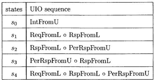
IntPromU
ReqFromL 0 RspFromL
RspFromL 0 PerRspFromU
PerRspFromU 0 RspFromL
ReqFromL 0 RspFromL 0 PerRspFromU
Table 2: UIO sequences for each states in Mi
4.3 U - m e t h o d
The U-method can be applied to a special class of FSMs that have a Unique Input/Output
sequence (UIO sequence) for each of their states. Given an FSM M, a UIO sequence of
a state s is an input sequence such that the corresponding output sequence obtained by
applying this input sequence at s in M is unique from those obtained by applying this input sequence at any other state. We use UIOi to denote the UIO sequence for state s*.
Formally,
Definition 3 (UIO sequences) Given an FSM M = (S, I, O, 5, A, SQ), an input
se-quence UIOi is a UIO sese-quence of state si if for any Sj € S, Sj ^ Sj implies A(SJ, UIOi) 7^
A(Sl,UIOi).
Example 4 We present here a protocol for establishing service connection, which is
com-monly used in peer-to-peer systems. In this protocol, any participant, upon receiving a
request from its user, can initiate a connection with any other peer participant by issuing a
connection request. The connection will not be established until the confirmations from all
peer participants are received. Each confirmation represents the permission from another
participant. For simplicity, we consider such a protocol with two participants.
Note that the connection requests can be issued concurrently by both participants. That
is, the two participants may issue the requests at about the same time. Consequently, it is
possible that each participant receives a connection request from the other participant right
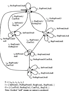
4 FAULT COVERAGE AND TEST OPTIMIZATION
t,: PerRspFromU/nullI
tl2: RspFromL/, ConfToU
it4: RspFromL/null
t|4: PerRspFromU/
t,: ReqFromL/ \ConfToL
erReqToU
. t„: InlFromU/null
) t]5: ReqFromL/null
t16: RspFromL/null
tn: ReqFromL/null
tl0: PerRspFromU/ConfToL
tl7: IntFromU/null t.„: ReqFromL/null
tl8: PerRspFromU/null
^ — I s0, st, s2, s,, s4 }
I = { IntPromU, PerRspFromU, ReqFromL; RspFromL O = ( ConfToU, PerReqToU, ConfToL, ReqToL ) Note: Symbol "null" means no output is produced.
4 FAULT COVERAGE AND TEST OPTIMIZATION 18
partner. In this case, in order to establish a connection, each participant should respond
to the request from its partner as well as receive the confirmation from its partner for its
own request.
The specification FSM M\ = (S, 1,O,5, A, so) of a participant in this protocol is shown
in Figure 5. The service primitives and their symbolic representations for each participant
in this protocol are listed below.
• IntFromU: user's intention for establishing a service connection;
• ReqToL: message to request the partner to establish connection;
• RspFromL: response from the partner for service connection;
• ConfTo U: confirmation of the service connection to the user;
• ReqFromL: request from the partner for service connection;
• PerReqToU: request for the user's permission for service connection;
• PerRspFrom U: user's permission for a service connection;
• ConfToL: confirmation of the service connection to the partner.
Suppose process A is a participant of this connection establishment protocol modeled by
Mo- I/O pair IntFromU'/ReqToL means that upon receipt of message IntFromU, A will send
a request to its partner for the connection establishment. I/O pair ReqFromL/PerReqToU
represents that when A receives message ReqFromL, it will send a request to its user asking
for permission.
Table 2 shows the shortest UIO sequences for each state.
0
Not every FSM has a UIO sequence for each of its states, and the problem of finding
UIO sequences for an FSM is very hard [55]. For a given specification M, the following
decision problems are proven to be PSPACE-complete: i) whether a specific state s of M
have a UIO sequence; ii) whether all states of M have UIO sequences; iii) whether some
4 FAULT COVERAGE AND TEST OPTIMIZATION 19
sequence, it is possible that this UIO sequence is of exponential length. In this case, there
is no value for testing purpose. Note that these are the worst case result. In practice
(e.g. communication protocols), short UIO sequences exist for most cases and can be found
quickly [56]. Discussions on finding the UIO sequences from a given FSM can be found in
[12, 28, 18, 47, 56, 76].
For conformance testing, UlOi can be used to verify whether an IUT is in a state
corresponding to state S{ since the desired output sequence is supposed to be produced
when applying UlOi in Sj. This property can be used to tackle the transfer faults in IUTs
in the sense that the ending states of transitions can be verified with UIO sequences. Thus,
the U-method is inspired.
The fault coverage criterion specified by the U-method [1, 63, 76] is as follows.
• U-method: The corresponding path of the generated test sequence in the specification
FSM M should contain each transition in M with its ending state in the
implemen-tation FSM verified.
E x a m p l e 5 Suppose we want to generate a test sequence from specification Mi in Figure 5
with the U-method. For simplicity, we only consider two transitions, namely, £9 and £20! as
examples.
Let p9 = £g£i2ii4 and P20 = ^20^1 be two paths in Mi. Since the input portion of
label(ti2tu) is a UIO sequence for the ending state of transition £9, the ending state of £9 is
verified by applying the input portion of pg. That is, pg can be used to test the correctness
of £9. We call such a path a test segment of £9. Similarly, P20 is a test segment of £20- Using
transfer sequence £i£7£io to connect these two test segments, we get
p = £9*12*14*1*7*10*20*1
which is a path containing both test segments.
Analogously, a path g in M can be found containing the test segments of all the
tran-sitions in Mi. Then the input sequence in(g) is a desired test sequence satisfying the
4 FAULT COVERAGE AND TEST OPTIMIZATION 20
4.3.1 Test o p t i m i z a t i o n
As the U-method is effective to detect the transfer faults in the IUTs, it is appealing to
study on how to minimize the lengths of the generated test sequences. In the literature, a
lot of contribution has been made in this regard [1, 9, 10, 20, 33, 34, 63, 76, 78, 95], and
the main ideas of these work are to maximize the overlaps among the test segments and
to reduce the use of the transfer sequences connecting test segments. In the following, we
explain some latest results along this approach.
In [33], Hierons proposed the notion of the invertible transitions1. A transition (SJ, Sj,x/y)
is invertible if it is the only transition entering state Sj with input x and output y. In the
example FSM M\, £i, £2, £3 are invertible transitions while £s and £20 are not because both
£g and £20 end at so with the same label RspFromL/ConfToU.
The existence of invertible transitions in existing protocol descriptions has been the
major source of the recent success in reducing the lengths of the generated U-sequences.
This is based on the following observation ([63, 33]):
O) If £ is an invertible transition and UlOi is a UIO sequence of end(t), then the input
sequence in(t) o UlOi is a UIO sequence for start(t).
Suppose that £ is an invertible transition, and to is a test segment for £ in the sense
that a is a path induced by applying the UIO sequence of state end(t) at end(t). Now if
t' is a transition adjacent to £ in the sense that end(t') = start(t), then path £'£cr is a test
segment for £'. As £'£cr contains test segments for both £' and £, we say there is an overlap
between test segment £'£cr and test segment to. By using invertible transitions, the overlap
between test segments is increased. It follows that the length of the generated U-sequence
can be reduced.
Some heuristic algorithms have been proposed in [63, 33] to maximize the use of
in-vertible transitions to reduce the lengths of the U-sequences. In doing so, the notion of
invertible transition is extended to that of invertible sequence [34]. A path p is an invertible
sequence if it is the only path with label label(p) that ends at end(p). That is, for any path
4 FAULT COVERAGE AND TEST OPTIMIZATION 21
p', start(p) •£ start(p') implies end(p) ^ end(p') or label(p) ^ label(p'). Clearly, when the
length of an invertible sequence is 1, it is actually an invertible transition.
Similar to O), we have the following result [34]:
O') If p is an invertible sequence and UlOi is a UIO sequence of end(p), then the input
sequence in(p) o UlOi is a UIO sequence of start(p).
Note that the additional UIO for start(p) obtained from O') may be longer than the
given UIO sequence for start(p). For the example in Figure 5, £10*20 is an invertible sequence
ending at SQ. We know that UIOQ =• IntFromU and UIO2 = RspFromLoPerRspFromU.
By using invertible sequence £10*20, we have another UIO sequence for
S2-UIO'z = PerRspFromU o RspFromL o IntFromU.
Although this newly found UIO sequence is longer than the given one, it may help to reduce
the total length of a U-sequence since the test segment it produced has an overlap with
other test segment(s). Let us use pi to denote the test segment formed by concatenating U
and the path induced by applying the originally given UIO sequence of end(U) at end(ti).
Consider the two test segments for transitions £9 and £20 in MD- We have p$ = tgtutu and
P20 = £20*1- Using transfer sequence t^tio to connect these two test segments, we get
P = t9ti2tutit7tiot2oti
which is a path containing both test segments. The length of p is 8. If we use the UIO
sequence derived according to O'), one of the test segments for £9 is p9 = tgtio^o^i which
contains p2o- In this case, p9 can be used to verify both £20 and £9 and its length is only 4.
With this observation, a heuristic algorithm was given in [34] to use the invertible sequences
to reduce the length of U-sequences.
As from O) an optimal solution was derived for finding a minimal-length U-sequence in
the special case when all transitions in M are invertible, now for general FSMs which may
contain both invertible transitions and non-invertible ones, O') leads to the following idea:
a') Determine a minimal-length path g — tv>o\t\c<it2 • • •0'fc£fc0'o> where for 0 < % < k, a{ti
4 FAULT COVERAGE AND TEST OPTIMIZATION 22
U = t. Without loss of generality, we assume to is a transition starting from the initial
state
so-b') Obtain p by removing GQ from g and appending path p' induced by applying the UIO
sequence of end(tk) at state end(tk).
Then, in(p) can be used as the desired test sequence. This is formally introduced below.
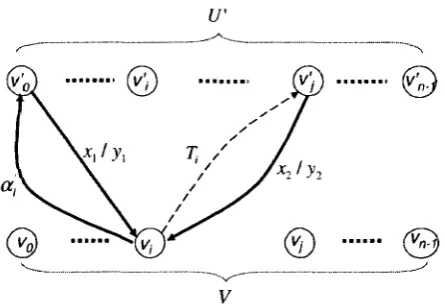
Definition 4 (proximate test path) Let M be a given FSM. Suppose i, is a transition in
M and cr, is a path in M (0 < i < k). A proximate test path of M is g = i o o i ^ i0^ • • • Cktk&o
such that:
• to is a transition starting from the initial state SQ;
• Vi € { 0 , . . . , k}. 0{ti is an invertible sequence;
• Vt G M, 3i (0 <i<k) such that t = U.
Let g = too--[t\(j2t2 • • • °~ktkO~o be a proximate test path of a given specification M , where
ti is a transition and 0{ is a path in M such that Uiti is an invertible sequence for 1 < i < k.
If end(tk) = sm, then in(tocriti<T2*2 • • • o"fc^fc) ° UIOm is a test sequence satisfying the
U-method.
The algorithms on how to find a minimal-length proximate test path of M is explained
in details in [20]. Given specification M\ in Figure 5, a test sequence of length 26 can be
generated by the approach in [20] compared with that of length 72 by the approach in [1]
and that of length 31 by the approaches in [63, 33].
4.3.2 Weakness and strength of the U-method
The U-method does not support the full fault coverage due to the following two main
reasons.
i) It does not check whether the starting states of transitions are correct. That is, when
a transition starts from a wrong state in the IUT, no mechanism from the U-method
4 FAULT COVERAGE AND TEST OPTIMIZATION 23
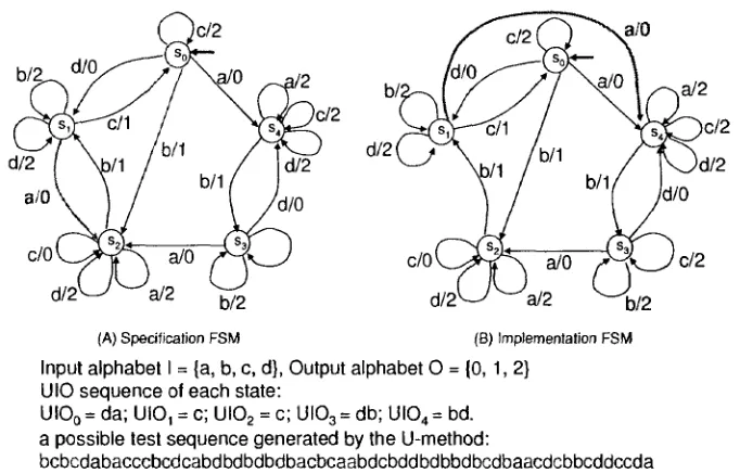
(A) Specification FSM (B) Implementation FSM
Input alphabet I = {a, b, c, d}, Output alphabet 0 = (0,1, 2} UIO sequence of each state:
UIO0 = da; UIO, = c; UI02 = c; UI03 = db; UI04 = bd.
a possible test sequence generated by the U-method:
bcbcdabacccbcdcabdbdbdbdbacbcaabdcbddbdbbdbcdbaacdcbbcddccda the corresponding expected output sequence:
101100100001101010101010100110210210210120120102020121021200
Figure 6: Illustration of the weakness of the U-method
ii) The uniqueness of the output sequence in response to a UIO sequence in the
speci-fication does not guarantee the uniqueness of that in the IUT. In a faulty IUT, it is
possible that there are other states such that the same output sequence is produced
by applying the UIO sequence in those states. Consequently, the state verification
fails.
E x a m p l e 6 A faulty IUT (Figure 6(B)) of the specification shown in Figure 6(A) has a
transfer fault for transition (si,S2,a/0): instead of ending at state 52, it ends at state S4
in the IUT. The IUT passes the testing with a test sequence generated by the U-method
since the actual output sequence produced by the faulty IUT is the same as the expected
one with this test sequence. In this case, the testing fails to detect the above transfer fault.
The strength of the U-method is that it can achieve a satisfactory fault coverage with
4 FAULT COVERAGE AND TEST OPTIMIZATION 24
much more effective in detecting faults; On the other hand, the U-method generates much
shorter test sequences and are less restrictive than those methods (e.g. the D-method and
the W-method) supporting the full fault coverage. For example, the U-method does not
require a completely specified specification, reliable reset, a distinguishing sequence, etc.
Due to the benefits the U-method provides, it is desirable to incorporate the U-method
with the characterization sets (see Chapter 4.5 for the definition), which exist for all the
minimal FSMs, such that the U-method is applicable to all the FSMs. For example, in
[37], Hierons proposed a technique to generate a minimal-length test sequence satisfying
the U-method with a characterization set.
4.4 D - m e t h o d
The D-method is applicable to a special class of FSMs that have a distinguishing sequence
(DS) [27, 52]. Given an FSM At, a distinguishing sequence is an input sequence D with the
following characteristics: the output sequences produced by M in response to D in different
states of M are all different. Formally,
Definition 5 (distinguishing sequences) Given an FSM M = (S, I, O, 5, X, so), an
input sequence D is a distinguishing sequence of M if for all Si,Sj € S, Si ^ Sj implies
\(Si,D)^\(Sj)D).
Not every FSM has a DS. It is a PSPACE-complete problem to determine whether a
given FSM has a DS [55]. The classical algorithms of finding a DS are of exponential time
as discussed in [27, 52].
Clearly, a DS is a UIO sequence applicable to all the states. The existence of a DS of
an FSM implies the existence of a UIO sequence for each state of the FSM; but the reverse
is not true.
Example 7 In Figure 1, a distinguishing sequence for Mo is D = aba: when we apply
this input sequence to states SQ, SI and S2, the output sequences are 001, 100, and 101,
respectively. They are all different. <£>
Two FSMs Mi and Mi are equivalent if and only if for every state of'Mi there is an
4 FAULT COVERAGE AND TEST OPTIMIZATION 25
and only if it distinguishes between M and any FSM that has the same sets of input and
output alphabets as M but is not equivalent to M. Clearly, a checking sequence is a special
test sequence that guarantees the full fault coverage.
Assume that the IUT behaves like some (unknown) FSM N with the number of states
no greater than that of the specification M. Since M and N are deterministic and minimal,
determining whether N is equivalent to M can be achieved by establishing isomorphism
between M and N. More precisely,
• for each state s in M, we identify a state r in N that corresponds to s.
• for each transition t = (si,S2,x/y) in M, we verify that there exists a transition
t' = (ri,r2,x/y) in N which starts from a state corresponding to si, ends at a state
corresponding to S2, and gives the same output y upon the same input x.
A checking sequence is designed to help us to achieve the above two goals. With respect
to these goals, the construction of a checking sequence usually involves two steps: one for
state identification and one for transition verification [56].
The purpose of state identification is to build a one-to-one correspondence between the
states in M and those in N. State identification using UIOs is possible but it turns out to
be hard and less practical [40]. A characterization set (which is discussed in Chapter 4.5) is
easier to find than a distinguishing sequence, yet a test suite generated using a
characteri-zation set [11] is usually much longer than that generated using a distinguishing sequence
in terms of total length of the test sequences [8, 29, 32, 85]. Of course, DS can also be used
for state verification in the sense of verifying the ending states of transitions.
Recall that D = aba is a distinguishing sequence of Mo in Figure 1. If we apply D
to the IUT of MQ and observe 001, then we know that the state of N before we apply D
corresponds to so, which is the only state in Mo that gives output sequence 001 in response
to input sequence aba. Similarly, if we apply D to the IUT several times (at different states
of N) and observe 001, 100, and 101, then we know that N has (at least) three states and
the states of N before we apply each D correspond to so, «i and S2 respectively.
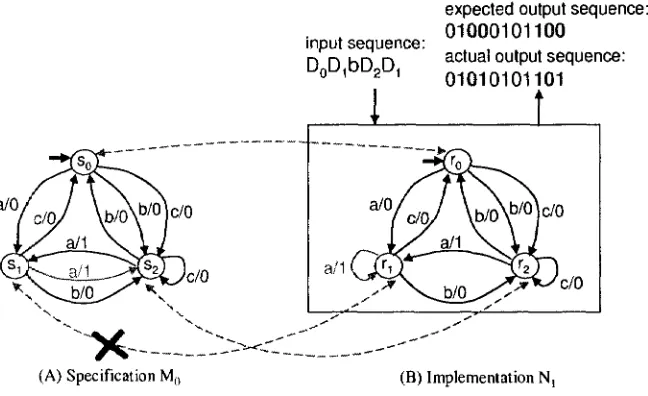
E x a m p l e 8 Suppose N\ shown in Figure 7(B) is an FSM describing the behavior of a
4 FAULT COVERAGE AND TEST OPTIMIZATION 26
expected output sequence:
(A) Specification M() (B) Implementation N,
Figure 7: An illustration of the necessity of state identification
Recall that for Mo in Figure 1, we have distinguishing sequence D = aba. As the
dashed arrows in Figure 7 show, we have ro corresponds to SQ and r<i corresponds to s<i
in the sense that X(SQ,D) = X(TQ,D) = 001 and X(s2,D) = X(r2,D) = 101. However,
X(s\,D) ^ X(ri,D): MO (at s\) and N\ (at n ) give different output sequences 100 and 101
respectively in response to input sequence D. In other words, at r\, the implementation
FSM iVi does not behave like M0.
We can detect that Ni is a faulty implementation of Mo on the stage of state
identi-fication: by applying D to the IUT, we fail to find a state in N\ which produces output
sequence 100 in response to D, as s\ does.
0
When a distinguishing sequence D of M is given, sometimes a prefix of D is sufficient
in helping us identify a state in N with a state in M. For example, in Figure 1, state so is
the only one that gives output 0 in response to input a. Thus, we can simply use a (which
is a prefix of D) as input to the IUT to identify a state in N that corresponds to so- We
will use Di to denote the prefix distinguishing sequence for Sj. It is the shortest prefix of
D that is sufficient to distinguish state Sj from others, i.e., for any state Sj where Sj ^ Sj,
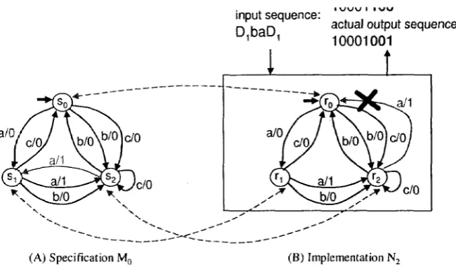
4 FAULT COVERAGE AND TEST OPTIMIZATION 27
input sequence: D,baD,
i \j\jyj i i v w
actual output sequence: 10001001
•^^c
/0
/c/o/ \b/0\
b/0]c/0
1 /
a/1 \ V i
1 t
/ ^ ? N ^ ^ N
M
fciJ U ^ j
1 / \ \ / - :
^^^Lwo^^
c / 0(A) Specification M0 (B) Implementation N2
Figure 8: An illustration of the necessity of transition verification
states so, s\, and «2 are: DQ = a and D\ = Di — aba. In the following, we consider the
situation when the prefix distinguishing sequence Di is given for all i < n, where n is the
number of states in M.
An a'-sequence [39] is an input/output sequence used to identify some states in N with
D or Di (0 < i < n). A set of a'-sequences that can jointly identify all the states of N
is called an a'-set. These two terminologies are evolved from similar but more restrictive
terminologies a-sequences and a-set [85], respectively.
E x a m p l e 9 In the previous example, let po = (so, si , a/0), p\ — {&\, si, aba/100), and />2 =
(s2, si, aba/101) be the paths induced by applying DQ, DI, and Di to SQ, SJ, 52, respectively.
Let p = po ° Pi ° {s\i S2,b/0) o p2 o px. Then, label(p) = aa6a6a6aafra/01000101100 is an
a'-sequence, and {label(p)} is an a'-set. In fact, we can use this a'-sequence to identify all
states in Ni: When we apply the input portion of label(p), i.e., D^DibD^Di = aabababaaba,
to N\, if the expected output sequence 01000101100 is produced, then we can conclude
that there are three distinct states in N\ corresponding to those in MQ. However, the
actual output sequence produced is 01010101101 which is different from the expected one.
Consequently, the one-to-one correspondence cannot be found between the states in Mo
4 FAULT COVERAGE AND TEST OPTIMIZATION 28
0
E x a m p l e 10 Suppose that the FSM N2 shown in Figure 8(B) describes another
imple-mentation of specification MQ.
Using the same a'-sequence aabababaaba/01000101100 on N%, we observe output
se-quence 01000101100 as expected upon the input sese-quence aabababaaba. Thus, we conclude
that there are three states in N2 corresponding to so, si, and S2 in MD, respectively.
Later on we will show that even though JV*2 passes the test for state identification, it
fails the test for transition verification. <0>
Suppose that the state identification has been achieved. We can use this knowledge
to investigate the structure of iV to determine whether it is equivalent to the specification
FSM M. This can be realized by transition verification which builds the one-to-one
corre-spondence between the transitions in M and those in N. More precisely, for each transition
t = (SJ, Sj,x/y) in M, we verify the existence of a corresponding transition t' in N. This is
basically achieved by the following three steps: i) lead N to the state corresponding to s$;
ii) verify the label of t' by applying x to N to check whether the output is y; and iii) verify
whether the ending state of t' corresponds to Sj.
Steps ii) and iii) are usually realized by including (5-sequences into checking sequence
construction. A (i-sequence of transition t = (si,Sj,x/y) is the input/output sequence
x/y o Dj/X(sj,Dj). For example, in the FSM Mo in Figure 1, the /^-sequence of t =
(s2> s i , a / l ) is a/1 o Di/\(s\,Di) = aaba/1100.
When N is led to such a state r that its correspondence with a state in M can be
derived, typically via state identification, we say r is recognized. A state r in N is verified
if we apply an input sequence, typically a (prefix) distinguishing sequence, to N at this
state in order to check the output sequence to confirm the correspondence between r and
a state in M. If an input sequence allows us to lead N to a state recognized as Si, check its
output y in response to input x, and subsequently verify that the ending state corresponds
to Sj, then we say transition t = (si,Sj,x/y) is verified in this input sequence. The formal

![Figure 3: A test architecture of distributed systems [48]](https://thumb-us.123doks.com/thumbv2/123dok_us/1501282.1183771/23.596.192.419.110.256/figure-test-architecture-distributed-systems.webp)