PORTABLE AUTOMATIC HEIGHT DETECTOR
RhutaMarathe(Author) Elec.And Telecommunication Dept., SKN College of Engineering Pune ,India AmrutaKulkarni(Author) ECE Dept.,University of Southern California LA, United States
UtkarshaDevkar(Author) Elec.And Telecommunication Dept.,
Sinhgad College of Engineering Pune ,India
Abstract- This paper addresses the design,
implementation and testing of a portable automatic height detector. Embedded systems mainly constitute of real-time computing systems. Automatic height detection is one of the applications of embedded systems. The height detector is basically designed to tackle the problem of ‘accurate’ height measurement. An infra-red (IR) sensor is the brain of this device,detecting the accurate distance of any object whose height or any other dimension needs to be determined. It also includes a microcontroller, an analog to digitalconverter, a signal conditioning circuit and a liquid crystal display (LCD). The IR sensor perceives the distance of the object, the signal is then conditionedwhich makes the data suitable for further processing. The microcontroller calculates the exact height of the element from ground or reference level, as per programmed specifications. Ultimately this analyzed quantity gets displayed on an LCD. The microcontroller is built in on an ‘Arduino Board’ which makes the device extremely handy and portable.
Keywords- Height detector, infra-red(IR) sensor,
Arduino Board.
I.INTRODUCTION
In order to have highly accurate height measurements in any scientific experiments, research or projects,physical contact should be minimized. Automatic height detection reduces this very possibility and increases efficiency and accuracy.To estimate the objectdimensions with precision, measurement of devices and their dimensions is of utmost importance in industry. The dimensions of nano- particles, microscopic beings, as also the height and dimensions of macroscopic objects, all find applications in day to day life. Accurate dimensions are hence neededin these cases. Dimensions of metal blocks, or bricks in a furnace can be measured also.To make the task of height measurement less tedious: Standing in-front of a measuring scale, manually calculating height is a highly inefficientprocedure. Automatic height measuring
device removes these inaccuracies introduced due to human intervention and improves efficiency of systems.The IR sensor calculates the obstacle distance andprovides an analog output further forwarded to the arduino board. The arduino board comprises of signal conditioning circuitry,ADCand microcontroller atmega 328.The microcontroller is programmed to convert the analog input into the required height form for final display on the LCD. The LCD displays the height that is fed to it and provides the final output.
II. LITERATURESURVEY
Before we started with the design and implementation of the system, a detailed survey on method of height measurement,its existing systems in market has been carried out. Also infra-red radiation along with their sensing technique will have to be carried out which are asfollows.
Height Measurement:
Height is the measurement of vertical distance but has two meanings in common use. It can either indicate how tall something is or how high up it is. For example the height of the building is 50 meters or the height of the airplane is 10000m. Automatic height detector is a device used to accurately measure the distance, depth and proximity of objects. Automatic height detector finds its applications in military services, hospitals, security systems etc.IR radiation is a method of height detection. An IR sensor transmits and receives IR radiation which is processed to find the object distance from the Sensor.
Existing Systems
Existing systems include: mobile stadiometer as shown in figure (1). The measurement range of the said device is from 20 cm to 205 cm. The price is steep which makes it an unfavourable instrument for widespread usage.
Fig 1: Mobile Stadiometer.
Another device is the wall mounted height device as shown in fig(2). Range of this device is 14cm to 200cm. It is available at a price ranging upto 90 dollars which makes it impossible for mass usage.The accu-hitemeasuring device is the third of the researched pre-existing systems, with a measuring range of 36.2cm to 90cm, and price ranging upwards of 80 dollars.
Fig 2:Wall mounted height device.
Infrared Radiation
Infrared radiation is the portion of electromagnetic spectrum having wavelengths longer than visible light wavelength, but smaller than microwaves. The IR region is roughly from 0.75 µm to 1000 µm. There are different IR sensors working in various regions of the IR spectrum.
IR Sensors
IR sensors are widely used as proximity sensors and for obstacle avoidance in robotics. They offer lower cost and faster response times than ultrasonic sensors. An IR led, also known as IR transmitter, is a special purpose led that transmits infrared rays in the range of 760nm wavelength. Such LED’s are usually made of gallium arsenide or aluminium gallium arsenide. They, alongwith IR receivers are commonly used as sensors.The infrared sensor consists of one infrared led and a pair of silicon photo-transistors. The functions of
photo-transistor are to detect the energy reflected by an obstacle from the led. Based on the intensity of this energy the accurate distance of the object from the IR sensor can be determined. The amplitude response of IR sensors depends on the reflectance properties of the target. Therefore in order to use IR sensor for measuring distances accurately, prior knowledge of the surface must be known.
For the implementation of this proposed system we have used IR sensor GP2Y0A21YK0F.The Sharp distance sensors are a popular choice for many projects that require accurate distance measurements. This IR sensor is more economical than sonar rangefinders, yet it provides much better performance than other IR alternatives. Interfacing to most microcontrollers is straightforward: the single analog output can be connected to an analog-to-digital converter for taking distance measurements, or the output can be connected to a comparator for threshold detection. The detection range of this version is approximately 10 cm to 80 cm (4" to 32").
Fig 3: IR Sensor.
Fig 4: IR Sensor(Soldered)
The GP2Y0A21 uses a 3-pin JST connector that works with our 3-pin JST cables for Sharp distance sensors as shown in figure(3). It is also simple to solder three wires to the sensor where the connector pins are mounted as shown in figure(4). When looking at the back, the three connections from left to right are power, ground, and the output signal.
III. SYSTEM DEFINITION
The proposed system can be divided into different blocks, each having specific function to perform. Below is a block diagram of the overall portable automatic height detector system and functions that each block perform.
Block Diagram
Fig. 5: Block Diagram
Description
The blocks are interfaced for added efficiency and matched compatibility. The IR sensor calculates the obstacle distance and provides an analog output further forwarded to the arduino board. The arduino board comprises of signal conditioning circuitry, ADC and microcontroller atmega 328. The microcontroller is programmed to convert the analog input into the required height form for final display on the LCD. The LCD displays the height input to it and provided the final output.
IR sensor:
GP2Y0A21YK0F withrange:10cm to 80cm andanalog output type.
IR sensor transmits infrared waves to the obstacle and receives the reflected wave.IR sensor GP2Y0A21YK0F provides an analog output for further computation and calculation. The IR sensor output is then given to the signal conditioning circuit on the Arduino board.
Micro-controller Board :
Arduino board:Atmega328 microcontroller with 6 analog I/P pins,14 digital I/O pins,2KB SRAM,1KB EEPROM and operating voltage: 5 V.
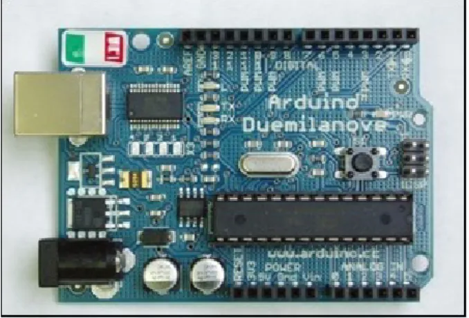
The Arduino Duemilanove ("2009") is a microcontroller board based on the ATmega168 (datasheet) or ATmega328(datasheet)(Shown in figure(6)). It has 14 digital input/output pins (of which 6 can be used as PWM outputs), 6 analog inputs, a 16 MHz crystal oscillator, a USB connection, a power jack, an ICSP header, and a reset button. It contains everything needed to support the microcontroller; simply connect it to a
computer with a USB cable or power it with a AC-to-DC adapter or battery to get started."Duemilanove" means 2009 in Italian and is named after the year of its release.
Fig. 6: Arduino Board
Working: The ‘Arduino’ board has components namely, ADC, microcontroller and other signal conditioning peripherals mounted on it. The input from the IR sensor is fed to the signal conditioning circuit and is converted to digital form by the ADC. The ADC output is then provided to the mounted microcontroller whose output is the required data (height in this case). The microcontroller gives results as it has been programmed to give expected output.
LCD Display :
To make the system user friendly a set of instructions are displayed on the LCD. Also the results are to be displayed after every measurement. For this purpose we use a 16*2 LCD.
It is a basic 16 character by 2 line display. Black text on Green background. Utilizes the extremely common HD44780 parallel interface chipset .11 general I/O pins are required to interface. Includes LED backlight. Working:The microcontroller output is forwarded to the LCD. Interfacing of the microcontroller with 16X2 LCD is carried out. The LCD displays the measured quantity.
IV. MICROCONTROLLER INTERFACE TO ANALOG SENSOR:
The interfacing between the microcontroller and the analog sensor used is as shown in figure(7).
Fig. 7: Microcontroller interfacing with analog sensor ATMEGA8 µC has an inbuilt 6 channel ADC. The analog sensors are connected through analog port (port C) of the µC. the analog sensors can be connected to the PORT A of the µC. The pin is ADC0(PC0). So the µC digitizes the analog i/p’s and the o/p is available in one of the PIC internal ADC registers. The user can now use this value to display on LCD or transmit to PC.
V. LCD SECTION
The interfacing between the Arduino board and the LCD is as shown in figure below.
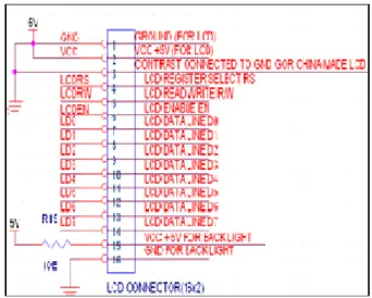
Fig. 8: Microcontroller interfacing with LCD LCD has 2 power sources, 1st VCC and GND are at 1
and 2 NO. Pins of LCD. Used to drive the LCD 3ma current consumption.2nd VCC and GND are at 15 and
16 NO. Pins of LCD are used to drive the backlight of LCD. 100 ma current.Total current consumption = 3ma + 100ma = 103 ma.So, in order to reduce the current requirement we are connecting a5 ohm resistance in series with the backlight pin VCC. This reduces the current consumption (100ma / 10ohm = 10 ma).Therefore new total current consumption = 10ma+3 ma =13 ma.
Fig. 9:LCD Connector.
LCD has 8 / 4 data lines and 3 control lines. The 8 data lines of LCD (pin 7 to pin 14 of LCD) are connected to the port D of µC ATMEGA8.
The control lines are LCD RS, LCD R/W, and LCD E. These 3 lines are connected to the port 2 of the ATMEGA µC. The LCD RS is for selecting the data or the code register. The LCDR/W is for choosing between reading and writing on LCD. LCDE is for enabling or disabling the LCD.
VI. SOFTWARE IMPLEMENTATION In order to carry out the height measurement technique and to appropriately calculate and display the same on the LCD, the microcontroller needs to be programmed accordingly with the inbult software of the Arduino board.The basic algorithm for software implementation is as shown below:
ALGORITHM
Step1: Start
Step2: Initialize ports Step3: Initialize ADC Step4: Initialize LCD Step5: Display project name
Step6: Enter into while loop(o/p =high) Step7: Read ADC
Step8: Compute height using multiplication factor Step9: Display the height
Step11: End
The microcontroller is programmed to compute height of the object under consideration. The ports, analog to digital convertor and the LCD is first initialized. While the IR sensor output is still available, the microcontroller continues to function. It takes the ADC input and computes height using a calculated multiplication factor. The final height measured is then displayed on the LCD. The algorithm is simple and straightforward as is the flowchart. An overall view of the project functioning is thereby available while studying the algorithm and flowchart.
VII. RESULTSANDDISCUSSION Thus by properly interfacing the sensor to the Arduino board, and after the required signal conditioning was done, the proposed model could then carry out measurement of height successfully.
We compiled the results over various instances and have successfully measured and displayed the heights of various objects. keeping an error margin of 2% the final output has been accurately measured otherwise. the obstacle detection and signal processing stages being **---most crucial, have also been successfully carried out.The input signal received by the receiver in the IR sensor is conditioned. It is then used to pass values to the preprogrammed microcontroller that generates the required output. This is then displayed on the LCD.
EXPECTED RESULT OBSERVED RESULT
120 CMS 119.9 CMS
105 CMS 105.01 CMS
80 CMS 80.01 CMS
76 CMS 76 CMS
VIII. CONCLUSIONANDFUTURESCOPE
Various manual methods have been used till date to measure height. The typical method is to stand in front of a height measuring scale and manually checking the height. However, a number of errors may be introduced due to human errors. The human eye cannot accurately calculate and hence is not a very efficient method. IN terms of future scope, the aging of trees cannot be accurately done by this method. Hence the need for
automatic height measurement. The advantages are:Small and light packaging. This improves the versatility of the device. Instant display without added delay further adds to itsbenefits and the automatic measurement removes human intervention all together and improves efficiency. Future applications include industries where the level of liquid in a container needs to be measured,in factories where the height of (say) wooden blocks needs to be known in order to cut them precisely,in medical clinics where the height of human beings has to be recorded, in tunnels for proper height detection of huge vehicles, in developing contour maps where height of buildings, mountains etc needs to be known.
IX. ACKNOWLEDGMENT
Any accomplishment requires the efforts of many people and this work is no different. We find great pleasure in expressing our deep sense of gratitude towards all those who have made it possible for us to complete this project with success.
We would like to express our true and sincere gratitude to Ms. Amruta Kulkarni, our mentor, for her dynamic and valuable guidance and keen interest in our project work. This project has been a result of combined efforts of our guide and us. She has been a strong and reassuring support to us throughout this project.
We would also like to express appreciation and thanks to all our friends who assisted us with their valuable suggestions and inputs, and we are very grateful for their assistance. We would also like to thank everyone else who has knowingly or unknowingly guided us
.
X. REFERENCES
[1 ] G. Benet, J. Albaladejo, A. Rodas, P.J. Gil, An intelligentultrasonic sensor for ranging in an industrial distributed control system, in: Proceedings of the IFAC Symposium on Intelligent Components and Instruments for Control
[2 ]Applications, Malaga, Spain, May 1992, pp. 299–303.
[3] F. Blanes, G. Benet, J.E. Simó, P. Pérez, Enhancing the real-time response of an ultrasonic sensor for map building tasks, in: Proceedings of the IEEE International Symposium on Industrial Electronics, ISIE’99, Vol. III, Bled, Slovenia, July 1999, pp. 990–995.
[4] V. Colla, A.M. Sabatini, A composite proximity sensor for target location and color estimation, in: Proceedings of the IMEKO Sixth International Symposium on Measurement and Control in Robotics, Brussels, 1996, pp. 134–139.
[5] H.R. Everett, Sensors for Mobile Robots, AK Peters, Ltd., Wellesley, MA, 1995.
[6] A.M. Flynn, Combining sonar and infrared sensors for mobile robot navigation, International Journal of Robotics Research 6 (7) (1988) 5–14. [7] Glassner, S. Andrew, Principles of Digital Image Synthesis, Vol. II, Morgan-Kaufmann, San Mateo, CA,1995.
[8] L. Korba, S. Elgazzar, T. Welch, Active infrared sensors for mobile robots, IEEE
Transactions on Instrumentation and Measurement 2 (43) (1994) 283–287.
[9] P.M. Novotny, N.J. Ferrier, Using infrared sensors and the Phong illumination model to measure distances, in: Proceedings of the International Conference on Robotics and
[10] Automation, Vol. 2, Detroit, MI, April 1999, pp. 1644–1649.
[11] A.M. Sabatini, V. Genovese, E. Guglielmelli, A low-cost, composite sensor array combining ultrasonic and infrared (IROS), Vol. 3, Pittsburgh, PA, 1995, pp. 120–126.
[12] P.M. Vaz, R. Ferreira, V. Grossmann, M.I. Ribeiro, Docking of a mobile platform based on infrared sensors, in:Proceedings of the 1997 IEEE International Symposium on Industrial Electronics, Vol. 2, Guimaraes, Portugal, July 1997,PP.735-740.