University of Twente
Designing a fall detection system
for elderly
Author:
Justin Krooneman, s1585991
in association with
KPN CUBES
Supervisor:
Dr Ansgar Fehnker
Abstract
This research looks at the falls of elderly and how elderly can be helped with falling. Of all the elderly falls 20% of the elderly on the ground for longer than an hour. Half of these elderly die within six months of the fall, even when they did not suffer any physical injuries of the fall, the psychological effects can be so dangerous it leads to death. More than half of these falls occur outside of the elderly’s home, where in home fall-detection systems have no view. However, state-of-the-art wearables lack the connectivity of itself and require another device to be close.
Therefore, the purpose of this research is to develop a wearable device which is able to detect a fall of an elderly person and is always connected to a network. The fall can notified to a caregiver or family member who can take appropriate actions through the network it is connected to. With the prototype which was developed tests were carried out. From these tests it can be concluded that it is possible to develop a device which has all the requirements as mentioned before. However, it requires time and effort from the elderly as well
Acknowledgements
I would first like to thank my thesis supervisor Dr. Ansgar Fehnker of the University of Twente. The door to his office was always open whenever I had a question about my research or writing. He steered me in the right the direction whenever he thought I needed it.
I would also like to thank my supervisor Kjeld Beijer from KPN. Without his passionate input in the project and help with setting up connections with the right people I would not have been able to finish this.
I would also like to thank everyone who has helped me either through supporting or motivating me to finish this research whom I have not mentioned before here.
And finally, I must express my very profound gratitude to my parents for providing me with unfailing support and continuous encouragement throughout my years of study and through the process of research-ing and writresearch-ing this thesis. This accomplishment would not have been possible without them.
Contents
1 Introduction 6
2 Related Work 8
2.1 Smart homes for elderly . . . 8
2.2 Wearables for elderly . . . 10
3 The Creative Technology Design Process 12 3.1 Ideation . . . 13
3.2 Specification . . . 13
3.3 Realization . . . 13
3.4 Evaluation . . . 13
3.5 Report Outline . . . 13
4 Ideation 14 4.1 Stakeholder Analysis . . . 14
4.1.1 Users . . . 14
4.1.2 Developers . . . 14
4.1.3 Legislators . . . 14
4.1.4 Decision makers . . . 14
4.1.5 Elaboration on the table . . . 15
4.2 Interview with a health care worker . . . 15
4.3 Requirements . . . 15
4.4 Personas . . . 16
4.4.1 Persona 1 . . . 17
4.4.2 Persona 2 . . . 18
4.4.3 Persona 3 . . . 19
4.4.4 Connectivity . . . 20
4.5 Summarizing . . . 21
5 Specification 22 5.1 The prototype . . . 22
5.1.1 Final prototype goal . . . 22
5.2 Testing . . . 23
5.2.1 Component Tests . . . 23
5.2.2 Usability Test . . . 23
5.2.3 Acceptance Test . . . 25
5.2.4 Initial Planning . . . 25
6 Realization 27 6.1 First Prototype . . . 28
6.1.1 MPU-6050 . . . 29
6.2 Second Prototype . . . 29
6.3 Third Prototype . . . 29
6.4 Final prototype . . . 30
7 Testing 31 7.1 Component Testing . . . 31
7.2 Usability Test . . . 32
7.3 Acceptance Tests . . . 33
8 Evaluation 36
8.1 Reflection on the prototype . . . 36
8.2 Reflection on the Research . . . 36
8.3 Conclusion . . . 37
8.4 Discussion . . . 38
8.5 Recommendations . . . 38
Appendices 39
A Arduino code of the first prototype 39
B Arduino code of the second prototype 41
C Arduino code of the third prototype 44
List of Figures
1 Notification of the Wellness mobile app . . . 8
2 A usual PERS . . . 8
3 A Holly sensor . . . 9
4 The Giraff Robot . . . 9
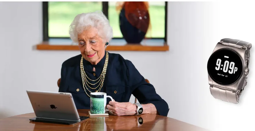
5 The Kanega Watch on an elderly . . . 10
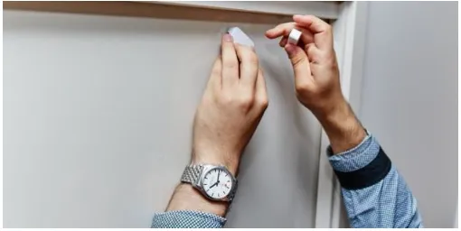
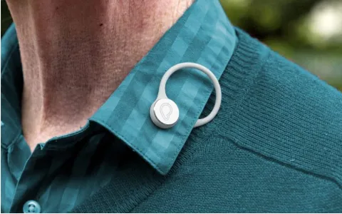
6 The Proximity Button on an elderly . . . 11
7 Creative Technology Design Process . . . 12
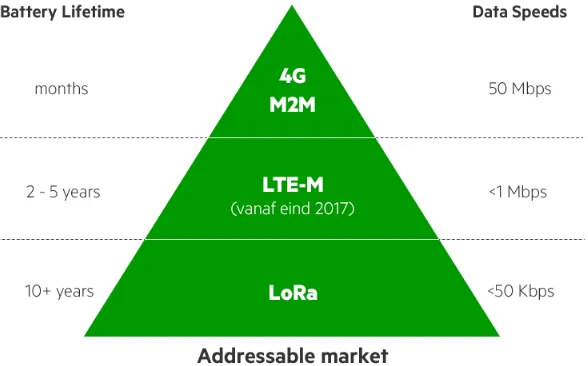
8 The differences between the different networks by KPN (in Dutch) . . . 20
9 How to use the different networks according to KPN . . . 21
10 Planning of the project . . . 26
11 Data flow in the prototype . . . 27
12 Setup of the prototype . . . 28
13 The MPU-6050 as used in the prototype . . . 29
14 Final Prototype as tested by elderly . . . 30
1
Introduction
Populations in the Netherlands are rapidly aging, with 3,1 million 65s in 2017 and 4,7 million over-65s expected in 2040 [1]. The result of this aging is that elderly homes are reaching their capacity [2, 3]. Municipalities therefore try to stimulate the elderly people to remain in their current home with the option of a supporting community nurse [4].
With the healthcare subsidies declining, the nurses and doctors are too busy to check on everyone continuously, thus leading to the invention of a button for the elderly which can be pressed in case of emergency or other type of solution [5, 6]. However, this button is not appreciated by a big part of the elderly community. They think the button is too big and ugly and prefer not to wear it, especially not if others are nearby. The device shows a certain lack of self-reliance and its missing an easy and accessible voice enabling i.e. based on LTE-M [6].
One of the main reasons why elderly should wear their emergency button is because a big part (56%) of the falls of elderly happen in public spaces[7]. More than 20% of the fallen elderly admitted that they were on the ground for more than an hour before help arrived or they were found. Half of the elderly who were on the ground for more than an hour die within six months, even when they did not suffer injuries from the fall [7].
Therefore, the goal of this project is to develop a device that is able to detect a fall of an elderly (or other user) and passively alarm a caregiver or family member. It should, however, elderly should not have to recharge this device more than once or twice a year. To reach this goal, certain questions will have to be answered. These questions are:
Question 1 Where do elderly fall most?
Question 2 What lack the current solutions?
Question 3 Do elderly feel safer while wearing the developed device?
Question 4 What should be changed in this device according to the elderly?
The first question will be answered by looking at already existing research and literature. To answer the second question a related work research will be carried out. Question three and question four require a working prototype to perform tests with.
How often do elderly fall and is it a major threat?
According to Kannus et al. 30% of the over-65 population living in a community and more than 50% that are living in residential care facilities or nursing homes fall every year. Half of the women who fell, fall more than once [8]. Kannus et al. also claim that over 80% of the injury-related admissions to hospitals of the over-65 population are due to falling. About 20% of the falls need medical attention, 5% result in a fracture, and other serious injuries as severe head injuries, joint distortions and dislocations, and in 5% of falls soft-tissue bruises, contusions, and lacerations arise.
Research by Bergland and Wyller recorded the number of falls of 307 elderly women, who are living in a community. This research has shown that 155 women fell one or more time, showing that instead of 30%, as stated by Kannus et al., more than 50% has fallen at least once [9, 8]. However, the group Bergland and Wyller tested was an over 75-years old group, while Kannus et al. speak of the over-65s population. Both Bergland and Wyller and Kannus et al. agree on the fact that age makes a difference on the number of falls, the older the person the higher the chance of a fall. The percentage of serious injuries and falls for elderly aged above 75 can be doubled to the percentages mentioned before. Kannus et al. and Bergland and Wyller both state that around half of the falls require medical attention.
falls, thus leading to further reduction of activities. This reduction may increase the dependency on family, increase the health costs for home care and the risk on more falls, which in turn leads to a downwards spiral. This view is supported by Pierleoni et al., however, they state another important observation in their research [7]. Namely, from the elderly who cannot get up from the ground for more than an hour, half of them pass away within six months after the accident, even if no direct injury from the fall has been sustained.
Where do elderly fall and how do they fall?
In the article of Kelsey et al. it is claimed that a major flaw in most published studies is that they combine all falls regardless of location [11]. Kelsey et al. claim that studies fail to separate indoor and outdoor falls, which can make it difficult to assess the magnitudes of associations between various falls. Moreover, associations may be completely missed when all falls are combined since indoor falls tend to occur to frail people who suffer from compromised health, but outdoor falls occur most often to active people.
In the research of Kelsey et al. it is discovered that only 53% of the 1122 measured falls do occur indoors and of the indoor falls only 77% occur in their own home. This means that of the 1122 measured falls almost half (47%) has occurred in an outdoor environment. Kelsey et al. discovered that the locations of outdoor falls were diverse but most commonly occurred on sidewalks (23%), yards or gardens (14%), streets or curbs (14%), outside stairs (13%), and parking lots (6%) [11].
An article by Pierleoni et al. supports this discovery and states that 31% of 3,628 falls are environment-related and 56% of the falls occur in public areas [7]. They also report that the falls are mainly due to pavement cracks and misalignments, steps, uneven ground and slippery surfaces. Also Li et al. agree with this and state that 512 participants reported at least one fall during the previous year [12]. More than half (58%) of the 512 participants reported an outdoor fall being their most recent fall. Middle-aged men 72% reported an outdoor fall as their most recent fall and for older men 57% stated an outdoor fall as their most recent fall. Women report a lower percentage of falls occurring outdoor, for middle-aged women 58% and for older women this was 51% [12]. They also show that the outdoor fallers report a longer time of having physical activity per month and thus being physically active could increases your chance of falling. However, the number of physical difficulties of outdoor fallers differ a lot with indoor fallers, with indoor fallers having significantly more physical difficulties [12].
Objective
Falling is a major threat for elderly, as big as 80% of the injury-related admissions to hospitals is due to falling and around half of the falls require medical attention. A major threat after a fall where the elderly has been unable to get up for more than an hour, is psychological injury. This even counts for falls without direct physical injury. This psychological injury could lead to a fear of falls which can lead to a downwards spiral which, in turn, could even lead to death.
Research has shown that being unable to get up after a fall is a real issue for elderly, it is important to design and develop a device which is able to autonomously alarm elderly carers when necessary. However, this research has also shown that most falls do not occur inside of the elderly’s home, but outside or in other public places. This means that outside fall detection should be an important aspect of the device that will be designed as well.
2
Related Work
In this section an overview of the current state-of-the-art will be given in the area of wearables designed for elderly as well as smart home designs for elderly. It will also be mentioned what the current products still lack regarding the information given in Section 1. Some of the many smart home products that will be further explored in Section 2.1 are the Wellness system, the Holly project and Giraff. In Section 2.2 there will be looked at wearables like the UnaliWear Kanega Watch and the Proximity Button.
2.1
Smart homes for elderly
Alarm.Com Wellness System
The Wellness system uses a network of sensors and actuators that are installed in the home of an elderly [13]. The system aims at family members and caregivers of elderly people, the system gives them the possibility to monitor the elderly’s activities and patterns. Also the system uses a mobile application which can alert the people that have been set as caregiver.
[image:10.612.227.380.321.481.2]It could for example alert the caregiver of the front door opening, which would look like the notification in Figure 1[14]. However, in case of emergency the Wellness system can be paired with an automatic Personal Emergency Response System (PERS) and instead of having to press the button of the PERS, as in Figure 2 , Wellness will automatically send the alert[15]. As an extra, Wellness is also coupled with the home security system of Alarm.com which enables the emergency services persistent awareness of what is happening.
Figure 1: Notification of the Wellness mobile app
[image:10.612.223.387.526.650.2]Holly Smart Home Project
Samsung and Deakin University have installed a “technology ecosystem” in five homes which will help address challenges associated with in-home aged care. The Holly project will be able to monitor aged care homes and can alert health care providers when strange activity is detected in or around the home [16].
[image:11.612.177.432.192.320.2]The AI program Holly is able to detect patterns in your behavior based on the sensor data it receives. The battery-powered sensors, see Figure 3, will be placed at various places in homes such as under the bed, in cupboards, on doors and in fridges[17]. Holly can track if your medicine cupboard has been accessed and because the sensors can also be picked up it can notice if you have been, for example, too long in the bathroom and will send the appropriate alert.
Figure 3: A Holly sensor
GiraffPlus
GiraffPlus is developing a network of sensors in the home of an elderly to make it possible to continuously monitor their health [18][19]. The sensors can register movement and detect if someone is lying still for an unusually long period, but the sensors can also measure blood pressure and body temperature. The system is able to quickly notify the patient’s caregivers, but the system can also be used for long-term health assessment. The system is analyzed by an intelligent system and is therefore able to chart an elderly’s sleeping pattern.
The heart of the system is a remote controlled robot which is equipped with a display and speaker (see Figure 4), known as Giraff. Elderly users will be able to choose who are able to control the robot and are able to see the data of the sensors. The researchers behind Giraff say that they aim to be a complement to the traditional methods as not all elderly prefer a visit to the health center or the hospital.
[image:11.612.171.441.502.655.2]In this section three different solutions for elderly smart-home alarm systems have been explored. All systems make use of different sensors, artificial intelligence and pattern recognition. However, there are some differences between the systems. The Wellness system is mainly aimed at person who cares for the elderly and that the carer is able to keep an eye on their loved-one(s), while the Holly system and Giraff are aimed at improving the quality of life for the elderly and making the elderly live at their own homes longer. However, all before mentioned systems lack one important functionality. Since Section 1 has shown that more than 50% of falls occur in other places than at home, functioning outside of home is a quite important functionality to have. It is almost impossible for a smart-home to embed this functionality because of a home’s static nature, therefore the next section will look at some systems that can be worn by the elderly.
2.2
Wearables for elderly
UnaliWear Kanega watch
The Kanega watch is an all-in-one, voice-controlled device designed to keep elderly independent, active and safe (see Figure 5) [20][21]. The Kanega watch is able to get you assistance at home or, since it is not connected to a home-based system or smartphone, on the go.
[image:12.612.72.517.344.573.2]The user can give it commands by voice and give it a name he can call, using his voice the user can set-up emergency assistance. By doing this the device will automatically connect to an operator who will dispatch medical emergencies or the user’s emergency contacts, depending on what has been chosen by the user. Additionally, the watch is able to remind you of taking your medicines and which medicines at different times. Kanega also ”understands” where you are and thus is able to guide you home if you are lost or in case of an emergency send help to your location.
Proximity Button
[image:13.612.184.424.157.307.2]The Proximity button is a simple Bluetooth device that connects to the carer’s smartphone [22][23]. It has only one major functionality, which is tracking if the wearer is still in the designated proximity of the carer. The device simply connects to the smartphone using Bluetooth and triggers an alarm on the if the wearer leaves the ”geo-fence”. Due to the few functionalities the Proximity Button has a battery-life of approximately six months.
3
The Creative Technology Design Process
The design process of Creative Technology1has been explained by Mader and Eggink in their bookA Design
[image:14.612.141.468.166.634.2]Process for Creative Technology[24]. This design process consists of four phases: Ideation, Specification, Realisation and Evaluation. In the remaining of the report these four phases will be used as guidelines. These four phases are shown and described in figure 7.
Figure 7: Creative Technology Design Process
3.1
Ideation
In the remaining of this section the four phases will be explained more in depth. In the Ideation phase it is specific for Creative Technology that a technology can be a starting point or motivation. This starting point is called tinkering, it has the goal to identify new applications with existing or new technologies. The main goal of the Ideation phase is to find relevant information and generate new ideas. This is can be achieved by setting up the requirements or personas, however inspiration for this can come from a flash or from an extensive brainstorm session. The result of the ideation phase is a elaborate project idea, together with the problem requirements.
3.2
Specification
In the specification phase it is discovered through functional specifications, user scenarios and early proto-types what the final prototype should look like and what it should be able to do. The result of this is a road-map to get to the final prototype using agile project management2 i.e., short iterations with multiple
prototypes over a course of 8 weeks. What is also added in this report, however, is the plan for testing the different prototypes in the realisation and evaluation phase.
3.3
Realization
With the prototypes specifications being clear from the specification phase. In this project the final project will be reached by following a linear model, this way backtracking in case of “wrong” decisions. The goal of this phase is to have a working prototype which can be tested in functional and user tests. However, the user tests will not be done in this phase yet, while the functional tests will be done every time a prototype is done.
3.4
Evaluation
The Evaluation addresses a number of aspects. Functional testing will be mostly done in the realisation phase so the only tests that will still need addressing are the user tests. Apart from these tests, reflection will also be a component in the evaluation. And possibly the most important part of the evaluation is to verify whether he decisions taken satisfy the user and client requirements.
3.5
Report Outline
As mentioned before in this section, the remaining of this report will follow the four phases. Section 4 will be the ideation phase in which the stakeholders, requirements and state-of-the-art is explored. Section 5 will contain the method of how the prototype will be made and the testing will be done. In Section 6 & Section 7 the realization of the prototypes and tests is elaborated respectively.
4
Ideation
In this section the requirements and possible ideas for the product will be explored and already existing implementations of this kind of product will be treated.
4.1
Stakeholder Analysis
A stakeholder analysis is done to better understand who the stakeholders are and how much their interests should be taken into account when making a decision. The Cambridge dictionary3 describes a stakeholder as follows:
“A person such as an employee, customer, or citizen who is involved with an organization, society, etc. and therefore has responsibilities towards it and an interest in its success”
In addition Sharp et al. identify four roles the stakeholders can have: user, developer, legislator or decision maker [25]. These four will be further explained in this section and the stakeholders for this project can be found in Table 1.
4.1.1 Users
Users are the people that use the product and interact with it directly. The final product will have one main target group of users, elderly. However, also professional caregivers and family members will be directly using the system. The influence of elderly is high, because they are the users that are mainly using the product. If they are not satisfied with the result they will not use it.The influence of caregivers and family members is low, since the only interaction with the system they have is in case of an emergency of an elderly.
4.1.2 Developers
The developers are the people that are involved in the development of the prototype. In this project KPN is a developer, since they offer a lot of support for the researcher, i.e. the writer of this report. The influence of KPN as a developer is medium. However, the influence of the researcher is high, since the product depends for a significant portion on his skills.
4.1.3 Legislators
Authorities that have connections with the law or politics, that may legislate guidelines or laws for the system are legislators. The municipalities are therefore the legislators in this project. They stimulate elderly to live at home longer and determine the subsidies elderly receive. Their influence in the project, however, is low.
4.1.4 Decision makers
Decision makers are the stakeholders who posses the power to “make or break” the product. In this project the main decision maker is KPN. KPN is the one who issued the project and is able to optimize and manufacture the prototype or not. Their influence in the project as decision maker is therefore high. Another decision maker is the supervisor from Creative Technology. His influence is mainly on the documentation and process of the project and therefore his influence is only medium.
Stakeholder Role Influence level
Elderly User High
Researcher Developer High
KPN - Business Development Decision Maker High
KPN - Product Development Developer Medium
Creative Technology Supervisor Decision Maker Medium
Caregivers & Family User Low
[image:17.612.148.466.71.173.2]Municipalities Legislator Low
Table 1: Stakeholders, role and influence level
4.1.5 Elaboration on the table
The table has been sorted by influence level of the stakeholder, and not on occurrence in the text. KPN is mentioned twice in the text and table, therefore both mentions in the table have gotten an extension in the table. On one hand there is the business development. These are the decision makers, they have the power to manufacture the prototype or not. And on the other hand there is product development. These are the developers which provide support where they can with regard to the researcher.
4.2
Interview with a health care worker
To verify the problem as stated before, the current situation in the field had to be discovered. Therefore, an interview with an anonymous female health care worker has been done. The interviewee has been working in the health care sector for four years now and is currently working for a nursing home. Therefore, she is also a stakeholder for the project, namely a caregiver. She confirms that due to the current cuts in the health care sector in combination with the stricter regulations have lead to elderly living at home longer than before.
According to her, in the nursing home a fall happens once a week. Often the same person and the majority of the fallers are women. The locations where elderly fall are mainly places where are only few objects, such as railings or handles, to support them. It does not happen often that an elderly has serious injury due to a fall, however it does happen regularly that an elderly has bruises or a black eye.
When elderly get admitted to the hospital it can take up to 3 weeks before they get home again. And in addition, the revalidation ranges, e.g., from six months up to the rest of their lives. Once they return to their homes they are more careful then they were, but in an unhealthy manner. If their walker is out of reach they already are scared of walking to get it.
This interview has shown that falling is indeed a big problem for elderly. Having fallen once increases their care in an unhealthy way, which also increases their risk of falling again. Also the places where they fall are mostly places where there are only few point of support for them. Since these elderly mostly live inside with constant care it is unknown if outdoor would increase the risk of falling. However, outside are less supports for the elderly than inside, which could increase the chance of falling.
4.3
Requirements
To deliver a research and possibly a product for the client, KPN, a brainstorm session has been held with “Product Owners” of KPN to find out the requirements for a possible product. The “Product Owners” main tasks are to find and analyze possible opportunities for KPN to step in. Therefore, as stakeholders they are the business developers. For example, they have done research into fall detection devices for elderly.
• The product must make it safe for elderly to remain living at home, but with enough autonomy. • The product must implement a passive alert instead of a button that has to be pressed by elderly. • The product must implement fall detection or prevention.
• The product must show that an alarm has been triggered.
The should requirements are not required for the product to work as it should. They are not essential, however without these functionalities the product is not ready to be tested. Theshoulds are as follows:
• The product should be protected by a casing.
• The battery should be able to live for a couple of months before needed to recharge.
Thecould requirements of the product are a nice extra to have, but are not required for testing. Without these functionalities the product does not miss any important functionalities. The could requirements are the following:
• The product could make use of the networks KPN offer, like LoRa and LTE-M. • The product could implement a dialog compatibility with an appointed person
• The product could integrate voice-assistants like Google Assistant and Amazon Alexa.
Thewon’t requirements will not be in this prototype due to the lack of time or other issues. Currently this product does not have anywon’ts
4.4
Personas
To give a clear view of the target group and their problems, personas of persons that would be in the target group are created. The following personas will be further described in this section:
4.4.1 Persona 1
General Paul de Vries
Age: 69
Social Status: Medium
Economic Status: High
Family: Wife and two sons (who live on their own)
Stakeholder: Elderly
Professional Background
Education: Masters in Psychology
Job: Retired psychologist
Personality
Known for: Empathic and smart solutions
Likes: Listening to classical music and football
Other traits: Has always traveled a lot through the Netherlands to find the most beautiful places the country has to offer.
4.4.2 Persona 2
General Henrieta Janse
Age: 88
Social Status: Low
Economic Status: Low
Family: Widow
Stakeholder: Elderly
Professional Background
Education: None
Job: Former-housewife
Personality
Known for: Shy and a bit of a loner
Likes: Playing board games and reading
Other traits: Undemanding
4.4.3 Persona 3
General Iris de Koning
Age: 38
Social Status: High
Economic Status: Medium
Family: Divorced with two daughters
Stakeholder: Caregivers & family
Professional Background
Education: Higher professional education in Human resource management
Job: Human Resource Consultant
Personality
Known for: Working hard and having many friends Likes: “Girls nights” and days off with her daughters Other traits:
Figure 8: The differences between the different networks by KPN (in Dutch)
4.4.4 Connectivity
In Section 2 it has been explored that all current solutions lack connectivity. They lack either connectivity in-house or outside. KPN has three different networks for Internet-Of-Things devices, the LoRa, LTE-M and M2M network. These will be further explained in this section.
LoRa
KPN’s LoRaWAN (Long Range Wide Area Network) or in short LoRa is a telecommunication network that is being used for long-range communication with lower power and is used in the internet of things [27]. The architecture exists of gateways, network servers and application servers. The nodes send an encrypted message through radio frequency (868 MHz in Europe) which is received by the gateway. This gateway is connected to the internet through network servers and the messages can be retrieved by an application server. The application server subsequently decides what happens with the data.
The LoRa network of KPN almost covers the Netherlands completely at the moment of this report, however, the connectivity of the LoRa gateways are limited as soon as they are positioned inside a house.
LTE-M
This specific category of theLong-Term Evolution network (Category M1) is one of the technical standards for Internet of Things (IoT) applications [28]. LTE-M IoT devices are connected directly to the 4G network, without the use of a gateway. The devices work on batteries what enables real-time data transmission, which can be used for location tracking for example.
At the time of writing only the area of Rotterdam and The Hague has been enabled LTE-M coverage, however, KPN is rapidly extending this to other big cities. Also, since they have only started with imple-menting LTE-M this year it does not have most functionalities (for example voice over LTE-M does not fully function yet).
M2M
Machine-to-machine communication, or telemetry, connects machines or devices at a distance and exchanges important information between those [29]. This increases the efficiency and decreases the costs of a business. M2M-communication uses a sensor which is attached to monitor a machine or other value. The smart-sensors are able to measure for example temperature, location, heartbeat, stress, light, movement, altitude and velocity. These sensors are connected to a SIM or landline which sends this data to a central server, which, in turn, interprets the data and activate the concerned actuators.
The most important differences between the KPN-networks In Section 4.4.4 three of the most prominent networks KPN supports have been explored and have been clarified. KPN already has made a clear overview of the major differences between the networks, which can be seen in figure 8[30][31].
[image:23.612.158.452.193.376.2]A big plus for LoRa is that it is the only network which does not require a SIM to be connected to the internet. However, LoRa has a slow reaction time in combination with a very low bandwidth. Perpendicular on that is the 4G(/M2M) network with its fast reaction times and high bandwidth, but according to Figure 8 these require a constant connection to the power grid, which disables any possibility of a wearable. In the middle of LoRa and M2M is the LTE-M network, it has a quick reaction time and is able to send up to 20 times more bits per second than the LoRa network.
Figure 9: How to use the different networks according to KPN
Considering that the maximum size of an SMS message is 140 bytes (0.14 KB), LoRa should have enough capacity to send the messages from the device to the internet. However, any extra sensor data or extensions are difficult to implement due to the lack of bandwidth and lack of connectivity. Also, LoRa is not connected to the network often, it could occur that a LoRa device is not connected for more than 30 minutes. For an elderly who is dependent on this device it is of utmost importance that he can trust the device, therefore the best option seems to be the LTE-M network.
4.5
Summarizing
In the previous section some scenarios for the use of a fall detection system have been explored and a couple of the already existing solutions of fall detection for elderly in smart-homes and wearables have been further elaborated. There are already a lot of complete solutions for smart-homes that are aimed at elderly which also support fall detection and geo-fencing.
5
Specification
This section will elaborate more on the design of the prototype, how testing the device will be done and what will be questioned in the evaluation. The general idea has already been explained in Section 4 and will be shortly repeated here. The device that will be designed and developed will be a wearable that detects a fall of an elderly and sends an alarm to the concerned people using one of KPN’s networks.
In Section 4 the requirements by KPN have been stated. Themusts will be already implemented in the early version(s) of the prototype, these are that the prototype needs to implement fall detection (or preven-tion) and has to implement a passive alert instead of the known button. If the prototype has implemented these two requirements it means that the product’s basic functionalities are working properly. However, this does not indicate the product is finished. The versions of the prototype after the musts are done will feature the shoulds of the requirements. It is also important that the prototype is able to notify the user that an alarm has been triggered, however it is not required for the product to function properly. Using the notification the user will know someone is being alerted to help them in case of an emergency. Also, the battery that is used to make the prototype mobile should be able to have a long lifetime, preferably of months so elderly don’t have to remember to charge it every day. In addition, the complete prototype should be protected by a casing which will, for now, be laser cut. The prototype will be tried to make as small as possible, not bigger than an Arduino and breadboard next to each other, to make the use as friendly as possible.
In the last and final version of the prototype the coulds will be implemented. The firstcould that will be implemented is the compatibility of LTE-M, this enables the last requirements. Setting up a voice call will be the next implementation in the prototype, this enables the users to speak with a person they want and ask for help. Finally as a last step to a commercial product the integration of voice-assistants could be implemented.
After each working prototype it will be tested by a small group of people who have a technological background to find possible problems and help with thinking how to solve these problems. When the prototype is ready to be tested with the target-group, the final prototype will be given to elderly to wear it for a day. After this day they will be asked questions about the functioning of the prototype, but also if they felt less afraid of falling.
5.1
The prototype
In Section 4 some possible implementations for a wearable have been seen already, a necklace, bracelet/watch and clip. These are already quite common for elderly and, thus, ideas for these designs have to be thought of.
The first prototype that will be developed will consist of an Arduino that is able to detect a fall and show it has detected a fall, for example with a sound or light. After this version the first extension will be a connection to the LTE-M network of KPN or LoRa if LTE-M is not ready yet. After the connection the next extension will be a voice that asks for verification of the alert and finally If all of these extensions works as they should the look of the design will be beautified and tried to decrease the size to make the final product as small as possible without losing functionality.
5.1.1 Final prototype goal
The final prototype will be a small device that can be worn on multiple parts of the body. This device measures acceleration and rotation using an accelerometer and a gyroscope, using this data a fall can be detected. In case of a fall that the device detected, it will start a ”Voice-over-LTE-M” connection with the person the user chose. This way the user knows someone is coming and if necessary the called person can inform the emergency services.
could be a fall. If the Arduino detects a fall, the data of the last 5-15 seconds is send to the database using the LTE-M network. This data is then processed to find any similar falls in the database. However, it could be that the Arduino detects a fall, while the person did not fall in reality. In this case the user could turn off the alarm by pressing a touch sensor on the device. This is also send to the database then so the next time the same data is send to the database it will not return a fall. However, it is also possible that the user did fall, but the Arduino did not detect it. In this case the user can press the touch sensor for 2-3 seconds to activate the alarm manually, this data is then also send to the database. This way also a form of machine learning is also incorporated in the design. The complete activity diagram can be found in Appendix D.
5.2
Testing
The testing will consist of different types of tests. During the iterating process of the prototype the different components will be individually programmed and tested before implementing them in the complete proto-type. The components will then be tested thoroughly to prevent the possibility of an emergency shutdown. When such a component has been installed in the complete prototype, it has to be tested as a whole to find problems and bugs. These tests will first be performed by the developer and after that with peers.
When the prototype has reached a point where it will be used as a working commercial product it is required to be tested with a bigger group of peers at first. This is required to find more technical problems and improvements, which elderly users/testers would have no knowledge. Therefore testing with peers is likely to require less time and is more effective.
5.2.1 Component Tests
During the development of the prototype new components will be implemented in the complete prototype. When a prototype version has one to three new functions or functionalities it is required to be tested as a whole, instead of each component separately in the system.
These tests are meant to find out if the different components work properly together without device-breaking bugs and repair if they do not. The components that require to be tested are the following4:
Test CT1 Touch sensor is controlling the LED.
Test CT2 MPU-6050 is sending understandable data.
Test CT3 If the MPU-6050 registers a fall the alarm should go on.
Test CT4 The user is able to turn of the alarm.
Test CT5 The casing is able to withstand the shock of a fall.
Test CT6 If a user does not turn off the alarm, it should setup a call.
When and with whom this testing will be done is determined by the developerad hoc. Since a component could only require a simple fall test, but it could also include a complete system. This means that it is hard to determine the location and testers at this time.
5.2.2 Usability Test
Once the prototype can be used commercially it has to be tested by usability tests. These tests are simple tasks for the tester, for example”jump twice”or ”walk to that couch and sit on it”.
The first usability tests will be carried out with experts, the experts will be peers who have some knowledge of the prototype instead of the target group. This decision has been made on the grounds that peers have some knowledge about the used technologies and enable for quicker, more effective and more precise troubleshooting and problem fixing. To achieve this the experts require knowledge in the field of
product development, therefore the peers will be students in the fields of computer science, design and/or electrical engineering. They will be asked to do simple, yet, specific tasks while wearing the prototype. Afterwards they will be asked if the product behaved intuitive, what technical problems occurred and design flaws they encountered. The exact scenarios, tasks and points the observer should look at are5:
Scenario 1 An eldery person just got home and wants to sit in their favorite chair. Because of their tiring day they stand in front of it and fall in it.
Test UT 1 Walk to that chair and stand in front of it with your back to the chair. Fall in the chair.
Points of interest The alarm/LED should not turn on, however, in case it does. Is the user easily able to turn it off ?
Scenario 2 An eldery person is walking the stairs upward, but missteps at the top therefore hitting it a lot harder than the rest.
Test UT 2 Walk the stairs normally.
Test UT 3 Walk the stairs, but when you reach the top act like you thought there was another step.
Points of interest The alarm/LED should not turn on when normally walking up the stairs, however, in the case of the misstep it could happen that the prototype registers a fall. In this case:
Is the user easily able to turn it off ?
Scenario 3 An eldery person is walking and suddenly falls hereby breaking the hip. Unable to call for help due to the inability to get up.
Note: to prevent real injury the test persons were asked to fall on a couch.
Test UT 4 Walk in front of this couch and fall on it, while lying down do not move.
Points of interest The alarm/LED should turn on with a fall. However, look closely if the test person’s fall looks real enough to register a fall. Also, do not turn of the alarm and check if the tester notices the change in behavior of the alarm.
After the testing the testers were asked if they would also like to participate in answering questions about the tested prototype. The questions asked help to find possible bugs and problems, therefore the questions help with improving the next prototype. The questions asked after the tests are the following:
Question 1 Do you think this prototype is a good way to find out if a person has fallen? If not, what could be improved or is an alternative?
Question 2 Did the prototype make any errors? How much and when?
Question 3 What do you think about the design of the prototype? What should be changed? (Size, material and so on)
Question 4 Were you able to turn off the alarm when you wanted to? Should anything be changed about this?
Question 5 Do you have any other remarks or suggestions?
5.2.3 Acceptance Test
If the usability tests are successful and the prototype is functioning as expected, the target group will be asked to perform some small tests. These final tests are to find out what the intended users think of the prototype and if all the functions of the prototype work for them as well without giving false alarms.
Since the prototype has already been tested with peers, the prototype should not have any bugs left in the system. This way the elderly can work with a complete functioning system and have a better understanding of what the prototype does. Before the tests the elderly will be explained what the purpose of the project is and how the prototype functions. They will be explained what the fall detector actually measures, acceleration, but also how the emergency button works. After the tests the elderly will be asked questions about the prototype, the tests and their opinion of the idea of the system. The exact tasks and questions are6:
Test AT 1 Walk to that chair and stand in front of it with your back to the chair. Fall in the chair.
Points of interest The alarm/LED should not turn on, however, in case it does. Is the user easily able to turn it off ?
Test AT 2 Walk the stairs normally.
Points of interest The alarm/LED should not turn on when normally walking up the stairs, however, it could happen that the prototype registers a fall. In this case: Is the user easily able to turn it off ?
Test AT 3 Turn the emergency alarm on
Points of interest Look closely if the user understand what is happening and if the user has difficulties performing the task.
After the testing the elderly were asked if they would like to participate in answering some questions about the tested prototype. The questions asked help to find possible problems and opinions, therefore the questions help with answering the research questions. The questions asked after the tests are the following:
Question 1 How many times do you fall? (once a week, once a year, etc.)
Question 2 Are you afraid of falling? / Do you keep in mind that you could fall?
Question 3 Do you still experience fear due to previous falls?
Question 4 Would you use the current prototype?
Question 5 What could be improved in the prototype?
5.2.4 Initial Planning
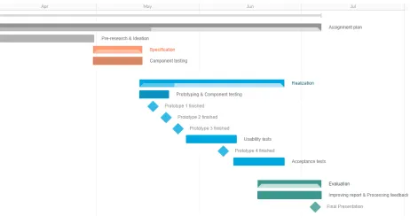
The initial planning for the project can be seen in Figure 10. The Pre-research & ideation phase were completed on the 30th of April, so this was the start of the specification phase. The specification phase has
taken up to two weeks, after which the realization phase and the tests start on the 7th of May.
This phase starts with early prototypes and Component Tests, which can take up to two weeks. After these two weeks a preliminary final version of the prototype has to be finished so the Usability Tests can start. These tests are designed to find and solve bugs in the system. Finding bugs by testing and solving the bugs is expected to take two weeks in total. This means the “final version” of the prototype is done after four weeks. The user Acceptance tests should not take longer than a couple of days of testing, so approximately one week.
[image:28.612.79.541.225.478.2]The last phase is the evaluation phase. This phase will commence around the 18th of June. However, prototyping does generally take longer than it is expected and therefore it is still acceptable to start one week later, on the 25th of June. The evaluation is expected to take up to 2 weeks, this includes processing feedback received from the supervisor and critical observer. The final presentation will be held on the 5th of July and the project is expected to be done by then when following this planning.
6
Realization
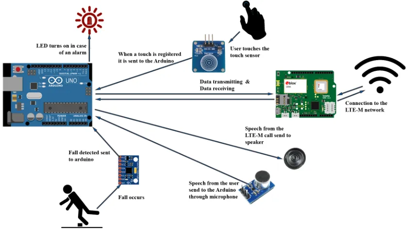
[image:29.612.100.521.252.491.2]The road map for the realization of the prototype has already been explained in Section 5, therefore this section will describe the prototype’s development process. The prototype will need to consist of multiple components with each having its own function. The MPU-6050 (see Section 6.1.1) is the accelerometer and gyroscope that is used in the prototype and therefore one of the first components in the complete prototype. An LED is used as alarm in the first prototypes, but could be replaced with a speaker. In the early prototypes the alarm will be turned off by a simple button, while a later stage will feature a capacitive touch sensor to turn the alarm on and off. However, the most important component is the Arduino Uno which processes all the data from the other parts. In addition the prototype also gets a connection to the LTE-M network of KPN, this will be done using the same component KPN uses, the Sodaq SARA AFF R410M. Finally, to use the LTE-M network to have an emergency call an amplifier, speaker and microphone will be incorporated in the final design. The complete data flow can be seen in Figure 11.
Figure 11: Data flow in the prototype
Figure 11 shows the ”movement” of the data. The first prototypes will mainly focus on the basic components. These components are the MPU-6050, the LED and the touch sensor (respectively bottom left, top left and top center in Figure 11). All data goes to or comes from the Arduino (center left in Figure 11) and will be processed in there. The MPU-6050 registers acceleration and orientation of the user, this information is then send to the Arduino which acts accordingly. If there has been a fall the Arduino sets the LED’s state to on and starts listening to the data send by the touch sensor.
6.1
First Prototype
The first prototype consists of an Arduino Uno with a touch sensor, accelerometer and gyroscope connected to it. Using these sensors the basic functions of the prototype can be tested and see if it works intuitively. This prototype will not yet have the aesthetics of the final prototype, therefore the main function of this prototype is to discover possible bugs, other problems and provide a foundation to build on. The accelerometer that is used is the MPU-6050 on a GY-521 breakout board (see Section 6.1.1). The code which was uploaded to the Arduino can be found in Appendix A.
This early version of the prototype showed an extensive problem on the I2C-bus of the used Arduino, which only came to light after some elaborate debugging. By an unsafe shut down the I2C-bus was stuck and even comprehensive recovery programs were not able to restore the I2C-bus of the Arduino. At last, it could be concluded that this Arduino was unusable and the first tests with the new Arduino immediately were successful. The raw values of the accelerometer were unusable and had to be mapped to values that were easier to interpret.
The hardware components on the first setup are the MPU-6050, a capacitive touch sensor and a RED LED, the connections can be seen in Figure 12. For each of the components a code was written so if everything worked it could all be implemented at once. The MPU-6050’s code consisted of measuring values and printing them on the screen. While the code of the LED and touch sensor was made together immediately since it only includes touching the sensor to activate the LED.
[image:30.612.166.417.364.626.2]Combining all codes and components into one device has led to the code of Appendix A. Except on a number of minor bugs the merge of the codes went flawless and was realized quickly. The MPU-6050 is used to determine if there has been a fall or not by the user and in the case of a fall the LED is turned on. However, the LED can be turned off by the user, in case of a false positive, by touching the touch sensor.
6.1.1 MPU-6050
The InvenSense MPU-6050, see Figure 13, contains two sensors in a single chip, it has a MEMS accelerom-eter which measures acceleration and in addition it features a MEMS gyroscope which is able to measure orientation of the chip[32]. The MPU-6050 contains 16-bit analog to digital conversion hardware for each channel, what makes it very accurate in comparison to other accelerometers. For example the Bosch Sen-sortec BMA250E has only 10-bit conversion. Also, the MPU-6050 is able to capture thex,y andz channel at the same time. To interface with the Arduino the sensor uses the I2C-bus.
[image:31.612.212.399.235.377.2]The sensor also has a Digital Motion Processor (DMP) which can be programmed with firmware and is able to do complex calculations with the sensor values directly on the chip. This reduces the load on the Arduino and is even able to process other sensors’ values. However, the use of the firmware is very obscure to use and will therefore be not be used in the early prototypes. If in a later stadium there is time left it could be considered to implement.
Figure 13: The MPU-6050 as used in the prototype
6.2
Second Prototype
To increase the functionalities of the device a second and improved version of the first prototype is made. The upgrade is only made in the software and software design, so this version is still using the setup as shown in Figure 12, however the new code can be found in Appendix B. One of the functions that was not yet implemented was that the user could not activate an alarm in case of an emergency or when the device did not register a fall. However, this improvement required a complete rewrite of thecheckButton function, since that was written for turning the LED off instead of multi-functional.
The second improvement is the removal of the delays that were plaguing the program, this has been solved by using themillis() function of Arduino (which can be seen in Appendix B, function: blinkOn()). The final improvement is the increased severity of a fall. If a fall has been registered and the LED is static on for more than five seconds, the LED goes to its blinking state, indicating it will soon setup the emergency call. This also means that if the user activates the alarm, it immediately goes to this state. This does not mean it is no longer possible to turn it off in case of an error, both alarms can be turned off.
6.3
Third Prototype
The calibration function had to be implemented since the accelerometer does not do this by itself properly. This function requires the user to stand still and will use this to determine the correct acceleration and orientation of the user. Also, to enhance the life of the batteries the Arduino has been upgraded with the use of a power-saving mode. The effect of this power-saving mode has not been tested yet, but it is said that it is extremely useful in combination with Li-ion batteries. The last improvement on the second prototype is the casing that has been laser cut. This prototype has been used in the Usability Tests.
6.4
Final prototype
In section 5.1.1 the goal of the final prototype has been explained and the most basic functions are summed up in section 5.2.1. The final prototype (Version four) does not have all the functions from the goal due to time constraints. However, all basic functionalities are working.
[image:32.612.113.498.309.588.2]The casing has been improved in comparison to the previous prototype. This casing is somewhat bigger due to the LTE-M component that was fitted in, but all components fit tighter together. The LTE-M shield does not work in this prototype yet, because of the time constraints. This means that the prototype does not have access to KPN’s M network and cannot send a message when the user has an accident. The LTE-M shield is fitted in the prototype, but the software and network chip are not working as desired yet. This version has a smaller delay after the button has been pressed, this has been changed from 1500 milliseconds to 1000 milliseconds. This prototype has been used in the Acceptance Tests.
7
Testing
7.1
Component Testing
To ensure a working product in the final tests there have been a lot of small intermediate tests of all components apart and also some tests to test the working of the then latest prototype. These tests have also been described in Section 5.2.1, this section will use the same reference to these tests: CT. Also, in this section it will be described which tests were carried out and what could be concluded from these tests.
The first tests that were done were to test the touch sensor together with the LED (CT1 in Section 5.2.1). If the touch sensor was touched the LED should turn on or start blinking. Here it already became clear that a small delay was needed in case the sensor was touched. Even though a delay should be avoided, since it stops the complete program for the specified time, it was not too dangerous in this case. Mainly because touching the sensor means that either the alarm should be turned off or on. If a user touches the sensor this it means he needs help or no help is needed. It is assumed that during the delay (of 1 second) the chance something happens to the user is nil. Also not using this delay will result in jumping of the sensor (registering on and off in a very short time).
The component that was installed in the prototype after the LED and touch sensor was the MPU-6050. This sensor contained the accelerometer and gyroscope that were used for the prototype and were therefore essential for the working of the prototype. The first test was done by simply trying to read the values of the MPU-6050, successfully. However, the values were unusable since they were the raw values.
Using the library of Jeff Rowberg7these values were normalized so they are interpretable and workable (CT2). However, after the first use of this library the I2C-bus of the Arduino was broken and a new Arduino was needed, as explained in Section 6.1.1. After solving this issue the MPU-6050 was tested together with the already working LED and touch sensor (CT3 & CT4). Separately all components were working and while programming the components it was taken into account that it should be compatible with the other components. This proved to be useful, because the tests to test if everything was giving correct values did not show any problems.
The first ”field test” was carried out with this prototype (CT5). The developer got the prototype taped with duct tape to his chest and walked to test if the threshold for detecting a fall was not too low. This did require some optimization, because the values were sometimes quite random. Therefore it became clear that the prototype required a calibration function at the start of the program. When the threshold was found at an optimum for the test the user was falling on a bed to test if it registers a fall. The accelerometer then showed it was indeed measuring a fall most of the times. However, because of the user being a bit cautious to not break the prototype when falling some falls were not registered.
The prototype that was now finished does not have the LTE-M function, due to time constraints this version has been used in the Usability Tests. Nevertheless, the prototype is still being improved to make it LTE-M compatible for the final Acceptance Tests.
7.2
Usability Test
In Section 5.2.2 it has been explained why the Usability Tests are performed with peers. The goal of these small tasks is to find bugs and other improvements for the prototype. Also, it has been mentioned what questions will be asked after the tests.
For the Usability tests there are five participants, ranging in age from 21 to 26. The participants all had some knowledge in electrical engineering and computer science. All of the testers were acquaintances to the supervisor. Because of privacy reasons the real persons names are not mentioned and they are called : “Tester 1”, “Tester 2”, “Tester 3”, “Tester 4” and “Tester 5”. To transform the prototype to a wearable, it was duct-taped to the chests of the testers during the tests.
Age UT1 - Sit on
chair
UT2 - Climb
stairs
UT3 - Stairs with misstep
UT4 - fall on couch
Remarks Remarks Remarks Remarks
Tester 1 22 a User cautious a - a - b & e
-Tester 2 21 c - a - a - b & f
-Tester 3 21 c - a - a - b & e
-Tester 4 26 d User panicked a - a - b & e
-Tester 5 23 a - a - a - b & f
-Table 2: Results Usability Tests
Clarification on table 2 :
a = Alarm not on b = Alarm on c = Easy to turn off d = Not easy to turn off e = Noticed difference of LED f = Did not notice difference of LED
The tests required each tester to execute four different tasks in total (UT1, UT2, UT3 and UT4), all five testers were able to complete the tasks successfully. The first task for the testers was to walk to a chair and fall in the chair. Tester 1 was cautious while falling in the chair and did not trigger an alarm. Tester 2 and Tester 3 both fell rough in the chair and triggered the alarm. Both Tester 2 and Tester 3 were able to easily turn off the alarm. Tester 4 triggered the alarm while falling in the chair, however turning off showed some difficulty. Tester 4 pressed the button for a second time setting the alarm back on. This caused Tester 4 to panic lightly and pressing the button twice again. The third time Tester 4 successfully turned the alarm off. Tester 5 fell in the chair without triggering the alarm.
[image:34.612.77.539.198.300.2]7.3
Acceptance Tests
The goal of the user tests is to find out what the intended users think of the prototype and if all the functions that are in the prototype work for them. In Section 5.2.3 the tests have already been explained, however these tests were designed assuming a complete working prototype. In Section 6.4 it has already been described that the prototype is not finished completely yet. Since it does not contain the LTE-M function, a message cannot be sent to the desired person. However, the tests did not require a working LTE-M functionality and therefore the explanation given to the elderly was still the same as intended. It was told to them that if they fell a message would be send to a specific person.
Originally there were 5 elderly asked to participate, however the test location was in a meeting place of a flat for elderly. This location was easily accessible and observable for all residents and after the first two tests more elderly came to see what was happening. The also told their opinions on the questions making the interview look like a group conversation in which the elderly present seem more confident. The elderly also supplemented each other on some questions.
The results of the Acceptance Tests can be found in Table 3 and will be further clarified here. Because of privacy reasons the real persons names are not mentioned and they are called : “Person 1”, “Person 2”, “Person 3”, “Person 4” and “Person 5”. Person 1 is an elderly who lives alone, person 2 and person 3 are elderly live together, person 4 and person 5 live alone but see each other on a daily basis. Person 1 was tested alone, Person 2 and Person 3 were together while tested. Person 4 and person 5 were also together, but also other residents who were curious what was happening. These “remaining residents” were not tested, because they did not have time for the tests. However, they did give input on the questions after the tests.
AT1 - Sit on chair
AT2 - Climb
stairs
Extra - descend stairs
AT3 - Set alarm on
Remarks Remarks Remarks Remarks
Person 1 a - a - - Not tested d Multiple
touches Person 2 a Elderly
cau-tious
a Very low pace b - d Kept finger
on sensor
Person 3 a - a - a - c
-Person 4 a Elderly cau-tious
a - b - c
-Person 5 a Elderly cau-tious
a - a Quite rough c
-Table 3: Results Acceptance Tests
Clarification on table 3 :
a = Alarm not on b = Alarm on c = Easy to turn on d = Not easy to turn on
The first task for the elderly was to “fall” in a chair. Only Person 1 and Person 3 did really “fall” in the chair, the others were quite careful even though they knew there was a chair behind them. None of the alarms was triggered in this test. For the second task the users were asked to walk the general stairs of the flat for one floor. At the top of the stairs it was observed if the alarm was on or not. In general the pace of the elderly walking the stairs was significantly lower compared to the peers in the Usability test. Specifically Person 2 had an extraordinary low pace, also compared to the other elderly. No alarms were triggered while climbing the stairs.
[image:35.612.98.516.330.480.2]This new task was not tested with Person 1 anymore, however it was tested during the remaining tests. Person 5 did come down the stairs quite rough, however no alarm was triggered. Person 3 and Person 4 came down the stairs comparable, but only Person 4 triggered the alarm.
7.3.1 Questionnaire
Person 1 How often do you fall?: Sometimes, this happens mainly due to inattention.
Are you afraid to fall?: No, I am confident in my abilities to remain on my feet.
Do you still notice consequences of previous falls?: No, but I pay extra atten-tion with everything.
Would you use this prototype?: No, I don’t need it.
What would you like to see improved?: Less time between alarm turning on and the message being send, 2 or 3 minutes is enough.
Person 2 How often do you fall?: Around once a month
Are you afraid to fall?: Yes, I keep it in mind with everything I do.
Do you still notice consequences of previous falls?: Yes, I am still afraid to fall due to a fall I made ten years ago.
Would you use this prototype?: I would like to use it, but it is not necessary because we live together.
What would you like to see improved?: It should be invisible to wear and show how a fall occurred, because mostly we don’t know why we fell.
Person 3 —
How often do you fall?: Now and then, but no serious injuries
Are you afraid to fall?: No.
Do you still notice consequences of previous falls?: No, but I pay extra atten-tion when I am home alone.
Would you use this prototype?: No, I don’t need it because we live together.
What would you like to see improved?: It should verify if a fall occurred, be able to turn the device off and it should be made a lot smaller.
Person 4 How often do you fall?: Once a year
Are you afraid to fall?: Not afraid, but I keep it in mind.
Do you still notice consequences of previous falls?: Only the days after the incident it is a bit painful.
Would you use this prototype?: It looks useful, but I don’t need it
What would you like to see improved?: Make the device smaller and choose who is being called.
Person 5 How often do you fall?: Once a year
Are you afraid to fall?: No.
Do you still notice consequences of previous falls?: No, not really.
Would you use this prototype?: No, I don’t need it because I don’t fall that often nor that badly.
8
Evaluation
This section elaborates on the progress of the prototype and the research that has been done. Also, this section will give an answer to the research questions and will conclude if the goal of the project is reached. Furthermore, other conclusions that were found during the project will be discussed. In the end the recom-mendation for future research will be given.
8.1
Reflection on the prototype
The original requirements from Section 4.3 were prioritized using the MoSCoW method. During the devel-opment of the prototype this prioritization was followed. The first embedded features, therefore, were also the most important requirements, themusts. These features and requirements covered the basic functions of the prototype. This meant, firstly, being able to detect a fall of an elderly. This detection should, secondly, give a passive alarm without having to press a button in case of an emergency. And thirdly, making it clear an alarm has been triggered. These requirements and functions have been embedded in the first prototype. This first prototype did require the most time to be finished. This was caused by the communication between the accelerometer and the Arduino. The accelerometer did not connect to the Arduino and it took six days to find out what the actual problem was. The I2C-bus of the Arduino was “hanging” in theexit-state and even I2C-bus recovery programs were not able to solve this problem. Using a new Arduino was the easiest option to fix this.
If the six days that were “lost” on finding the problem, could have been spent on the user tests it would have been possible to ask elderly to wear the device for a day and give their opinion about the autonomy. Since this was one of themust requirements it should have been tested as well. The requirements that were somewhat less important were theshould requirements. One of these was the casing for the prototype, this requirements has been met. However, in figure 14 it can be seen that this prototype’s casing is still very raw. This was also confirmed in the user tests, where one of the main problems for the elderly was that the prototype was so bulky.
In Section 6.4 it has been explained that the LTE-M compatibility was not implemented in the system. This meant that the most unique functionality of the fall-detection wearable, the LTE-M connection, was not working. Therefore, the final prototype was not as spectacular as desired in the beginning of the development. Looking back at the final prototype and the goal of the project, it could have been more feasible and unique to have the LTE-M component in it. In that case the Arduino and LTE-M shield could have been used to add more components, like a button and accelerometer, to the prototype. However, what has to be taken into account is that the LTE-M of KPN is not used in any commercial product at the time of writing. Also, the LTE-M network was still in development leaving only little space for support from KPN. Therefore, it could have been possible that the LTE-M compatibility was not finished in case this choice was made.
8.2
Reflection on the Research
In the Pre-Research, Ideation and Specification phase of the research regular contact and visits were main-tained with KPN. The meetings that were held with the Product Owners were not only helpful for deter-mining the requirements. Also, the first feedback on prototype ideas came from the Product Owners. In these feedback moments they gave a lot of positive criticism and a new angle of approach for how to make the product work.
The Usability Tests were performed with the unfinished prototype to get feedback about the fall-detection component. However, another, known, risk was the LTE-M component of the prototype. Because the Usabil-ity Tests showed that the fall-detection was working, the main focus could become the LTE-M component. After trying for a week to get the LTE-M component work, it was clear that help was required to get the LTE-M compatibility in the prototype. This help was initially looked at at the LTE-M team of KPN, since they had already helped with the first steps into setting up LTE-M in the prototype. The week in which was asked for their support, they had deadlines themselves which they had to meet. If an appointment with them was made one or two weeks before then, they could have tried to reschedule other things. Regrettably, this meant that it was not possible to finish the prototype in the given deadline.
Therefore, the Acceptance Tests were carried out without the LTE-M functionalities of the prototype. The impact of the lack of an LTE-M component only became clear during these tests, since the current prototype only exists of a “simple” fall detector. It had to be prevented that the elderly blamed any wrongs of the prototype on the lack of this component. So, a sort of wizard of Oz8 way was used to simulate the LTE-M component. By saying the LTE-M component was certainly in the prototype and if they would leave the alarm on for too long, a message was send to the researcher. However, this does not mean that the outcome of the tests can be disregarded. The elderly did believe a message was send after a fall using the LTE-M network.
8.3
Conclusion
It is possible to develop a device which is able to detect falls of elderly and passively alarm a caretaker or family member. It will, however, take time and effort on the part of the researchers and elderly to find a fitting solution and final product. The elderly who participated in the tests made very clear that the current prototype is not ready to be used. The current prototype is too big to be worn invisible and therefore the elderly would never use it now. Another argument some of them gave was that they “don’t need it”. Persuading the elderly into wearing the device will not be easy, but if the device does not hinder them in any way it is possible.
![Figure 1[14]. However, in case of emergency the Wellness system can be paired with an automatic PersonalIt could for example alert the caregiver of the front door opening, which would look like the notification inEmergency Response System (PERS) and instead](https://thumb-us.123doks.com/thumbv2/123dok_us/9692987.470627/10.612.227.380.321.481/emergency-wellness-automatic-personalit-caregiver-notication-inemergency-response.webp)